Huge milestone.. My entire X axis is assembled! (I’ve held rods alongside pieces many times when showing this to friends, trying to describe how in will work, and now I can just show you.
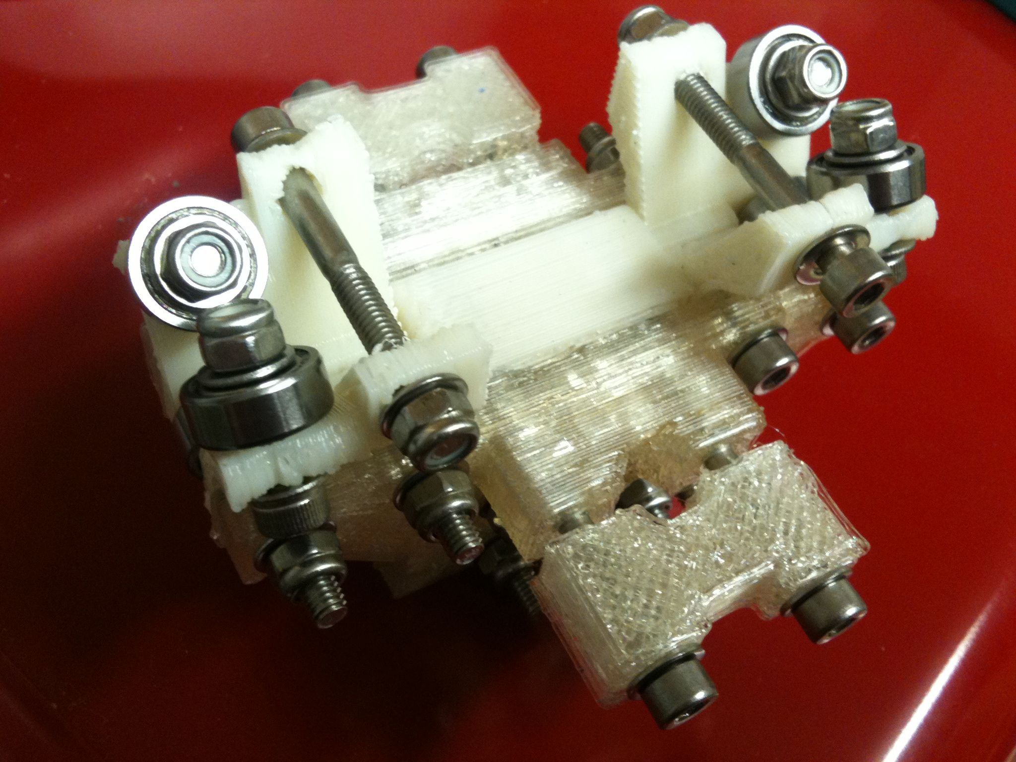
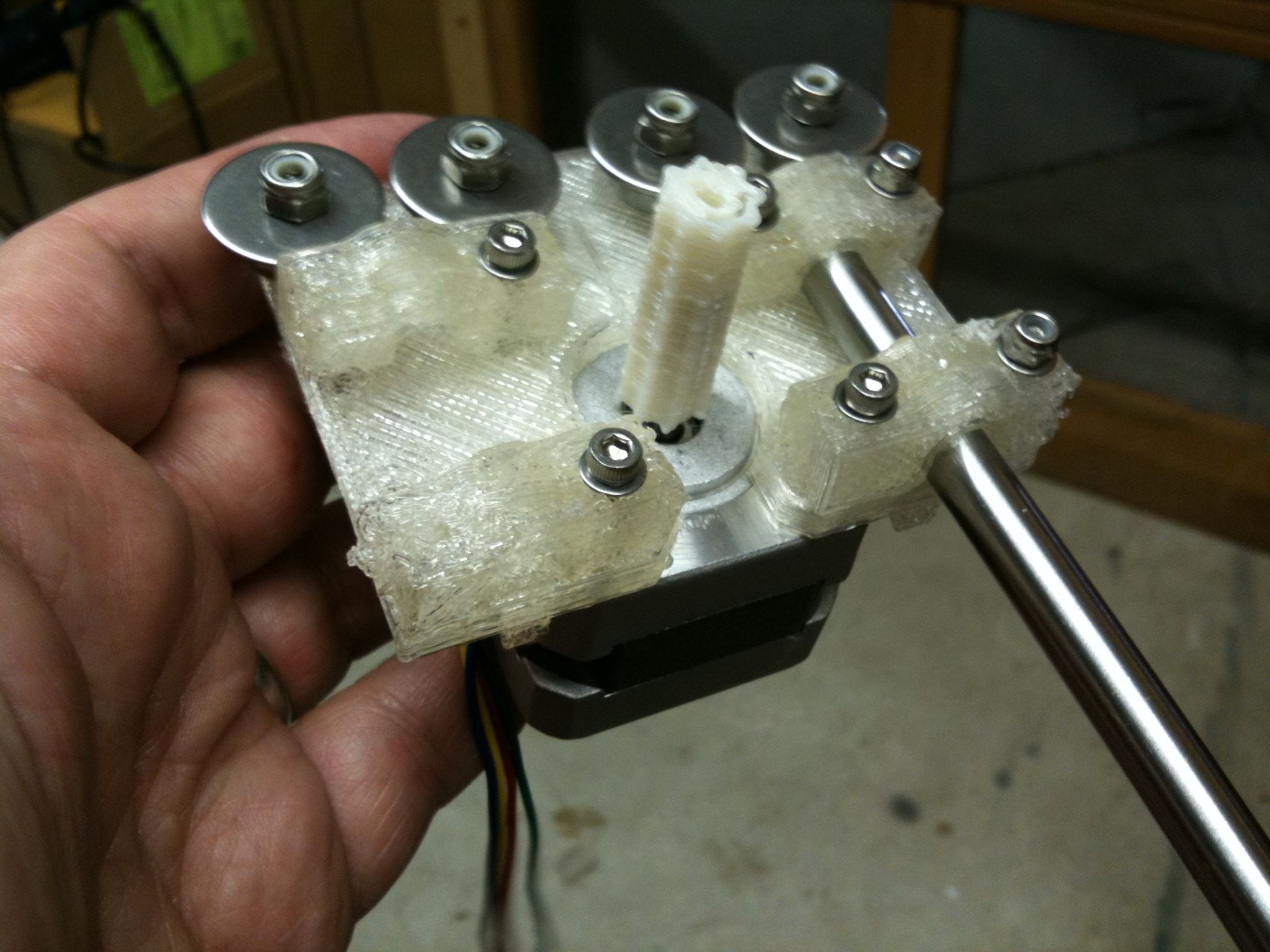
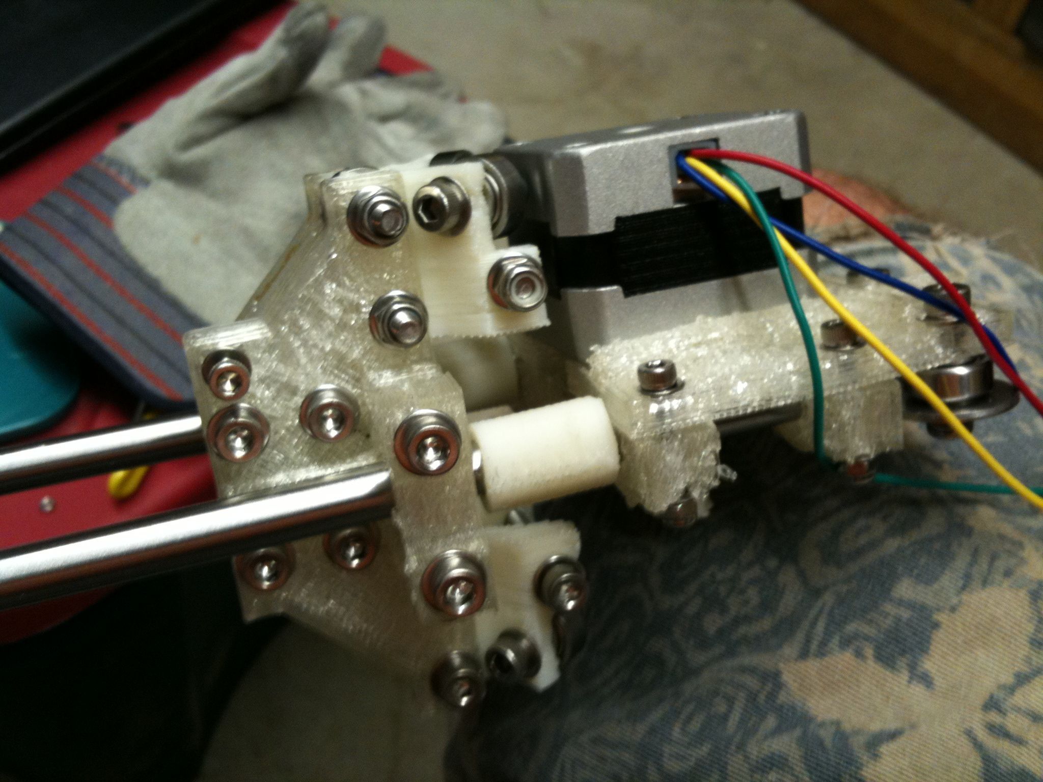
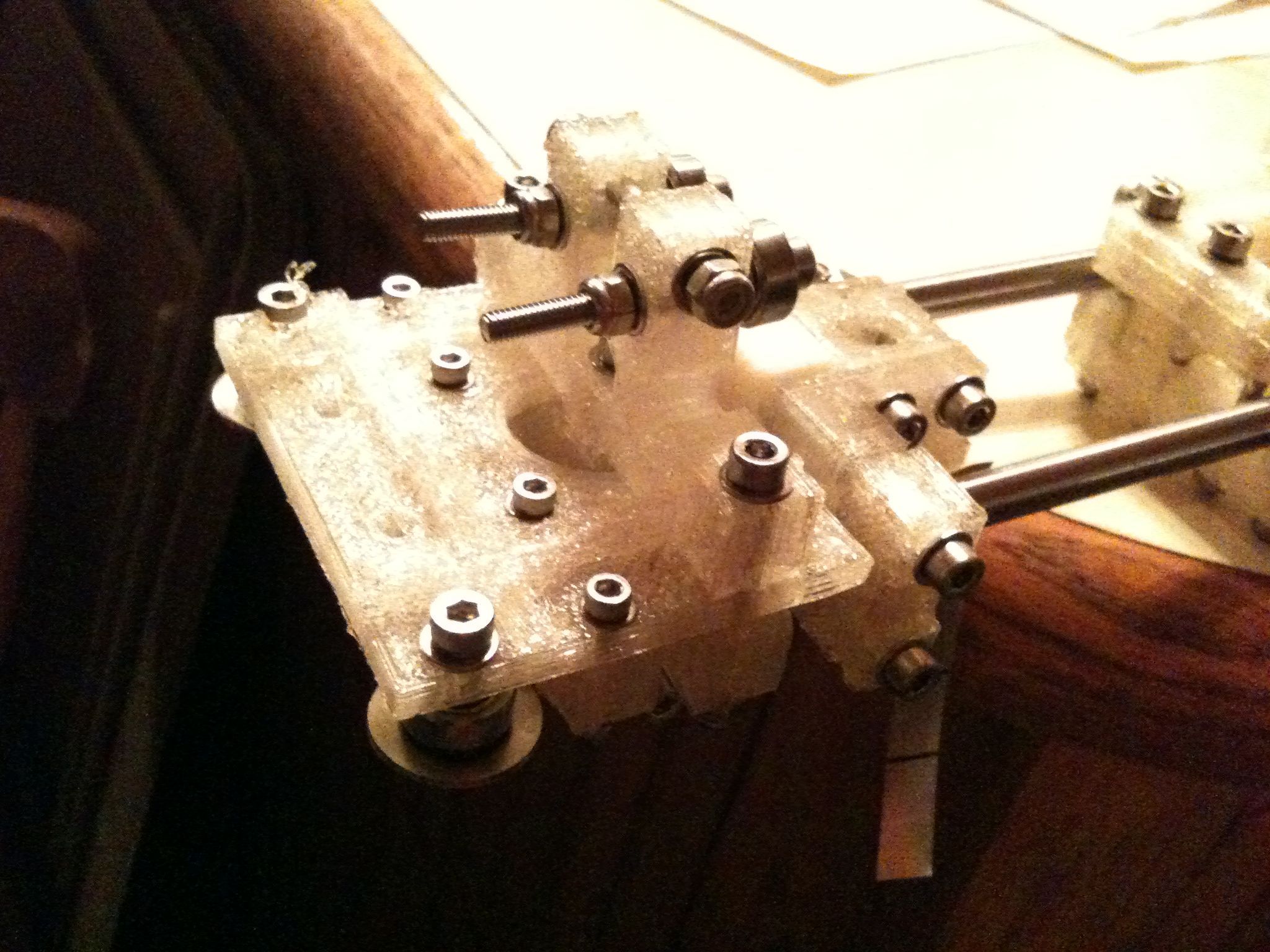
I’ll cut to the chase and show the final pictures first. Here is my mostly completed X axis assembly:
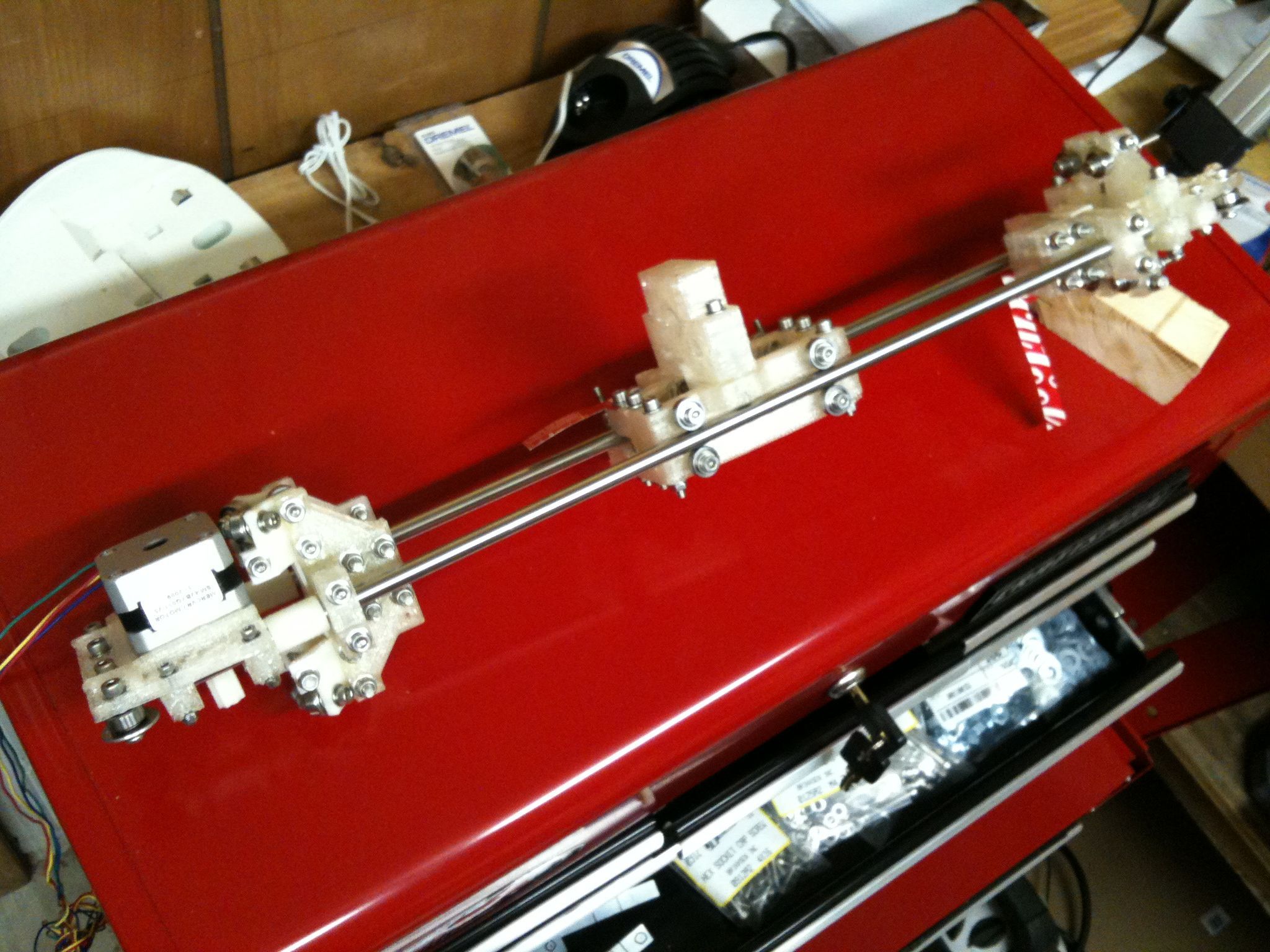
I still need to put on the belt, PTFE, and heater barrel. Six of the nuts on the carriage are still temporary regular nuts, whereas all of the others that are supposed to be nylock are now nylock.
Here are some of the pics leading up to that completed X axis.. (sorry that there aren’t more captions or descriptions – I’m trying to spend more time building than blogging.. 🙂 )
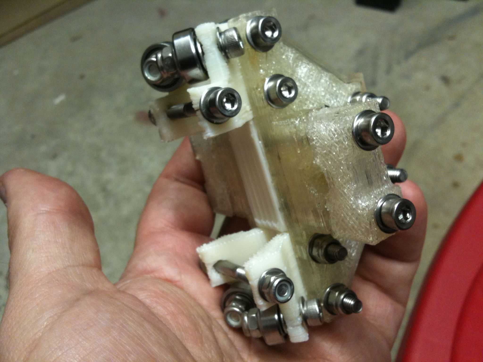
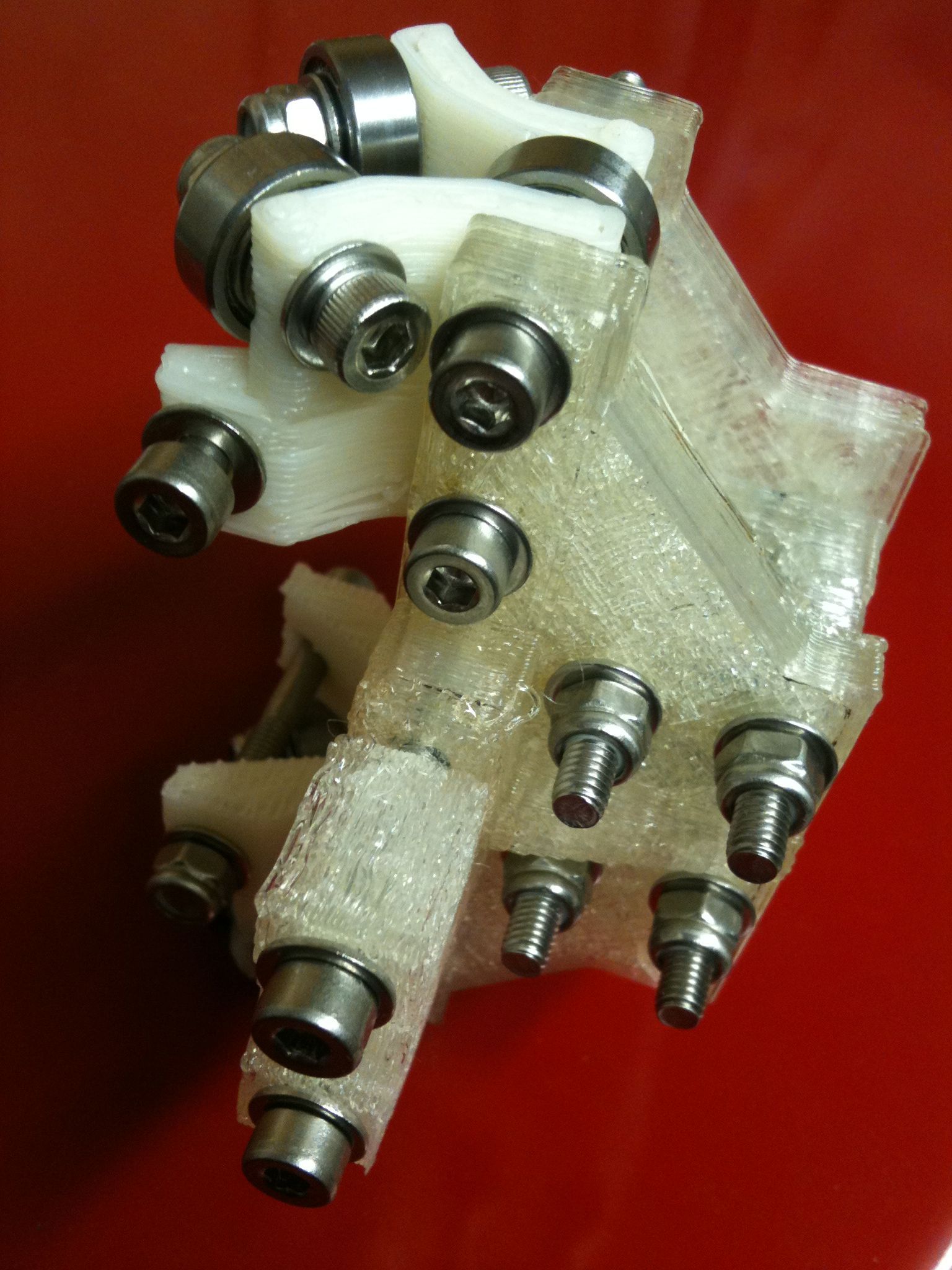
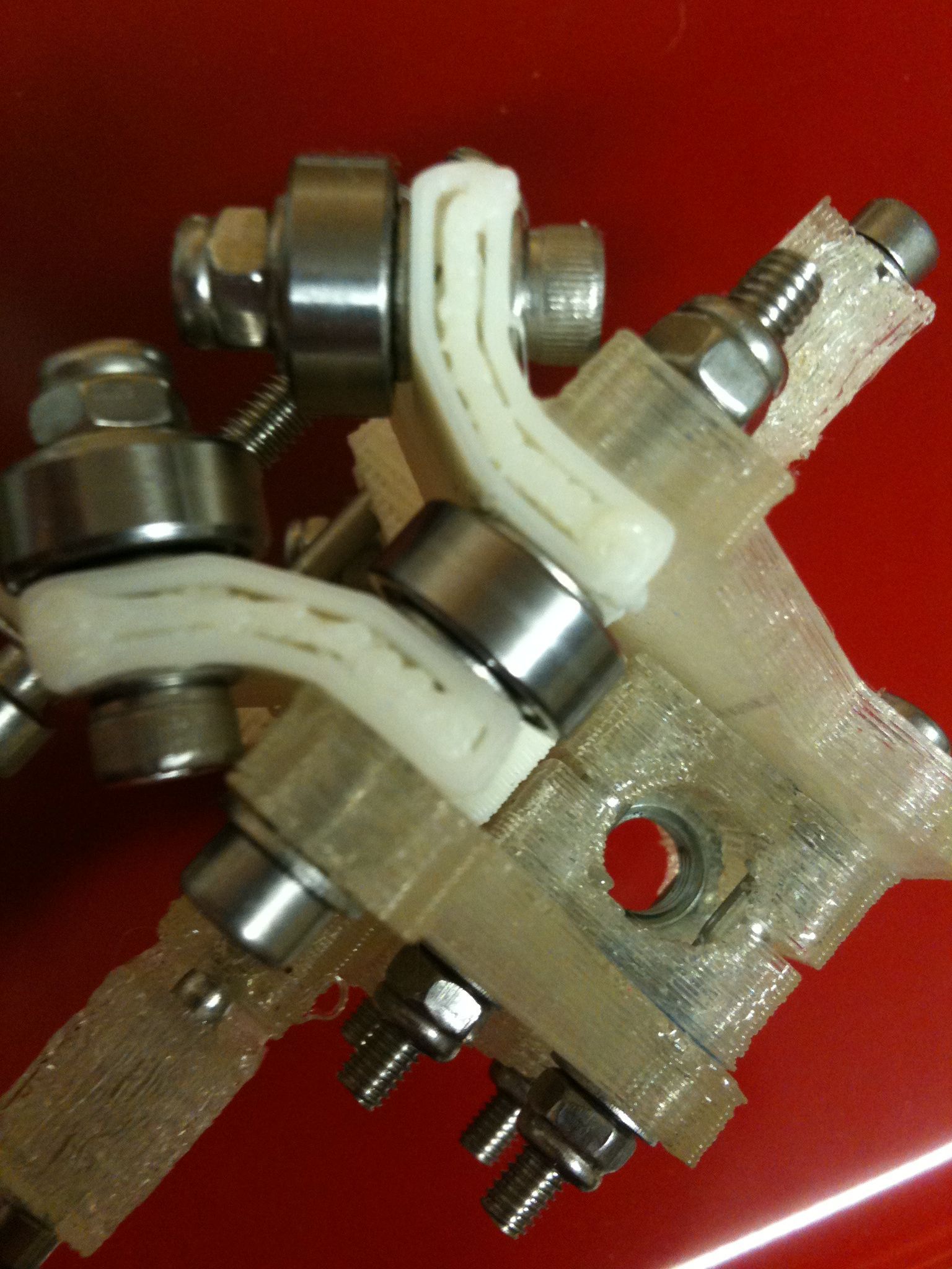
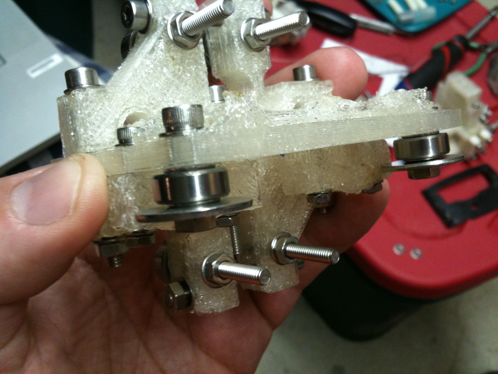
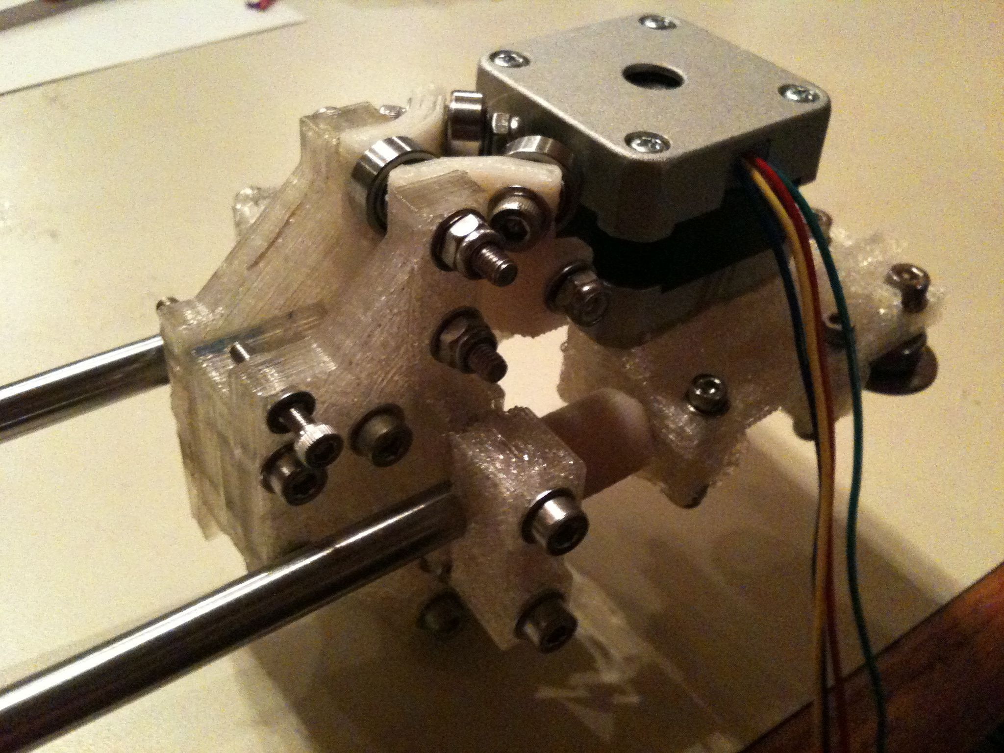
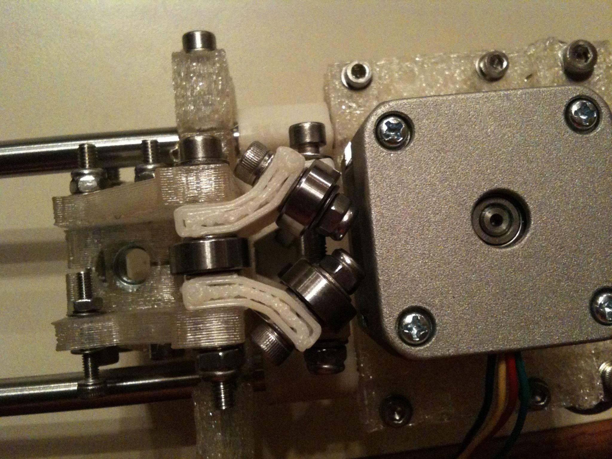
FIrst, here are pictures of the Vert Bearing 360 assembly:
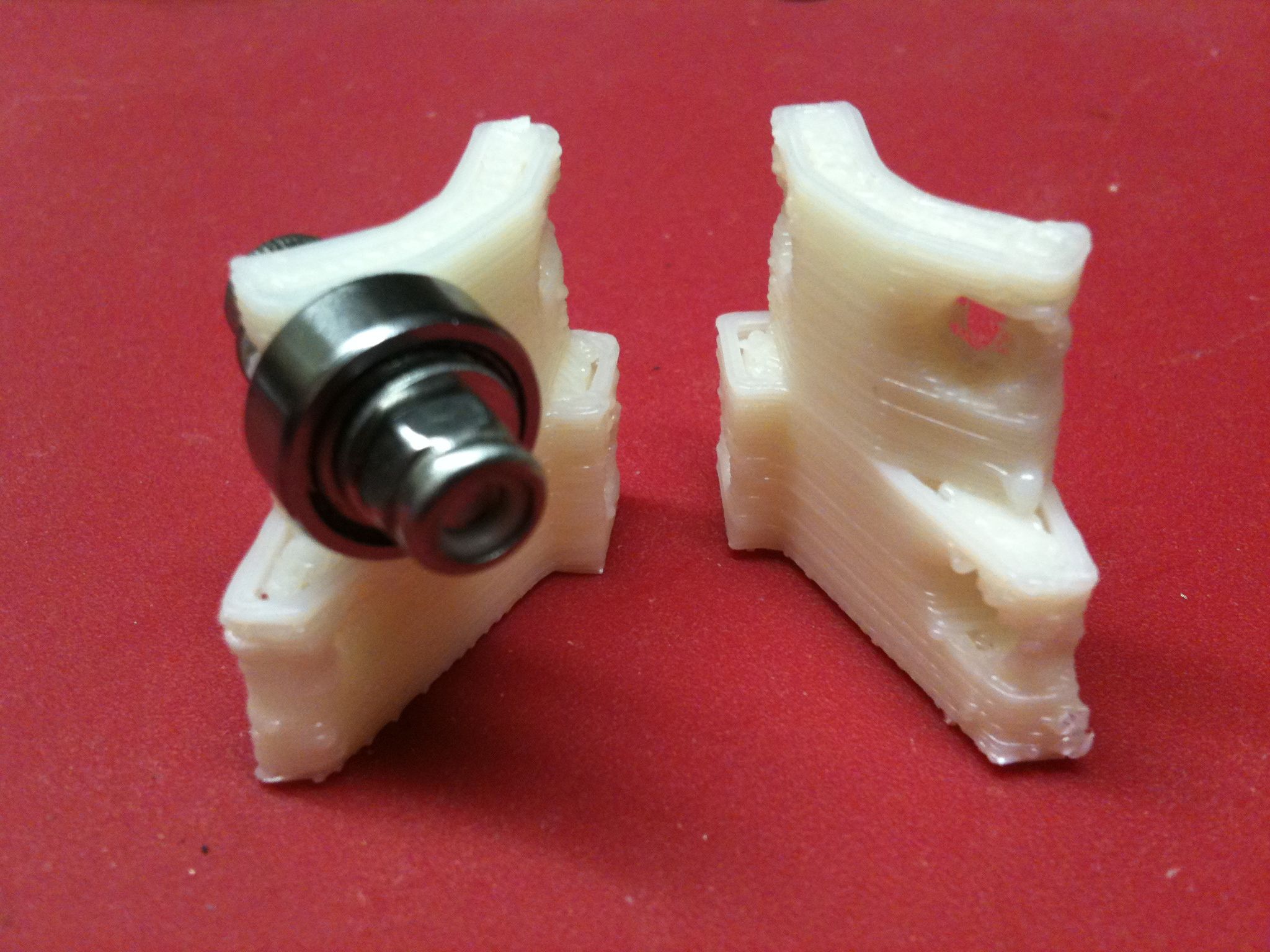
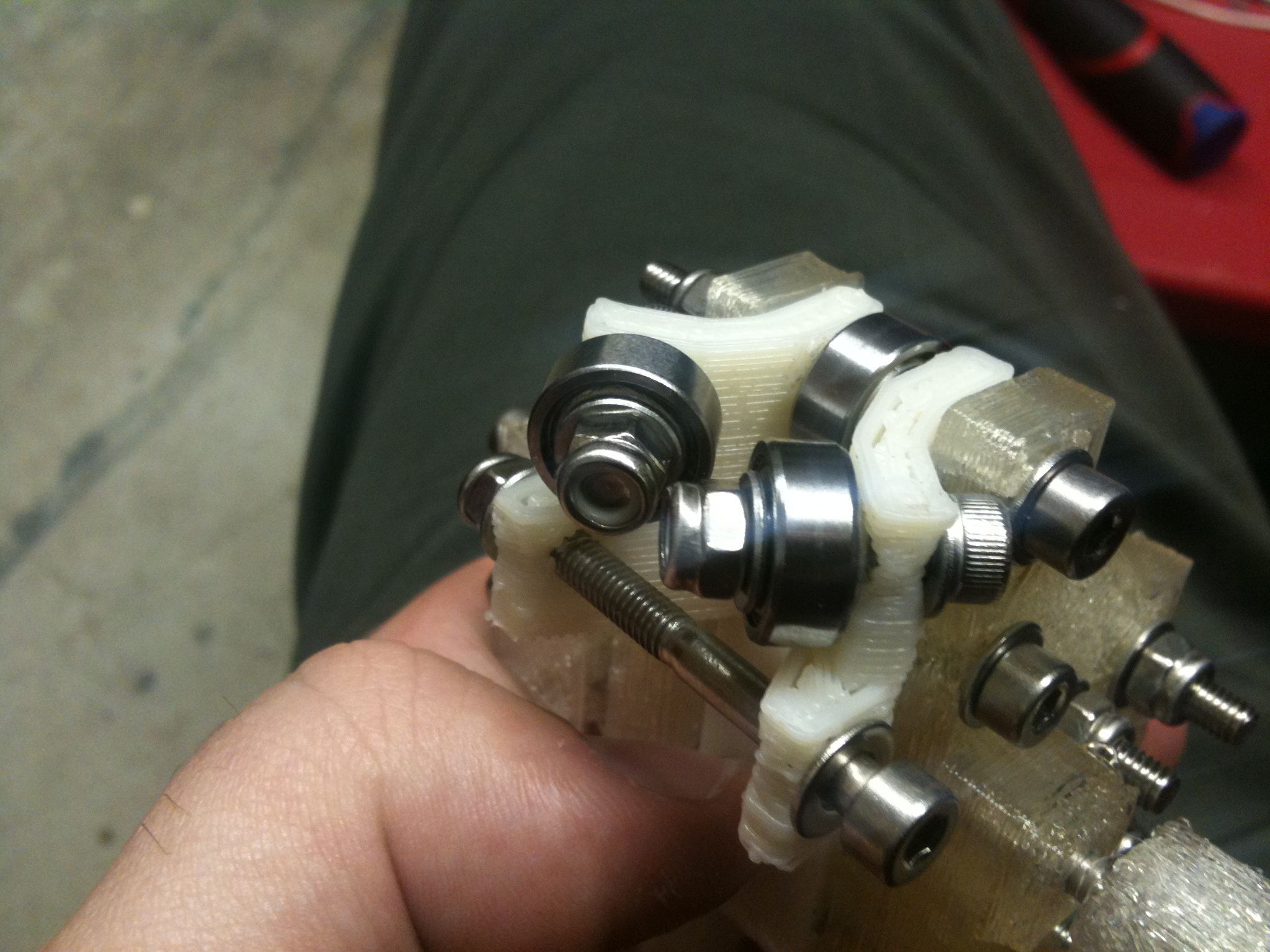
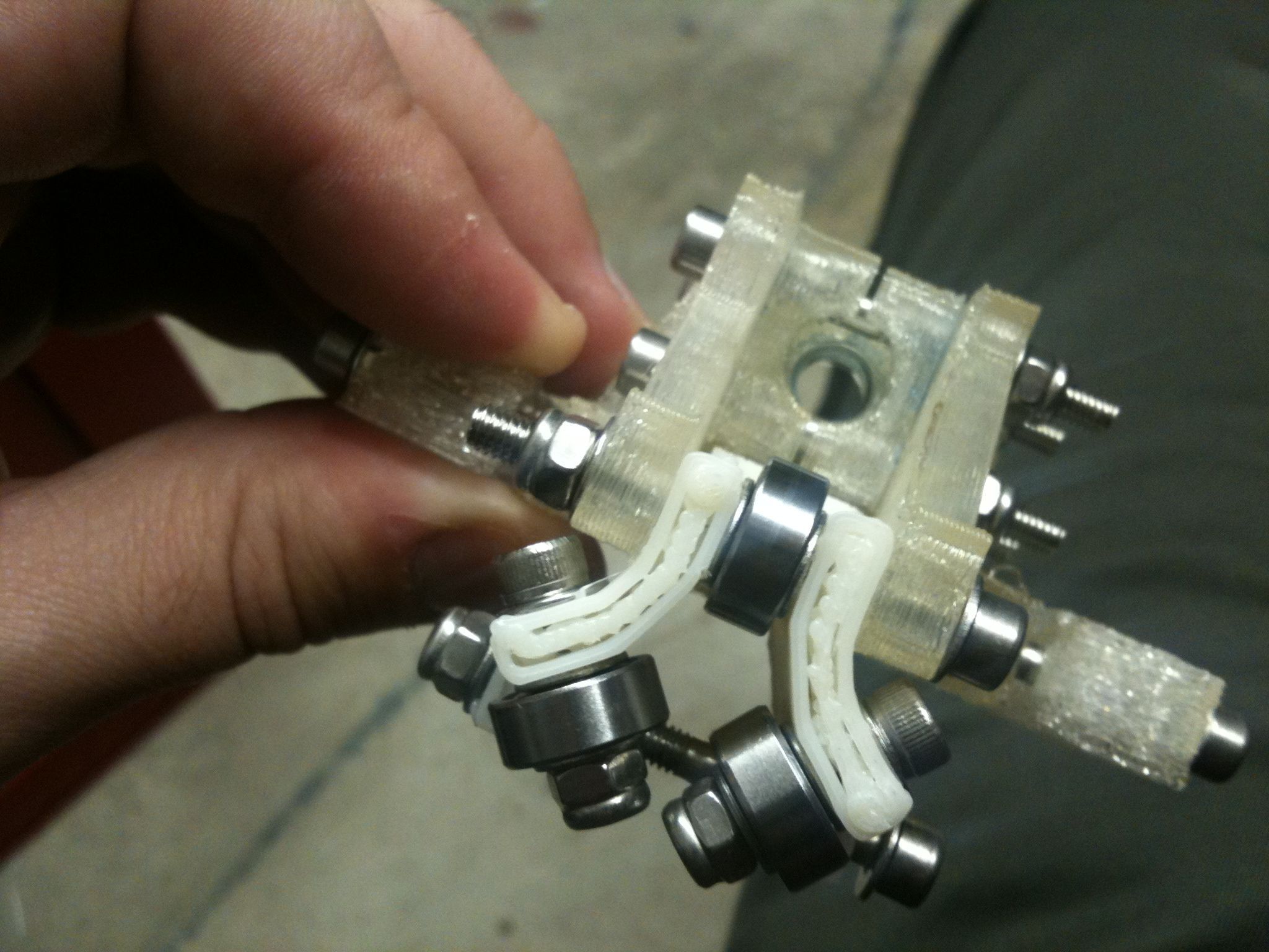
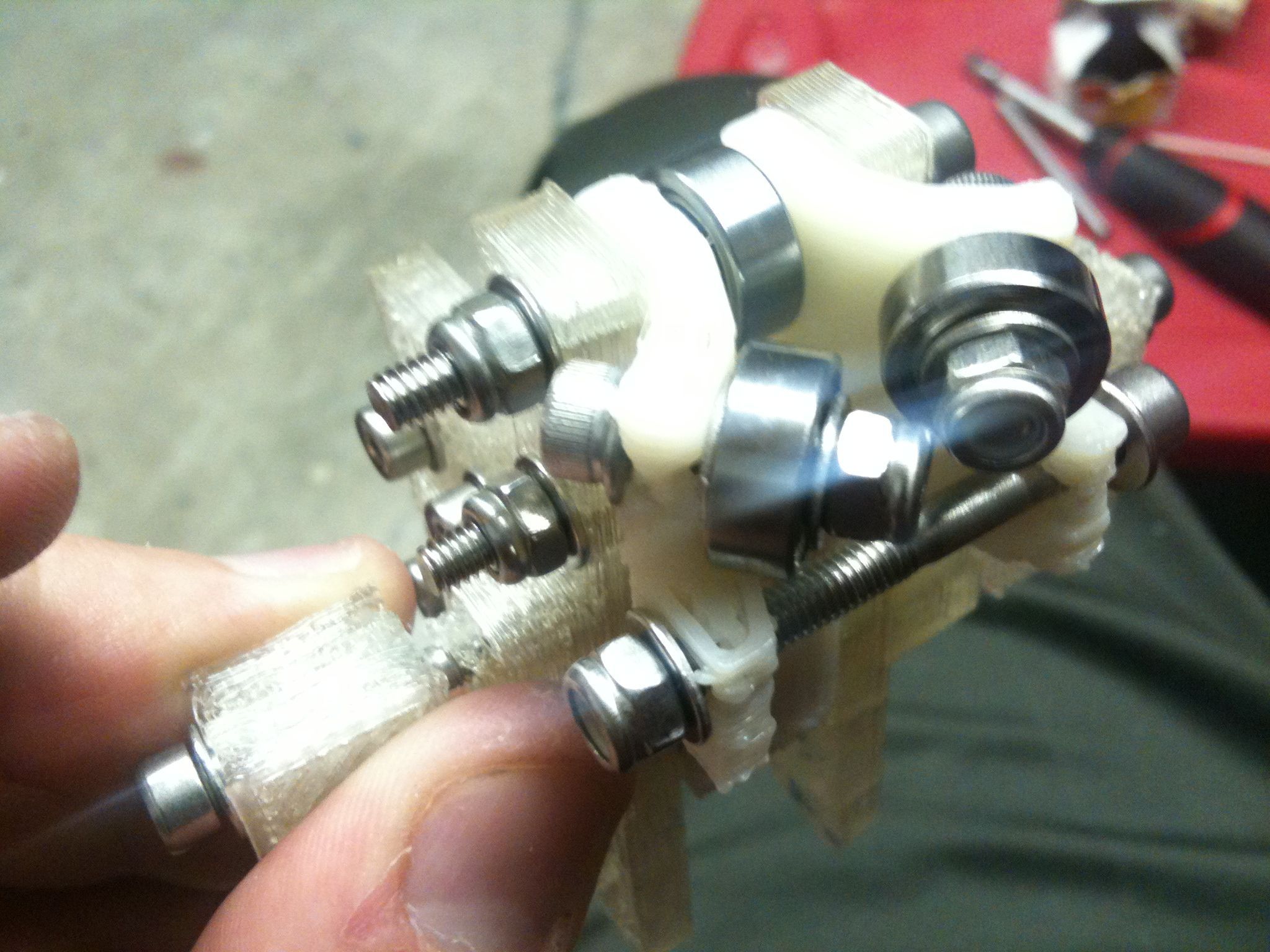
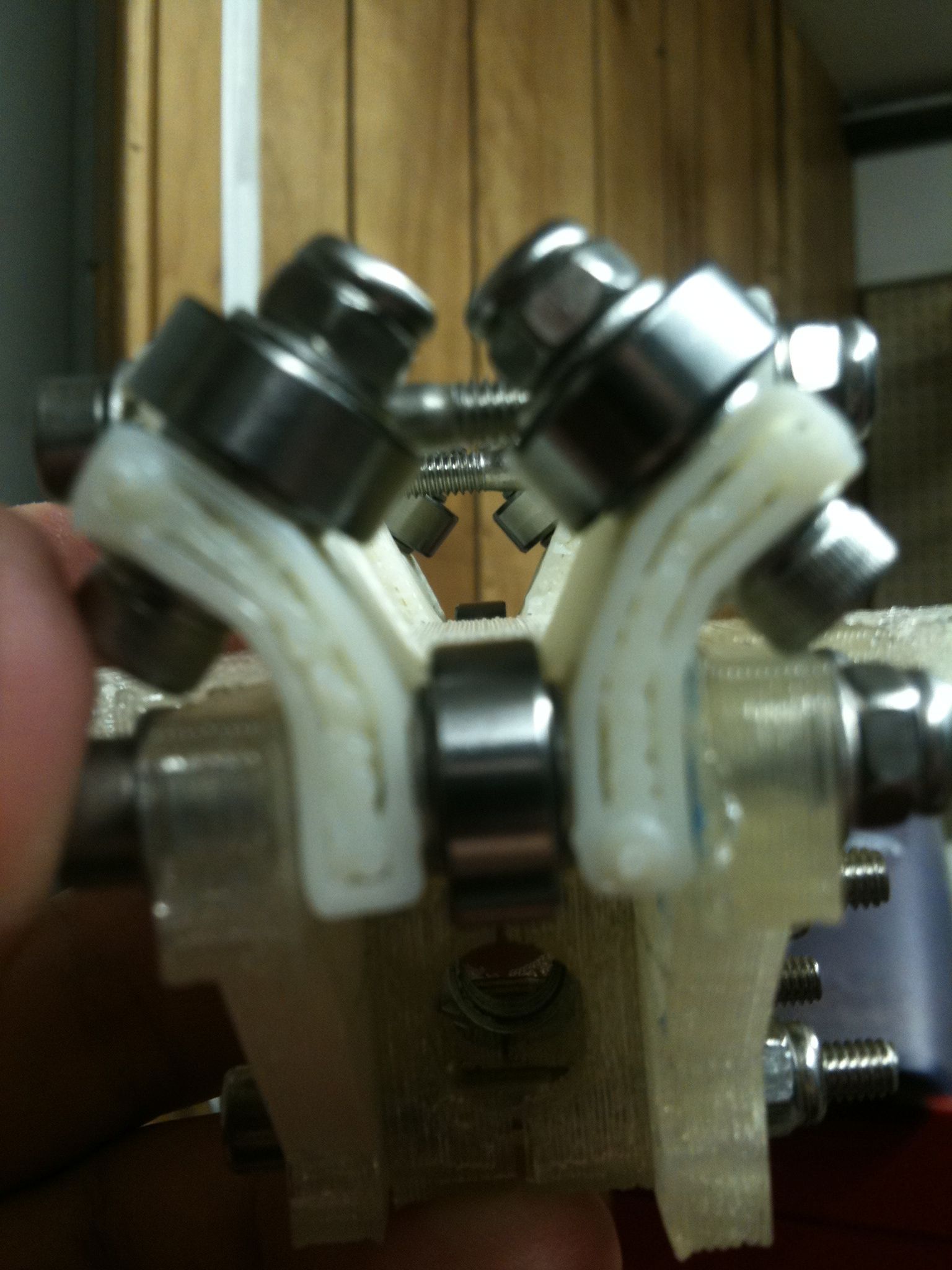
I really like this next pic:
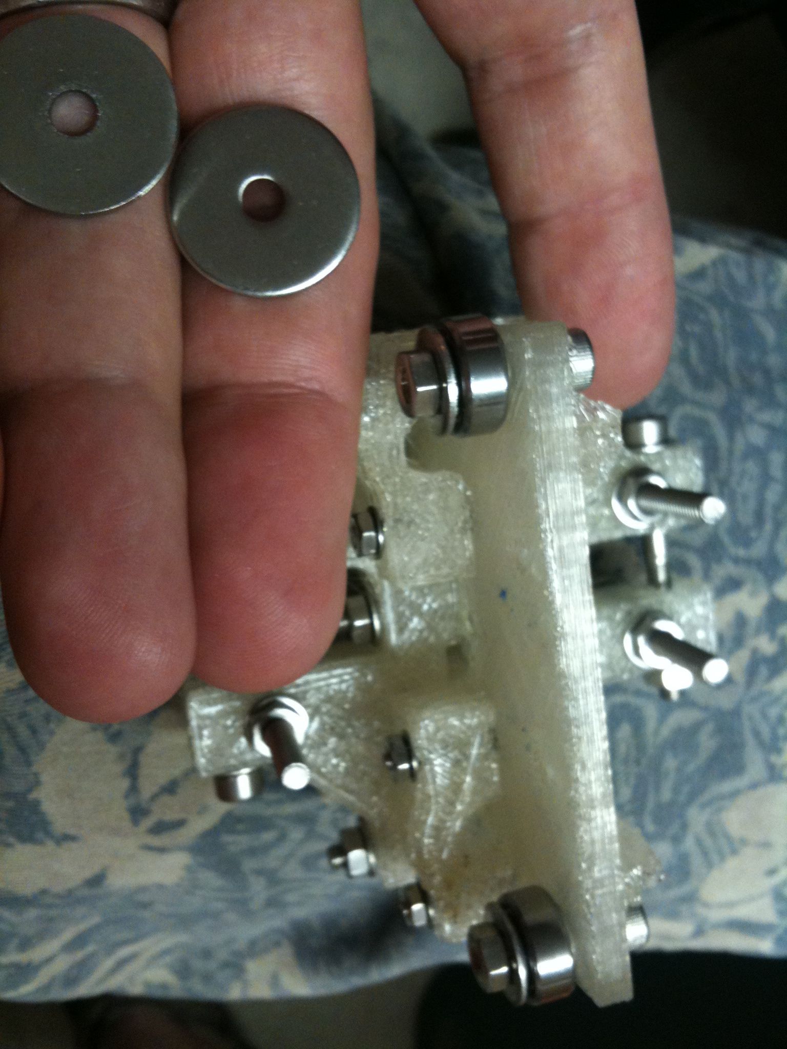
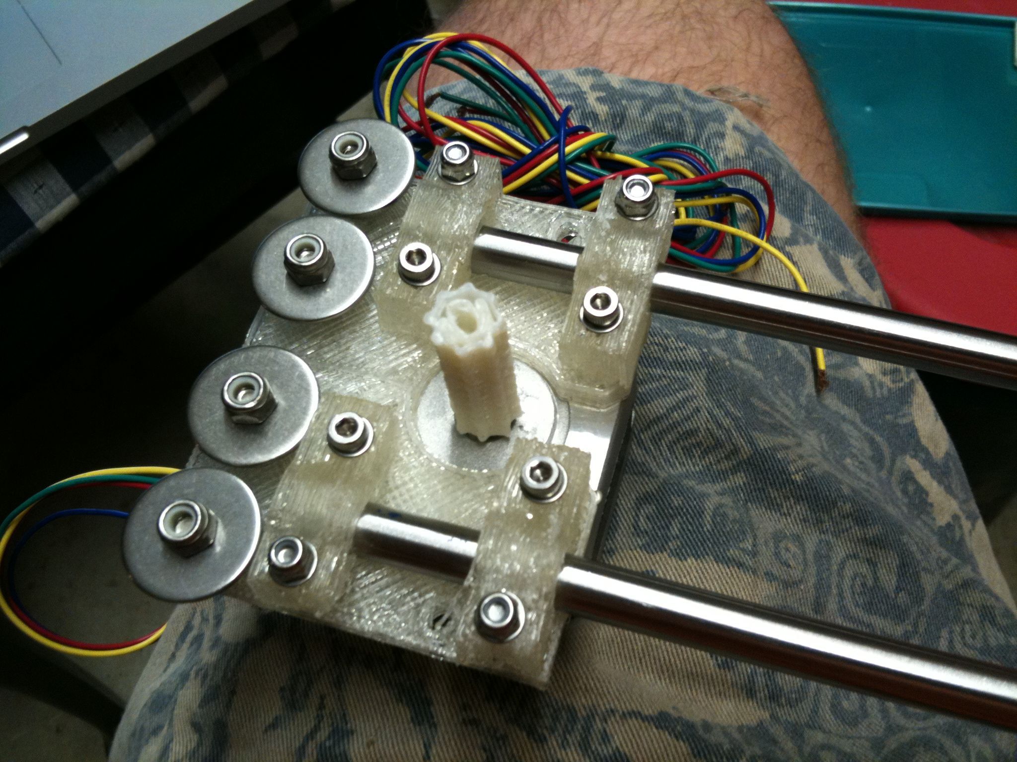
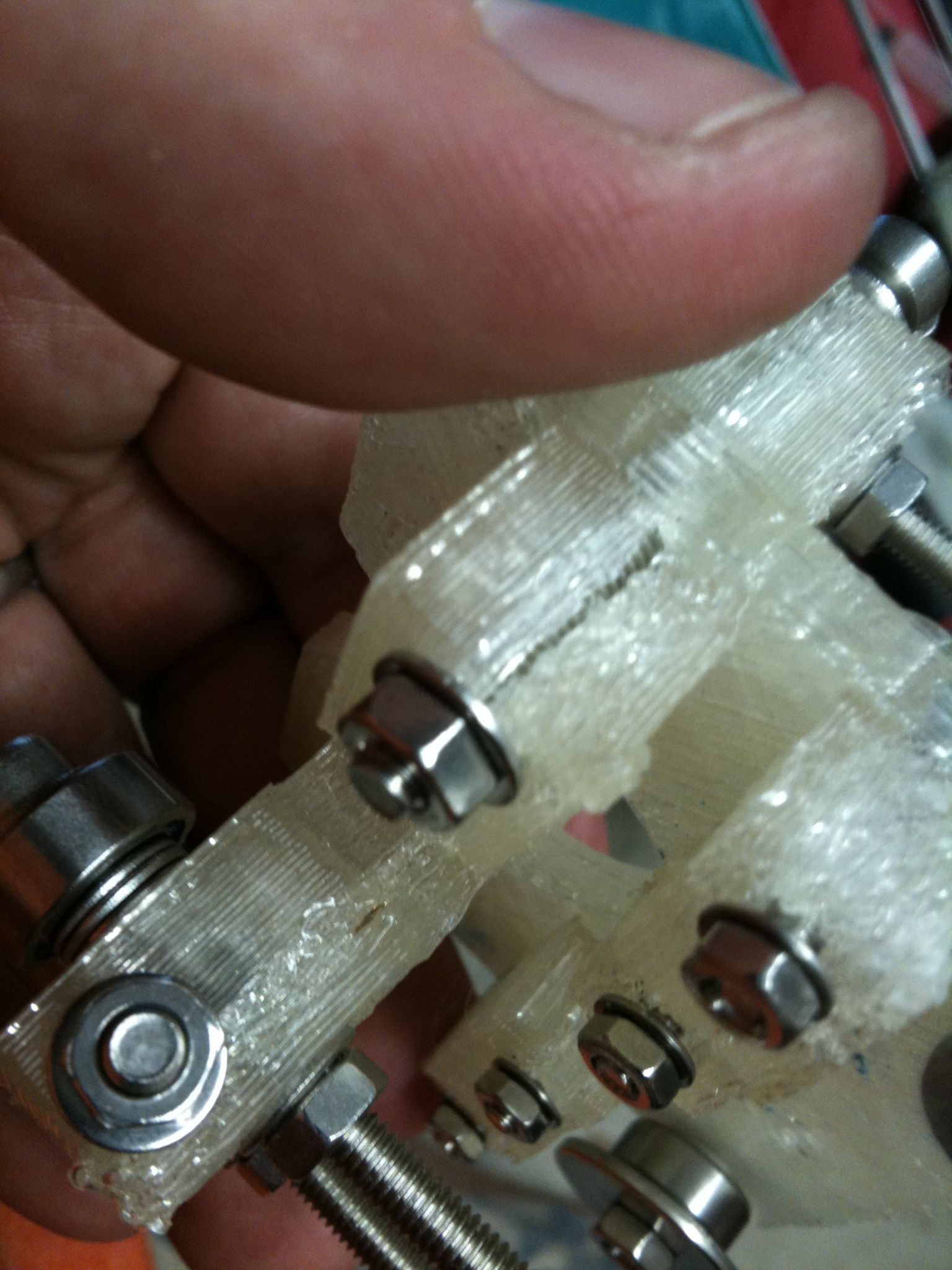
Ok, so when I ordered parts, the “mudguard washers” I originally obtained were way too small. The whole point was that they were supposed to extend out far to hold up a timing belt. I finally found a source (not McMaster) that had mudguard washers (fender washers) of the right size. These next two pics show the new washers and them in their correct place.
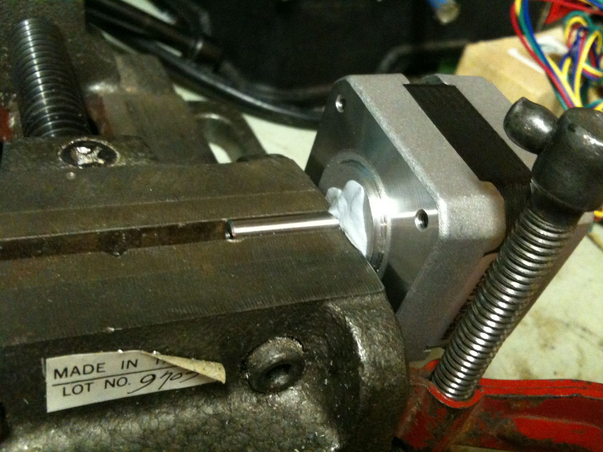
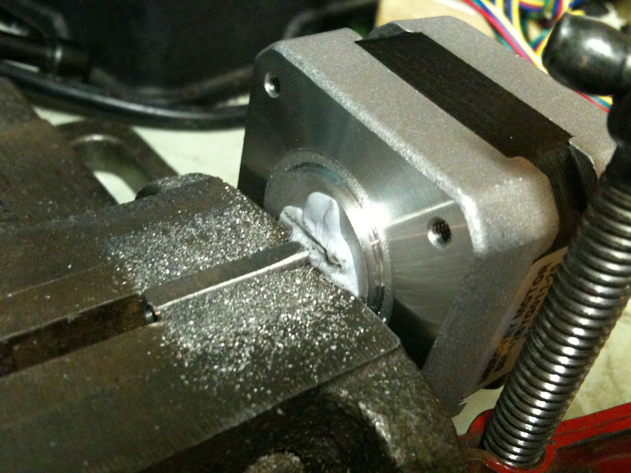
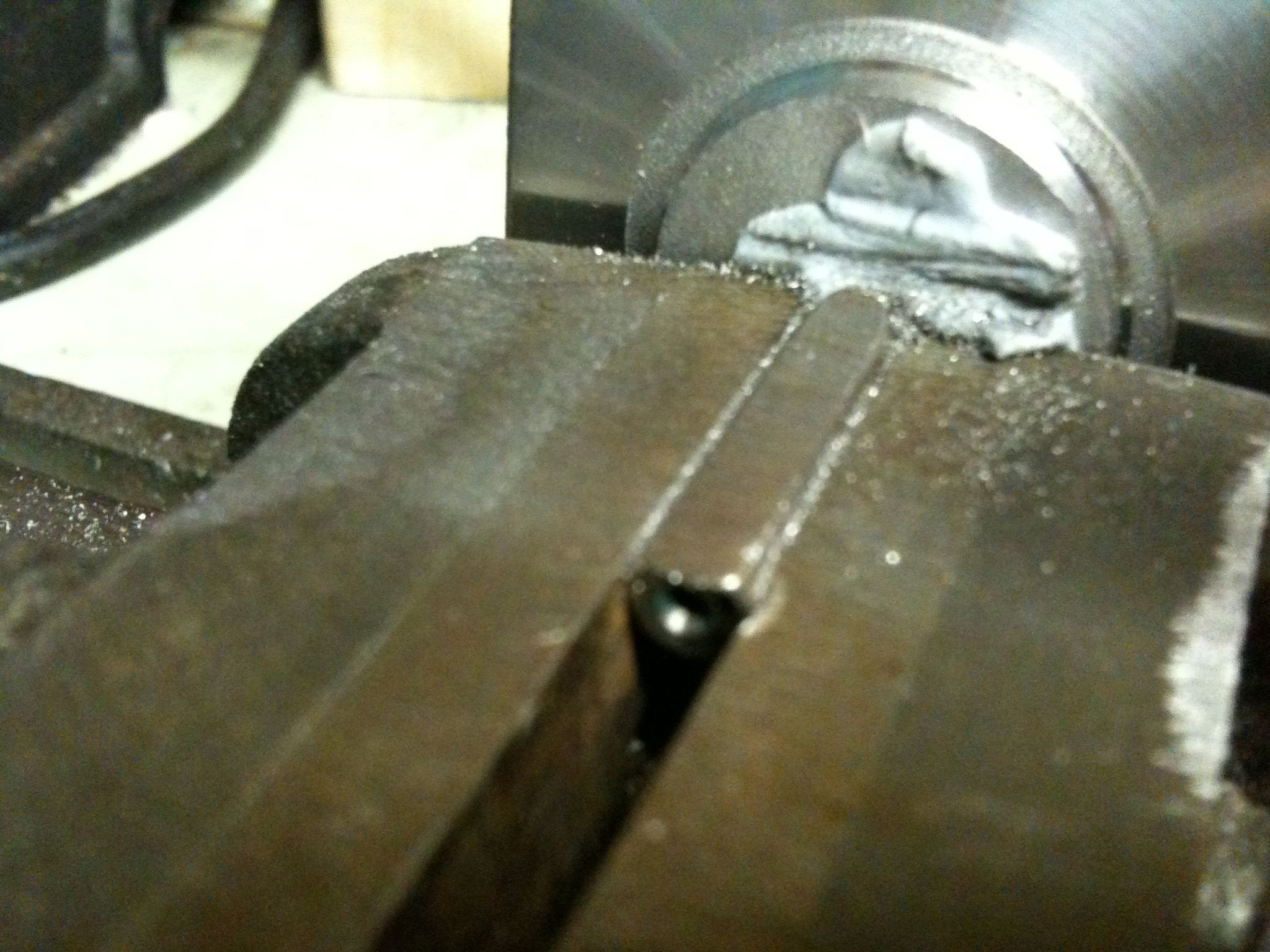
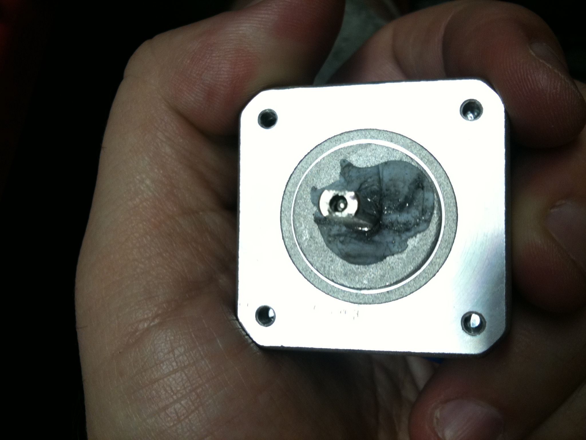
Ok. So next, there are pulleys that need to go on the stepper motor shafts, the insides of which have oval/rectangular holes intended for filed-down stepper motor shafts. (There are now some good alternatives on thingiverse that don’t require as much filing, but I’m not in a position where I can print new parts right now). So, I filed down the shaft on one of the stepper motors (and I’ll do the same for the next two soon). Here I clamped the shaft in a vise, after caking the base of the shaft in blue-tack, which is something like silly putty, to keep steel filings from being pulled directly into the stepper motor (it’s a big magnet, remember?).
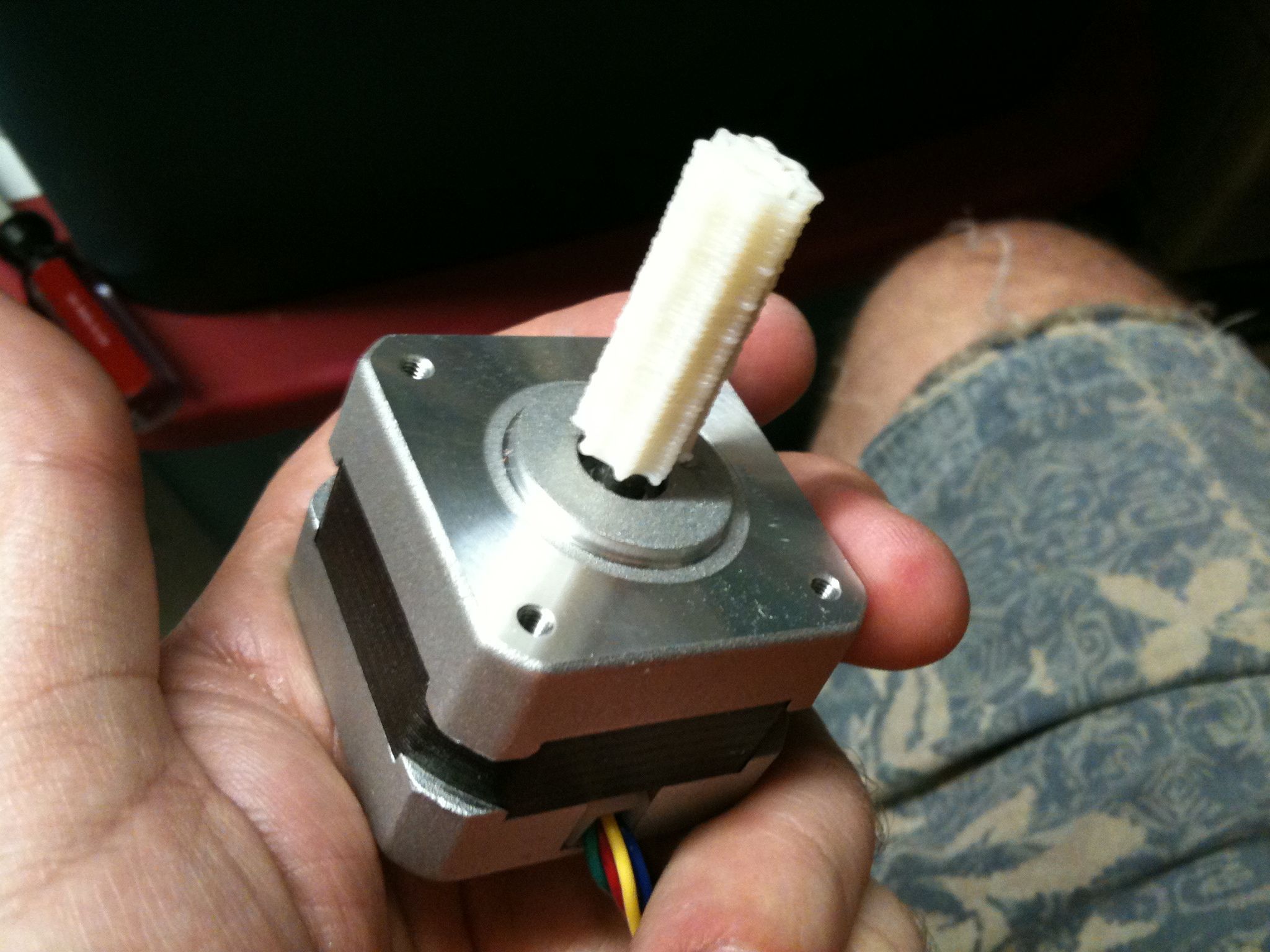
Then, a few Dremmel cuts later and after lightly tapping with a plastic mallet (with the base of the stepper shaft supported by a clamped small hex socket), I managed to get the pulley on the shaft!
Here’s a ridiculously short 5-second video showing that:
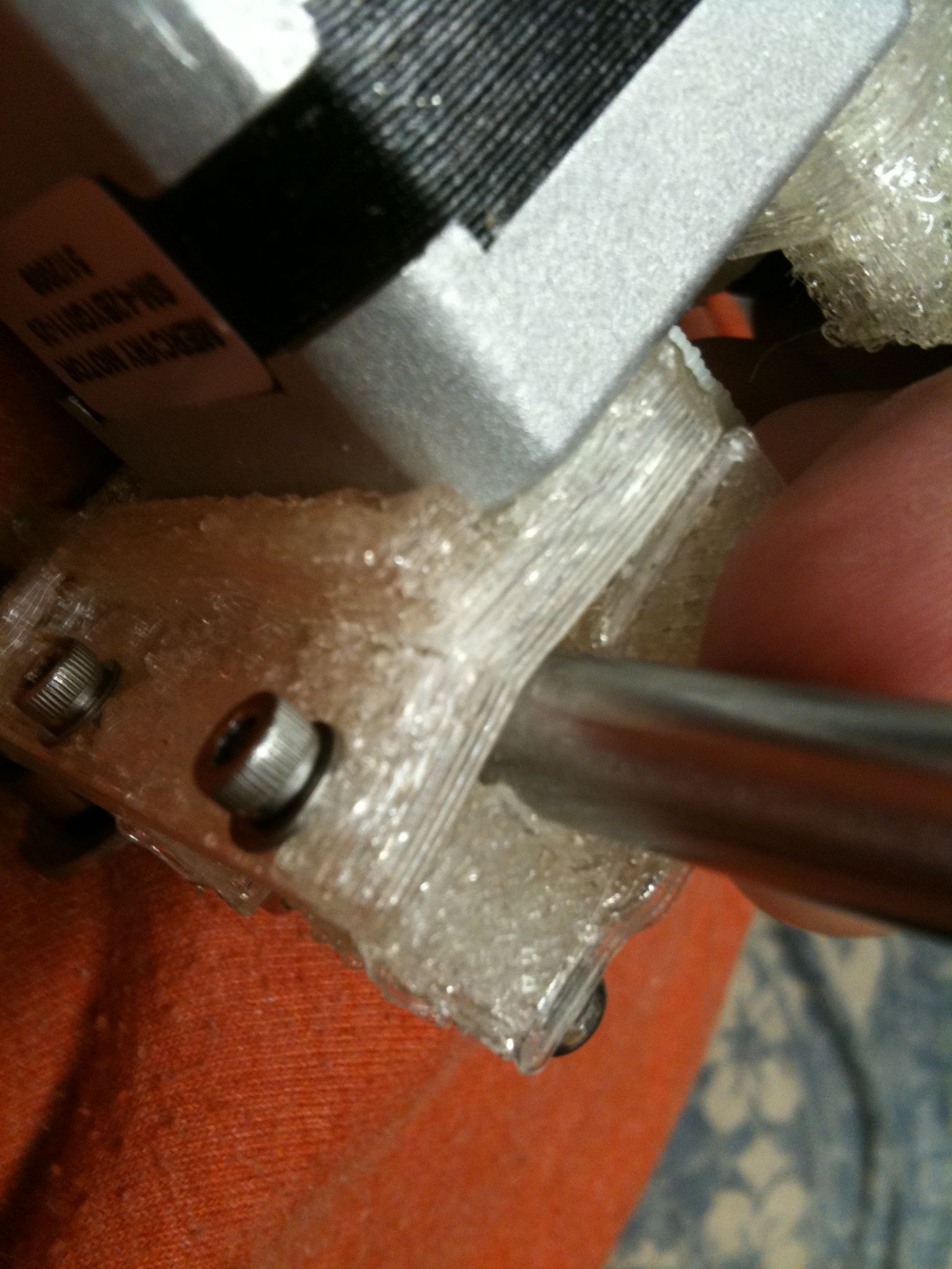
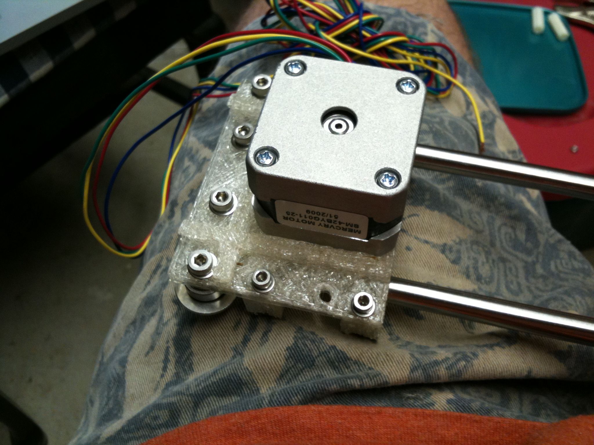
So then I moved onto the motor bracket. Unfortunately I think I tightened one side of a clamp too much (on the rest of them I carefully went one side to the other), resulting in a crack in this piece (visible in this picture). Hopefully it doesn’t make that much of a difference in the end:
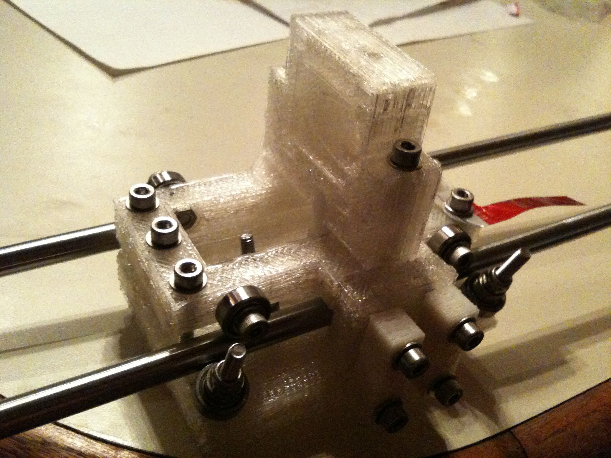
So I continued.. Here is the bottom of the motor bracket, with one of the two x-axis rods in place:
Then the top and bottom once the second rod was placed:
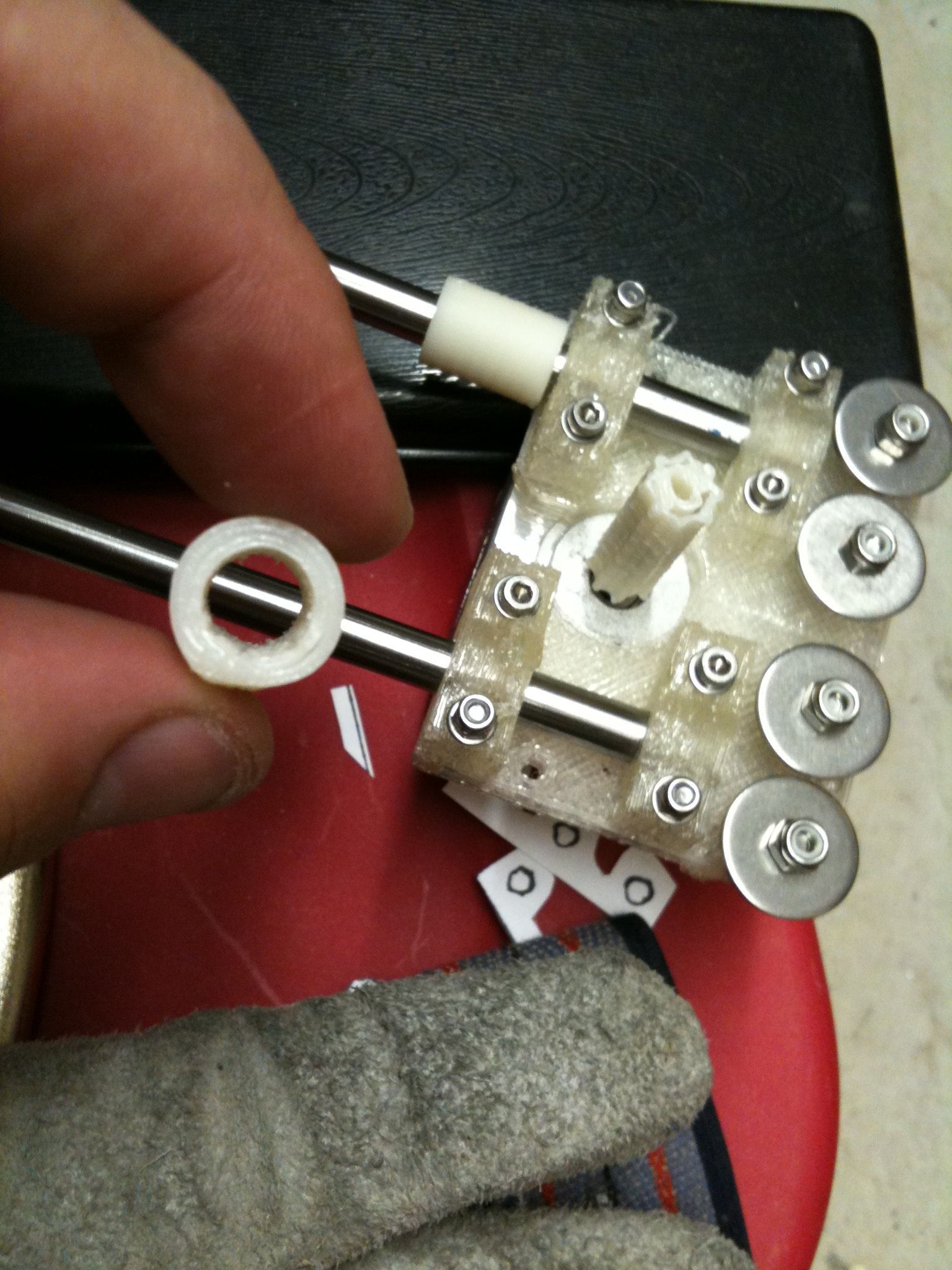
Here are two cylindrical spacer pieces that go next along the rods:
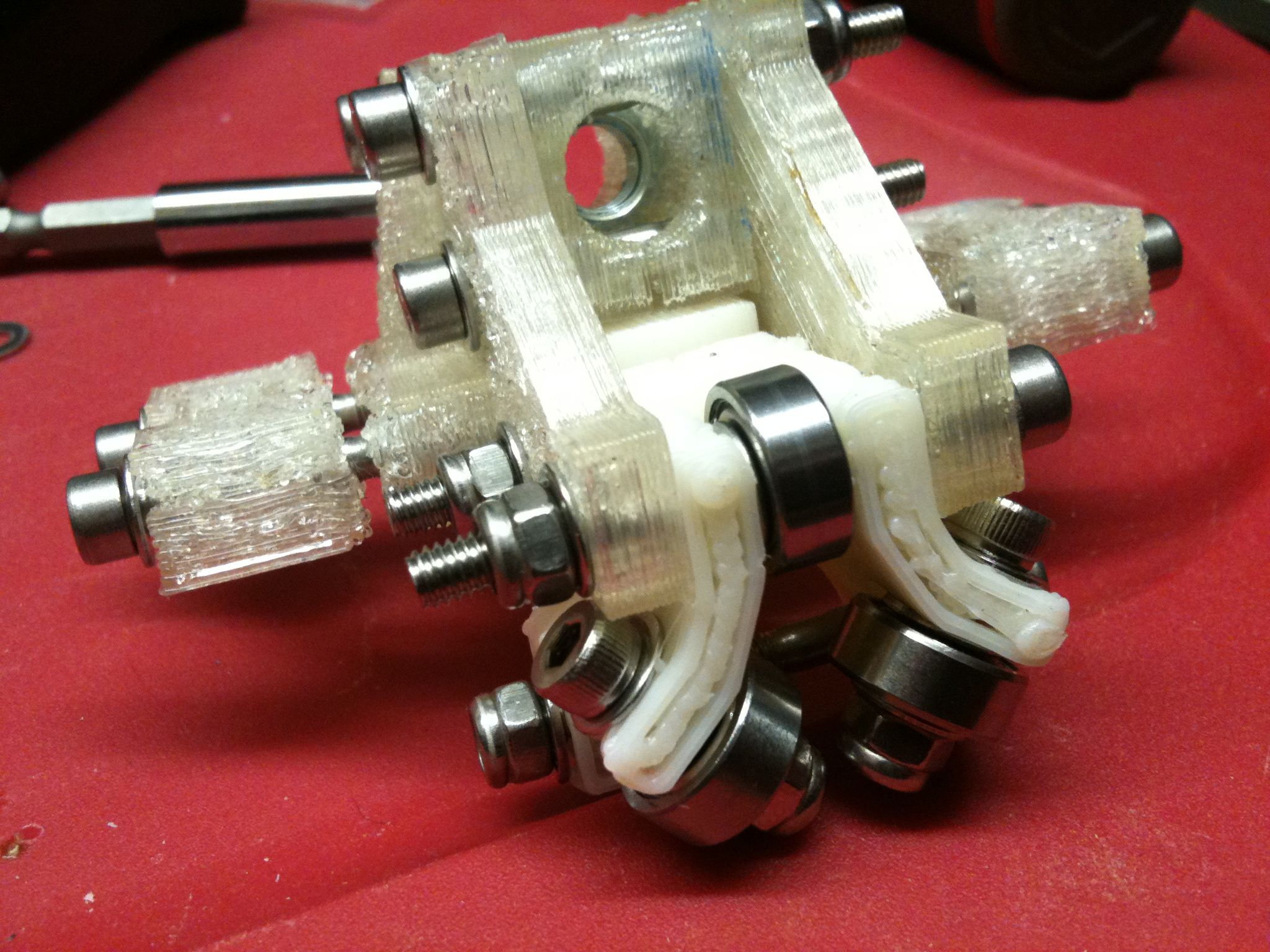
Next on the x axis rods, I placed the Vert Bearing 360 assembly shown earlier in this post:
Here’s another crack that doesn’t seem like it will be a problem:
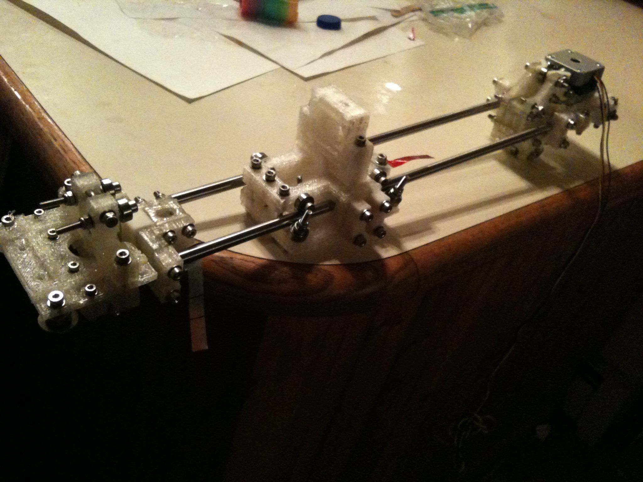
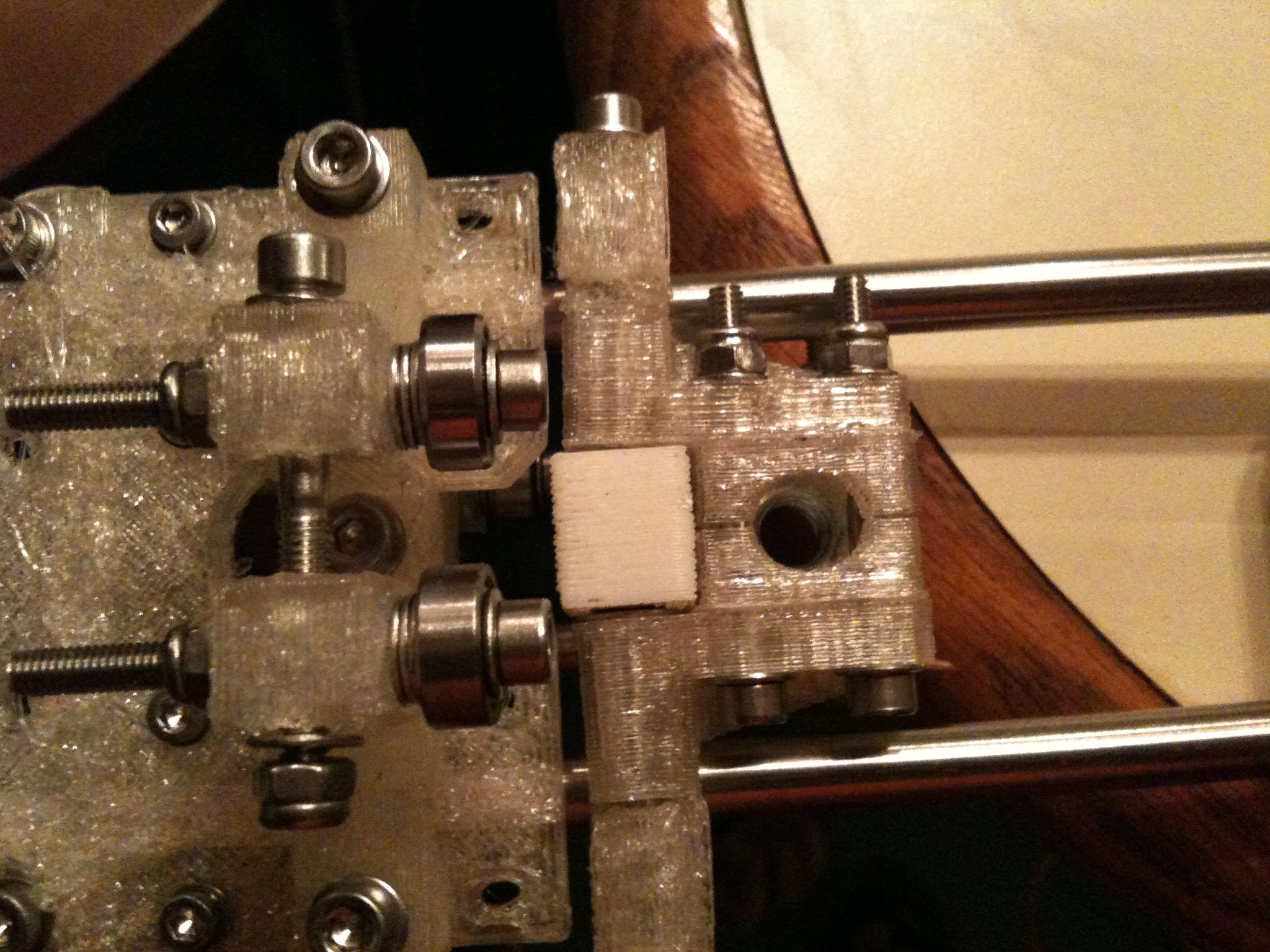
And finally, here are the first two pictures of the assembled X axis again, along with other closeups. Sorry about the horrible lighting – I should take some of these outside or something.
Can’t wait until I get some free time to move onto the next steps. I might not get free time until Monday night though.
Getting closer!
p.s. I’m thinking that maybe I need to replace those thin sheets with pieces of tin or something – I hope not.
free double diamond slots https://2-free-slots.com/
888 free slots machine https://freeonlneslotmachine.com/
free slots games egypt https://candylandslotmachine.com/
sharknado slots in vegas https://pennyslotmachines.org/
ff7 cait sith slots limit https://slotmachinesworld.com/
free vegas igt slots https://slotmachinesforum.net/
caesars free slots online https://slot-machine-sale.com/
mail slots https://beat-slot-machines.com/
armor slots https://download-slot-machines.com/
888 free slots machine https://411slotmachine.com/
google free slots https://www-slotmachines.com/
spooky slots 2015 https://slotmachinegameinfo.com/
doctoral dissertation https://buydissertationhelp.com/
doctoral dissertation help thesis https://dissertationwriting-service.com/
best dissertation https://help-with-dissertations.com/
dissertation online https://mydissertationwritinghelp.com/
dissertation acknowledgements https://dissertations-writing.org/
example of a dissertation https://helpon-doctoral-dissertations.net/