Meta
Pages
Twitter!
-
Recent Posts
- Migrated to new hosting provider
- My first full February-Full-of-3D-Prints (FFo3DP)…
- Four, no, 45 months.. part 21 of ?
- Giving the MoS their RepRap – Four, no, 45 months.. part 20 of ?
- Four, no, 44 months.. part 19 of ?
- The Abacus – Four, no, 44 months.. part 18 of ?
- Don’t make carriages out of PLA – Four, no, 39 months.. part 17 of ?
- Four, no, 37 months.. part 16 of ?
- Four, no, 33 months.. part 15 of ?
- Quadcopter! Four, no, 32 months.. part 14 of ?
- Four, no, 32 months.. part 13 of ?
- Four, no, 32 months.. part 12 of ?
- Science! – Four, no, 31 1/3 months.. part 11 of ?
- Four, no, 31 months.. part 10 of ?
- The Kevin Post – Four, no, 28 months.. part 9 of ?
Archives
- February 2019
- February 2015
- September 2014
- August 2014
- March 2014
- February 2014
- September 2013
- August 2013
- July 2013
- May 2013
- March 2013
- October 2012
- September 2012
- March 2012
- February 2012
- October 2011
- May 2011
- April 2011
- January 2011
- December 2010
- November 2010
- October 2010
- September 2010
- August 2010
- July 2010
- June 2010
- May 2010
- April 2010
- March 2010
- February 2010
- January 2010
- December 2009
- November 2009
Monthly Archives: October 2010
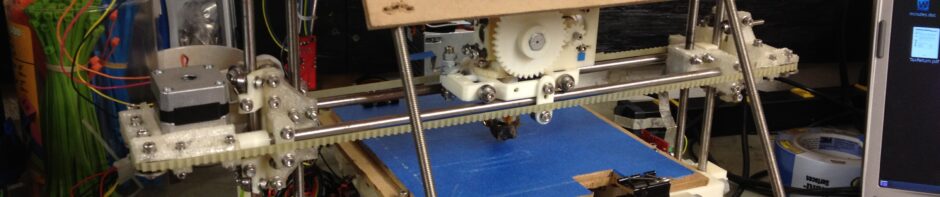
One Year
On October 29th, 2009 (one year and two days ago), I threw my hat over the wall and spent $180.00 on electronics for my Mendel RepRap. This has easily been the coolest thing I’ve ever built. It’s been unbelievable fun, … Continue reading
Posted in MyRepRap
291 Comments