Archive for July, 2013

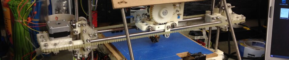
Science! – Four, no, 31 1/3 months.. part 11 of ?

Saturday, July 27th, 2013

Here we go..

In my last post I had printed out two sets of RepRap parts for new RepRap printers.

The set on the right was a birthday present for my brother Jon, and the set on the left was to become a 2nd printer for me. But as I mentioned, I re-purposed that set that was initially made for me, and built it for someone else. We’ll talk about who in this post.

(Lots of pics in this post.. don’t quit mid-way – even if you’re not into the printer details, make sure you make it to the end, even if just to answer the end of that last paragraph).

As I’ve had to do for the past 11 posts or so, I have to remind you all again, I’m about a year and a half behind. Today is July 27th 2013, but I’m posting about events starting on January 28 2012.

So by January 13th 2012 we had solidified a date for the first meeting of the New England RepRap group: February 26th, 2012. We mailed it out on a bunch of different forums and on our old Google Groups list. The idea would be to have a bunch of people bring their RepRaps (or lesser, non-self-replicating printers 😉 ) to one place, set them up, and have an excuse to print for the whole day.

We were having trouble finding a good location, so I offered the use of my house. Initially I wasn’t sure what to expect.. I thought there was a good chance it could be awesome, but feared the possibility that it might just suck. Wow was it ever the former – everyone who came was really glad to attend, and wanted to know when the next one was.

But before that, someone named Julia from the Museum of Science in Boston sent out a few emails looking for people who might be willing to lend the museum their 3D printers. The Museum was planning a three-week exhibit on 3D printing.

I practically grew up in the Museum of Science – we went as kids like fifty times at least. Anyone remember this commercial from the 70s?

The net that Julia cast hit me from two directions – she sent mail on our thread about the New England RepRap meetup, and she sent mail to MIT alumni (which a coworker sent me).

She had asked about borrowing a printer. I told her that I had a self replicating printer, so why didn’t I just make the Museum one for it to keep? I talked about the cost of vitamins (non-printable parts) and said I’d be willing to print them parts, foot the initial bill, build it, get it working, show them how it works, and maybe if they had $ later they could pay me back for the vitamins. They liked the idea a lot.

I ordered some of the vitamins (again, non-printable parts – mcmaster.com stuff like nuts, bolts, and threaded rod) for 4 sets of RepRaps: one set for a coworker, one set for my brother, one set for my eventual 2nd RepRap, and one set for the Museum of Science’s RepRap. Once that order arrived, I started building.

I took the parts that I had printed for my 2nd RepRap and used them instead as the parts for the Museum of Science’s RepRap. At the same time that I physically built the Museum of Science’s RepRap, I also had my original RepRap printing a 3rd set of parts to replace the ones I just gave the Museum (to eventually be my 2nd RepRap).

I printed frame vertex pieces with feet (the one on the right looks like it curled up):

Then rather than going through a few parts at a time, I decided to try printing a full plate again (this time – Prusa IT2 plate #3).

…and then it finished..

Then on to the next tray.. plate #4

I took a break from RepRap parts and printed some more keychain bottle openers. Here’s the awful-quality one that I’d been carrying around on my keychain compared to the new ones on my nicely working printer:

The mcmaster order arrived, and I started assembling the RepRap for the Museum of Science. Here is what a tube filled with enough threaded rod for 4 RepRaps looks like:

Here was the also-heavy box of nuts/bolts/etc:

Before I get to the build, here was a quick video I wanted to record about how much easier one aspect of this was now than 2-3 years ago when I was making my original Mendel:

Ok.. The build commences.. First, the triangles:

Then I make sure the second triangle is the same size by temporarily inserting some M8 bolts:

Then I added the two front/lower bars (note I was still using the bearing guides on the 608 bearing at this point):

Then the two back/lower bars:

Then the top two:

I mounted my Z-motor holders slightly different than the instructions said. On the recommendation of someone in the forums (I believe it was in this thread), I decided to put an extra nut between each top frame vertex and its neighboring z-motor-mount piece, such that it goes vertex-washer-nut-(space)-nut-washer-zmotormount. (So I used an additional 4 nuts in all, one for each bar on each side). This allowed me to move the z-motor-mounts to help line them up with the X-axis, and it slightly increases my X travel distance. It did mean that my X smooth rods were longer than normal – I cut mine to 412mm instead of 405/406mm.

Then I added the bottom middle bar

Next was the bed. I printed out the template and taped it to the MDF bed I’d cut out, lined up with two diagonal black lines I’d drawn on it to center the template. I also marked the drill holes on those black lines through the PCB heatbed.

Now the LM8UUs that I received were much shorter than other LM8UUs I’d seen, and didn’t really fit well into the LM8UU holders of the standard Prusa IT2 parts. So I printed out replacement Y-axis holders and a replacement X-carriage.

Back to the bed.. I mounted the Y-LM8UU holders (I left the paper on, which would later be a bit of a pain if I remember right). Note that in place of one of the belt clamps, I installed a Y-belt tensioner. Unfortunately where I mount it in this picture wasn’t good, because the belt I ordered was exactly as long as it needed to be for a Prusa IT1, so there wasn’t enough extra belt to go around the tensioner and get clamped in. (I later moved the back belt clamp near the end of the bed, robbing the bed of a small amount of Y travel).

I put a printed pulley on the Y stepper motor and mounted it, then ran the belt and attached it to the bed.

(If you look close in the next picture you can see the back belt clamp screws are much further back)

In this picture beneath the bed you can almost see how the belt tensioner works – the black belt on the top goes through a hole on the top, goes around the horizontal bolt that you can see in the tensioner, and then comes back towards the front and is clamped between the two plastic pieces. If you turn the screw to the right you move the bolt ahead a bit and add some tension to the belt.

Then I assembled the X axis. Now despite the friendly ribbing that I’ve given Josef Prusa about naming his RepRap after himself, the X-axis is where he really deserves credit. The original Mendel X-axis (excluding the carriage) used thirty (30) separate printed parts, 52 nuts, 136 washers, 54 screws, and 16 bearings. The Prusa IT2 X-axis (excluding the carriage) uses TWO printed parts, 6 nuts, 4 washers, 4 screws, and 4 bearings (and 2 springs). The only downside is there wasn’t a standard integrated mount for the X-endstop board or the Z flag. I definitely enjoyed assembling my original X axis, but the Prusa version is much simpler with far fewer parts.

Meanwhile, I tried and failed at my first attempt printing ABS parts on my first Mendel (I haven’t tried since – today is July 27th 2013):

Back to the Museum of Science’s RepRap – focus! 🙂 I then went to Home Depot and found a good sized fender washer to use instead of the plastic ones I’d designed/printed. That made things much better.

Now it was time to connect the X-axis up to the Z-motors via leadscrews to form the Z-axis. Now I know that some harsh words have been flung around about using a level in almost any capacity during RepRap construction (I think I remember Whosawhatsis saying something about some book that was coming out), but I humbly disagree that it’s without use. Sure, the relevant part is that the bed is relative to the X-axis (not the ground), but using a level is a quick way to get at least a rough
measurement at first (which you can refine later by twisting the leadscrews). (There’s my disclaimer when you see a level in the next few photos).

Here’s what I did.

First, I made sure the bed itself was level on the table. I shoved paper shims beneath legs until it was level to the ground (so that I could use gravity to help line up the smooth rod connections etc). Once I made sure the bed (which on an IT2 isn’t adjustable) was level, I ran two strings with weights on the end of them over the top of the Z-motor mounts. (I used a plumb line on the left – I should have just used thread tied to an M8 nut).

I ran the string over the top of the Z-motor mount (and over a small drill bit, so the string would go in the center of the clamp where the smooth rod would go), then down through the LM8UUs in the X-axis (and then to the weight at the bottom). This meant the X-axis had to be lifted off of the bed, so I rested it on some plastic parts of known size.

Here was the left side:

…and the right:

Here you can see both sides, with strings passing through each end. Since the X-axis was of a fixed length, I had to adjust where the Z-motor-mounts were (with those extra nuts I added earlier) to get everything to line up:

Here are shots looking down the string so you can see how they lined up. I used this view to adjust the Z-motor-mount positions. First the right, then the left:

Once that was all lined up, I could adjust and tighten the location of the lower bar, the location of the bar clamps on that bar, insert the Z smooth rods, and clamp everything tight. Then the X-axis slid up and down smoothly to form the Z-axis.

I zip-tied in the smaller-than-usual LM8UUs that I had to the ends of the X-axis.

The way that Prusa’s X-axis interacts with the leadscrews is via trapped nuts (just like the original Mendel), but rather than trapping them tightly inside blocks of plastic, they’re lightly held inside a hexagonal chamber. The trick is that you have two nuts on each side (I think it was listed as “optional” but I don’t know anyone that hasn’t installed both). Each side has two M8 nuts – one on top, one below, with a spring inside to keep them under tension.

These were the springs I found and used:

They are the 1″ long springs with 27/64″ diameter (big enough to easily fit around the M8 rods and inside the channel). That assortment pack came with 4.

I rested the X-axis on the bed and screwed in the leadscrews, compressing the springs between the nuts. (You can see the upper nuts lower than the top of the plastic, since they’re unable to spin).

Then I made the mistake of putting the Z-couplers on the Z-motors a bit too soon. At least it made for a nice picture:

(Some people missed the need for that tubing. It’s needed. But apparently it can slip, and that’s why people also make couplers out of metal that hold better).

Here’s why it was too soon:

Doesn't Fit

I dismantled the couplers, fit it through, reassembled the couplers beneath the motor mount, and left some space (didn’t tighten it all the way, but just tight enough to hold onto the plastic).

I rested my X-axis on my level to lift it off of the bed (so the leadscrews could reach), and one by one turned the leadscrews such that they raised up and into the couplers. This picture shows just the right one turned up, and the left still down:

Once I had both screwed in, and only because i knew my RepRap frame (and bed) was level to ground via the paper shims, I put the level on the X-axis and got a rough estimate of how much to turn each leadscrew to make sure my X-axis was level (to the bed, and coincidentally to the ground). I would later refine this once I had a hot-end installed that I could run left/right/back/forth across the bed from about 1mm above it.

Here is the Z-axis suspended entirely by the leadscrews:

…and here it is with the x-belt and x-motor attached:

Once I got the Z axis working, I was psyched to see how fast it was. I had my original Sells Mendel dialed down to some crazy-slow 32mm/sec because it gave me problems faster than that. With the new machine that is not a problem:

Finally I got all of the axes working. Here is X, Y, and Z axis motion!

This was the minimum needed for the Museum of Science’s 3-week 3D-printing exhibit. They basically had it on stage while they talked about 3D printing, so it didn’t need to print just yet. Those pictures above were taken on February 13th 2012. The next day, February 14th 2012 (a Tuesday), I drove the printer-without-an-extruder to the Museum.

Here it was in the back seat:

I brought it in and showed the X, Y, and Z axes working before the talk. I managed to grab a few pictures of it that show the Museum all around it. I loved getting these pictures – I grew up loving this building as much as Canobie Lake Park, and now something I’d built was on display there (even if only for 3 weeks.. yet).

Me with my visitor sticker:

…and if you look closely up on the stage you can see the RepRap to the left of the skeleton:

I left that night, leaving the printer in their possession. That was Tuesday. As it turned out, my daughter Emily was going to have a school field trip on Friday (the 17th), and I offered to help with one of the talks that day. On Friday I brought in my printer – my original Mendel, so I could show it off actually printing.

My original Mendel looks much beefier in the car seat both because it is, and because it had a spool of plastic, full electronics wiring, etc.

Emily and I sat together for the presentation (I did the printing demo and Q&A on stage after the talk):

Here before the talk you can see my printer on the center grey table:

And in the upper right of that pic was the schedule for talks, with me in-between the two talks.

Ooooh.. Expert. 🙂

Then the talk..

Sadly I don’t have any pictures of my demo or the Q&A.

Then Emily’s group had to leave. It was cool being able to let Emily’s schoolmates finally see what a 3D printer looked like and to see it printing. 🙂

I managed to grab a shot of my original Mendel in the same looking-up-the-escalator shot as the printer I made for the Museum:

I left after that, taking my own Mendel back home but leaving the Museum’s printer-without-an-extruder with them for the next two weeks.

Then I came back into the Museum to pick it up again, so I could finish work on it so they could have a working RepRap to keep. To help me carry it out, I brought along my trusty helper Cara.

After sitting through the talk again, we met up with Julia who handed us back the unfinished RepRap. That meant that Cara got to go in a very special room, that only people who worked at the Museum got to go into. She loved that she got to go somewhere that others couldn’t. 🙂

Julia talking to Cara, making her feel incredibly special:

Cara happy on the ride home:

That’s how I felt too. 🙂

More next time on that first New England RepRap meeting. We’re really close to being caught up (event-wise). This catches us up to February 25th, 2012 (and again, today is actually July 27th, 2013).

Four, no, 31 months.. part 10 of ?

Sunday, July 7th, 2013

Time for another post.. these were some of my best prints.. (Photo-heavy post here – so many beautiful prints.. be sure to make it to the end).

Still trying to catch up on the posts (yes I know I’ve been behind for years). Today is July 8th, 2013 but the events in this post started on January 1st, 2012.

One of the gifts I gave the kids for xmas back then was a “video coupon” promising them they could pick something from thingiverse.com and I’d print it for them (excluding RepRaps, since I’ll make them their own someday anyway). Alicia picked this bunny, which she painted with nailpolish:

Ok, THAT wasn’t one of my best prints.. 🙂

I’d done so well with the things I’d printed leading up to this that I decided it was time to finally start printing parts for more RepRaps.

I started printing two sets of parts at the same time, (RepRap Prusa Iteration 2), on my original (Sells) Mendel. One set was for my brother for a birthday/xmas gift, and one set was for me for my 2nd RepRap.

Frame vertex pieces:

Z leadscrew couplers:

Bar clamps:

Z motor mounts:

(That last pic looks pretty good full screen).

Then I took a break for a bit mid-way through, and decided to try printing a cube gear.

Here was the first bed of parts:

A quick video of it printing:

The completed first parts:

Here are those first parts arranged how they go together:

Then I printed out the center hub piece and its connector pins:

This is such a cool print..

It’s complete! Here it is twisted into its cube configuration:

A little twist, and then it looks surreal:

So cool.

Ok, back to printer parts for another RepRap.

Rod clamps:

X end idler:

X end motor:

Y motor bracket:

Then there were the bearing guides. I’m not a big fan of these after having actually used them, but maybe it’s just because of my print quality or something (there was a slight gap in the ring). When I put them on a bearing and then put some serious belt tension on them, they’d break apart and fall off. I went with fender washers instead.

…and a few parts later, a big pile of printed parts:

Here are the parts laid out side by side.. The parts on the right were printed for my brother’s birthday gift. The parts on the left were originally printed for me to use as a second printer. The left parts were instead, however, used to build a RepRap for another purpose (more on that in the NEXT blog post), which prompted me to print a third set of parts to replace those intended for my own second printer.

I took another break from printing printer parts, resulting in these four pure-awesome prints (which I’ll end this post with).

15-Piece Puzzle

Here’s the traditional 15-piece sliding puzzle that we’ve all played with at one point or another. The numbers were tough to make out – this would be a good candidate for a multi-color print someday (or for the nail polish Alicia was using on the bunny at the beginning of this post). The front part clips/locks onto the back part, trapping the 15 sliding puzzle pieces.

Stretchy Bracelet

This worked surprisingly well for PLA. Probably would work better with ABS.

iPhone Charging Dock

I use this print every single day – this is the dock beside my bed where I charge my iPhone while I sleep. My iPhone is my alarm clock, so it helps to have it upright as I can press the button on top to snooze. There is a strain relief channel on the bottom to hold the cable in place.

My favorite part about this print is that this design works so incredibly well for me and yet I can see marketing people nixing it if this were a product for sale. The reason I say that is that the cable is a bit loose in its housing, so the phone wiggles ever so slightly when in the dock (if you try to move it back/forth/left/right). That would seem like a bad idea. In practice, however, it means that I can dock my iPhone with my eyes closed or in a pitch black room, because I just kind of lower it near the dock and within 1/10th of a second it’s always housed perfectly. If it were a rigid design (like most dock connectors I’ve seen), you have to line up the phone perfectly or it won’t connect. I don’t even think it was necessarily intentional by the designer – but it works that way, and it’s awesome, and I can print as many as I want.

One of my favorite prints of all time…

I absolutely love this print, for so many reasons. Let’s start with the end and show you the completed video first.

When I was a kid I had one of these – I believe a friend of the family named Judy gave it to me. Mine was blue. It had all of these pieces and you had to put it into a box shape. I loved this puzzle. Who knows where my original one is – probably in a bin somewhere.

Then one day I see it on thingiverse.com.. I downloaded it, printed it, and then I had it again. It didn’t exist, and then it did exist. That night my kids were playing with it, trying to solve the puzzle. The same puzzle that I had played with as a kid, about 30-35 years ago. How awesome is that?!?

Add to that the fact that this was one of the most beautiful things that my printer had ever printed, and you get it being one of my favorite prints of all time.

Check this one out.. Just absolutely beautiful:

Insane!

That one’s worthy of a video, which captures about 50% of the beauty of this piece:

Here is my printer printing the second bed of parts for the puzzle:

Some more part close-ups:

All of the parts laid out:

The assembled cube puzzle:

I then printed a box to hold it in, just like I’d had as a kid (complete with a lid).

That was printed with two shells, the inner one of which was fine, but the outer shell didn’t completely make it back around (probably the same problem as I’d had with my bearing guides above). This was a year and a half ago – I was using Sprinter firmware, some old version of Pronterface, and probably SFact for slicing. Here you can see the edge where it didn’t meet up (but it still works fine as a box):

Time to fill the box..

… and the lid..

When I hold it in my hands closed up like in this next picture, it reminds me of some lucite 70’s product, like one of those thick picture frames that you used to encase a photo in. I’m not sure why it reminds me of that, but it does.

So. Damned. Cool.

Well, that catches us up to January 28th, 2012. Today is July 8th, 2013. Still about a year and a half behind, but that year and a half has lots of large gaps with no printing (or stuff already covered out of sequence), so we’re almost caught up! (Suuuuure we are.. 🙂 )

In the next post I’ll talk about how the plans for our first New England RepRap meetup led me to build a RepRap that wasn’t for me. Stay tuned!