Archive for May, 2010

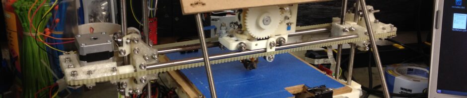
Back.. But now ANOTHER stepper board is fried??

Friday, May 21st, 2010

Agh!!

Ok well the good news is, my 16 day hiatus is over, and I can try addressing my stepper driver board problem.

The bad news is, one of the two replacement boards that I purchased to address the two bad stepper boards is now bad too! I’m afraid to touch the last one.

I was grounding myself the whole time, so I don’t believe it was a static problem. I used a 15-watt soldering iron. I had the board grasped by the corner of the board, in a vice, and made sure it didn’t come into contact with any of the components or circuit lines. The page describing the necessary modifications is here.

First (before any modifications, and before apparently breaking one) I tested both replacement boards (unmodified) by connecting them (one at a time) via ribbon cable to the Y-axis port on my motherboard, which was connected to the computer. I connected one of the makerbot.com Kysan stepper motors (with the clip still on it, so the motor wiring was right), to the stepper driver controller board. I connected the molex 4-pin power connector from a PC power supply to the stepper driver board.

I turned it on (this worked for each of the two boards), saw not only the green power light but bright red and green lights next to the stepper motor connections. Those bright red lights will be on even if all you have connected is power and the motherboard connection, the stepper motor cables don’t need to be connected.

Here’s a picture I took later of what it looks like when it works, on an unmodified stepper driver board.. The ribbon cable is going to the motherboard, and on the left I’m holding the red and blue wire (red=12V, blue=gnd) coming from an ATX power supply’s yellow and black cables (multitester says it’s the right polarity and it’s 12V):

When the stepper motor is connected on a board that lights up like this, it can be controlled via the RepRap host software on the XYZ panel. I got motion from both boards before modifying the first of the two replacement boards (which is now not working).

I only made ONE modification, then immediately tested it, and it was already dead (the green power light goes on, but none of the lights near the stepper motor connector go on, and if you connect a stepper motor you can’t control it via RepRap host – it’s completely unresponsive). The only change I made was removing the 4-pin molex connector and soldering on a two-way screw connector in its place. Here is a picture of the first of the two replacement boards, apparently broken (note the green power light in the bottom right and its reflection on the RJ45 jack, which is the only lit LED).

I’m extremely irritated/concerned/disheartened.. When I modified the original three boards, one of those worked and two didn’t. Now one of my replacement boards doesn’t work already.

Has anyone else had this happen to them?

I’m open to suggestions. I’m afraid to modify the other replacement board, lest I destroy that one too. I’m seriously confused because I was extremely careful – maybe even 15watts is too hot? (I made sure not to use my 35watt soldering iron). I’ve checked the board and there are no obvious shorts etc.

Aarrgghh!!!

Sunday Morning Status

Sunday, May 2nd, 2010

So close!!! So close, and yet, so far. I keep thinking “wow, am I actually almost done?” then I remember a whole host of things I need to do.

…but I am damned close..

So first off, right last week’s post I determined the cause of my recent motherboard problems – the cheap ATX power supply I’d bought from MakerBot in late October had died after 3 uses. I grabbed one out of an old PC, and everything was working again. I quickly recorded these three short youtube videos demonstrating at least some limited X, Y, and Z axis motion:

X-axis motion!

Y-axis motion!

Sickly almost Z-axis motion

While that was fun to do, and showed me that at least the hardware could move (and that I still have a problem with the Z-axis), that wasn’t the ultimate test of the electronics, because I’d only started doing the electronics modifications required for all of the circuit boards, and they’d have to be retested later. So, I dug into that task, and proceeded to make all of the circuit modifications necessary to all of the boards.

If you do something enough times, eventually you get good at it.

What a strange new skill I’ve aquired – removing RJ45 connectors from circuit boards. I’ll never use that skill again, but I’ve become pretty good at it.

Pulling out RJ45 pins

Again, I’ve found it helps to pull the still-soldered-in wires to the front of the plastic RJ45 enclosure (out of their slots), use pliers to break off the black plastic tabs holding it to the circuitboard, grab the RJ45 connector with the pliers and then bend up 45 degrees off the board (on the wires), then down, left/right, etc, then you can get it off first – and desolder the pins later.

Far tougher was the molex power connectors.. The whole bit in the instructions about melting one bit of solder, prying that part of the connector up a bit, letting the solder harden, then moving to the other side really did work.

Here are the three stepper driver boards, with everything removed.. (the one on the left already has its new 3-pin header for the opto-endstop connection, which I used for last week’s post).

So it turns out the 2-way screw connector I obtained for power for the stepper driver boards had 4 pins instead of 2. There’s no harm in that, it just means I have extra (live) pins hanging in front of the board. I decided not to order new ones and wait, but rather press on with these.

In my eagerness to solder something on, despite careful attention to other details, I can’t believe I actually soldered on this screw terminal backwards:

That meant that now once again I had to use that same melt-one-bit-of-solder-then-pry-that-side-up-and-let-the-solder-cool-to-add-tension-then-move-to-the-other-side trick that I’d just learned on something that I just soldered onto the board. Here is the fixed board with the screw terminals facing the right way (the blue silly-putty looking stuff behind it is called Blu-Tack, a silly-putty-like reusable “adhesive” that I’d never heard of before the RepRap project, which I found myself using to hold circuit parts in place before soldering them, which mostly worked well except the putty would get hot).

Here’s the final state of the modified stepper controller board. In the 3rd picture you can see the two live pins hanging over the end of the board, which I’m not too worried about.

The screw terminal I bought for power for the extruder controller board had 2 little plastic pegs on it that also were going to get into my way. I cut those off.

Here’s my modified extruder controller board. On this one basically I replaced the RJ45 jack with a screw terminal and a 2-pin header:

One of the toughest things for me to get off was the ATX power connector on the motherboard. I’d read that I needed to use forceps to reach in and pull out pins as I melted the solder on the other side of the board. The closest I could find to forceps one night while driving home was two different tiny tweezers. Neither could reach the pins well. Then I realized that I didn’t care about the ATX connector at all, so why not just butcher it with my dremel, cutting around the entire side all around, so I could expose the pins more. That worked out well.

Here was the resulting butchered plastic after I successfully removed all of the pins:

With all of the circuit board modifications complete, I mounted them all onto the two pieces of MDF that would hold them.

The bottom MDF also holds the power and USB connectors. I mounted those next.

I then mounted those boards onto the Mendel.

Unfortunately, I’ve now come to realize that it seems that two of my three stepper driver boards aren’t functioning properly. The three videos at the beginning of this post were all done with one stepper driver board being connected to one stepper motor after another. The other two boards won’t cause any motion in a stepper motor at all. Their green power LEDs come on, but that’s it.

That’s left me in a state of debugging. Here are some messy pictures, with wires everywhere, of what my Mendel currently looks like, with the boards mounted and cables running everywhere.

And on THAT note, I’m done with this post, and aside from any remaining RepRap work I may get done today, I’m probably done with progress for the next 16 days or so, as I’ll be otherwise occupied. So close! Certainly way closer than I thought I was a while back. Which statistically probably means I’m not as close as I think this time either. 😀 Either way, this is a fun ride!