Archive for July, 2010

15+ tries later, buying better stepper motor

Wednesday, July 28th, 2010

Since my last post I’ve done over 15 print attempts.. I fixed a bunch of things during that time, and felt I was making at least some progress, but I’ve realized that I simply won’t be able to print anything real with the Mercury stepper motor I’ve been using for my non-geared, standard Mendel extruder.

Today I ordered a high torque stepper motor with a 3/16″ round shaft (Lin Engineering 4218L-01-10) for around $10. I’ll cut splines into that shaft too (as I did with this one), and hopefully get enough torque that I can dig into plastic enough to get consistent extrusion so I can print a geared extruder (or, one thing at a time, print anything). 🙂

The new stepper motor is due to arrive Tuesday. I won’t be doing much until then.

All of that said, here are a few pics and video clips of some of my print attempts up to this point (after a few gratuitous 3D pictures of my Mendel):

NOTE: With the lazy-eye 3D pics, I’ve found it’s best to click on the pictures first, then try doing the 3D thing. WordPress tries scaling these to make them bigger, and in this case bigger is not better – it makes it very difficult to line up the images, and then there are scaling artifacts.. Click the pictures so they’re in their own un-scaled original forms first.

I love this first one – note the wires, the pool in the back, the table beneath it, the foremost threaded bar with the power cables on it, etc.

Look at this next one and see if anything looks “wrong”:

It took me looking at that above 3D image to realize that one of the M8 bolts on the top had almost come off from vibration. I had the actual Mendel right in front of me and didn’t notice it, but the 3D picture had me studying every bit of it and I noticed. 🙂

Here’s one last 3D pic:

Ok.. Here was video of JeffTry6, where I briefly got optimistic enough that I almost sound like that “double rainbow” guy (shiver):

Here was the result of that:

..and me talking about that:

So then I went about doing the math to determine what the number of steps/mm I should have for Z, and for that matter, for X and Y. I have McMaster pulleys (McMaster part# 57105K11) for my X, Y, and Z stepper motors, which have a larger diameter than the printed Mendel pulleys. For X and Y it’s easy:

// One step is the circumference of the pulley divided by the number of steps)
1 step = (McMasterPulleyDiameter * π)/ 400 mm
so
1 mm = 400 / (McMasterPulleyDiameter * π) steps

(where the 200 step (1.8Ëš) motors are in half-stepping mode, so we use 400)

That means my X_STEPS_PER_MM and Y_STEPS_PER_MM are 7.869315719200254 (I put 7.8693).

For Z there are two gear diameters and the leadscrew pitch to deal with too. For Z, my math was:

// 1.25mm pitch screw, 1 full turn, 1.25mmz
1.25 mm-of-Z-travel = (RepRapLeadscrewGearDiameter * π) mm-of-belt
so
1 mm-of-belt = 1.25 / (RepRapLeadscrewGearDiameter * π)  mm-of-Z-travel

Then combine that with the previous equation for 1 mm-of-belt from above:

// Same as above
1 mm-of-belt = 400 / (McMasterPulleyDiameter * π) steps
and you get
400 / (McMasterPulleyDiameter * π) steps = 1.25 / (RepRapLeadscrewGearDiameter * π)  mm-of-Z-travel

which reduces to:

1 mm-of-Z-travel = (RepRapLeadscrewGearDiameter / McMasterPulleyDiameter) * (400 / 1.25) steps

Maybe my measurements were wrong, or I’m taking the diameter of the wrong part of the gear.. My X/Y value seems ok, but my Z value didn’t work in practice. McMaster’s site says the diameter of that pulley is .637″ (16.1798mm). I measured the RepRapLeadscrewGear at around 1.125″ (28.5750mm). That gave me 565.1491 steps of the Z-axis motor to move the X axis up or down 1mm. So I set Z_STEPS_PER_MM to 565.1491 (in firmware, and also in the Preferences page), and it didn’t turn out right. It turns out the correct value through experimentation was 672. If someone wants to tell me where I got my math wrong on that one, I’m all ears (but again, it could just be the wrong measurement). And by the way, thanks to Laurie for verifying the math by solving the problem independently from me so we could compare our results.

Here’s how I determined the Z_STEPS_PER_MM through experimentation:

At some point after this I realized to my shock that when the nozzle moved towards the right on the X axis, the nozzle raised higher and higher above the bed. I’d previously spent time making sure this wasn’t the case, so I worried about how that had happened. The first thing I did was check the bed height with the spacer piece, and determined that the bed was correctly leveled. Then it hit me and I felt crazy for not having seen it immediately – the right leadscrew was somehow now a few turns higher than the left leadscrew. I think this happened when I’d been working to fix the Z axis problems I had a month or two ago. Anyway, I loosened the Z belt, adjusted it meticulously, tightened everything up again, and that’s all fixed now.

Then I proceeded to do more attempts at printing. JeffTry10 didn’t look very good at all..

Then another..

The best example of the fact that I’m not consistently extruding but rather dribbling with some slight push was this attempt at printing a 40mmx40mmx40mm cube, which I only let go for maybe 2 layers before aborting:

Before deciding to buy a new stepper motor with higher torque, I figured I’d give it one more try, this time changing the extruder firmware to use full steps instead of half steps, which I think should increase the torque. I certainly got more plastic out, but as you can see, it’s still not extruding correctly:

Here’s one more 3D picture of that print attempt, then a picture, then video:

That’s it for now. More next week!

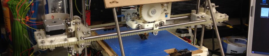
First (failed) Print!!! LOL!

Sunday, July 18th, 2010

IT’S PRINTING!!! Well, it’s failing spectacularly at printing, but it has extruded plastic all on its own while trying to make a mini-mug (a little shot glass that I can toast success with). Instead it’s a glob of plastic that only a RepRap parent could love. 🙂

There is video of that a few photos/videos down from here, but as usual I’ll show what led up to that first.

I’d only had two times last week that I could play with my RepRap and I was having problems getting it to fully extrude on its own. The stepper motor seemed very weak..

Here it was, thinking it was printing a mini-mug:

Here’s a video showing the extruder appearing extremely weak, unable to push out plastic.

Then I started getting much closer just by adjusting the motor mounting while it was trying to extrude, so I could see where it could grip. I still wasn’t there, but I was closer:

3-d cross-your-eyes picture of the plastic in the extruder (click for unscaled picture, which works better):

I’d posted to the reprap forum about my weak extruder problem and Wade said he’d had the same problem, and suggested cranking up the current on the stepper motor and slowing the extrusion speed. I had already tried turning the trimpot on the extruder board with no success, and remembered reading on the extruder controller page that the trimpot wasn’t currently used.

It turns out that it can be used by the FiveD firmware if you issue the right “M” command (M113). M113 without any arguments causes the trimpot to be read right then. I’d you supply an argument, though, you can specify a value right there in the gcode file.

That revelation led to one long uneventful video that I’ll spare you from, and then…. to THIS:

Here is my RepRap’s first printed attempt at making a minimug:

Here is the entire removed top bed with the failed print:

And here are two cross-eyed 3d pictures of that print (click for unscaled pictures which again work better):

When peeling it off of the bed it was interesting to see that the bottom layer that was really flat (I think I trimmed my z opto flag about 0.5mm too short) actually stuck together, despite the thrashing that the failed build did to the rest:

So now I think I just have to find the right combination of: a) the correct spacing between the stepper and the bearing, b) the right PWM setting to use, and c) the extruder speed. Not sure on how exactly to change c yet.. Changing the gcode directly probably affects the rest of the build – when I was using skeinforge on the Makerbot I had to change something pre-rendering. Eh, we’ll see.

BUT NOW, I’M PRINTING!!! Woohoo!!!!!!!!!!!!!!! Now to just get something to print correctly… 🙂

Extruding!! (by hand, but.. EXTRUDING!!!)

Monday, July 12th, 2010

SO much progress since the last time I’ve written about it.

..and I’m actually at the cusp of printing.. So close I can literally smell it.. but I’m in a whole different category of problems now – problems getting things to print, not problems building the machine! So that’s actually one reason I want to post now – to cover all of the progress up to now so I don’t have to do it later. And there’s a lot to cover.. Huge media bonanza in this post – enjoy.

Ok, where to start.. Well, in my last real post I gave a quick preview of two youtube videos, so I’ll include them here. The first one shows a strange (new, replacement) problem I was having with the leadscrews:

Here’s a video from a month ago talking about the wiring that I’d started. Wow that seems so long ago:

Here are some pictures I took while wiring back then:

Then I had weeks worth of round-the-clock work on work stuff, so I couldn’t touch my RepRap for just about a month. But then this week I was on vacation with my family, and snuck in some nights and a few daytime hours of RepRap work. In a previous post nuttzy had suggested that I bring the RepRap out into the pool with me – I did almost that, by bringing it upstairs to work on.

More pictures..

One of the apps I have on my iPhone is a small app that makes it easy to take 3D pictures – you take a left and a right shot, line them up, and it’ll make either a parallel or crosseyed version for you (although sometimes it seems like it’s mixing those up, so I go with whatever works best). Here were two of those that I couldn’t resist taking.. It works great on an iPhone, not so good on a big screen TV. You want it to be small enough that you can cross your eyes and make the two images overlap then click, then the 3D effect takes place and you can easily make out depth. The downside to the first one is the fact that the front-most part is out of focus, which kills the whole 3D effect if you try to focus on it (which is a downside in any 3D pictures/movies).

I can’t get WordPress to not scale these images to be bigger, and scaling ruins the effect, so I’ll provide links to them.

3D-image-1

3D-image-2

The next thing I did was scratch an itch that had been driving me crazy ever since I got the Z-axis installed – I made feet for my Mendel. I also cut out the removable top MDF sheet to place on top of the bed, so that after a print I can just remove that and take the pieces off without reaching around inside the Mendel.

Another thing that had been bothering me was my power connection. Ultimately I’ll get around to obtaining a 12V power brick and connect that to an XLR connector for power, but I’ve been busy for the past month or so, so for now I have an ATX power supply. I’d been connecting two wires from the ATX power supply into the chocolate block on the bottom, but got sick of that, and figured what the hell – I’ll buy a 2nd XLR connector for when I eventually get an old laptop 12V brick, and free the current one up for me to wire it for use with the ATX power supply. However I didn’t want to wed myself to any particular power supply, since they often die, so I needed a molex connector.

I couldn’t bear to cut one off of any of the countless computers/accessories in my house, and I actually started looking at mouser.com for raw parts. Crazy. Instead, Y-adapters for 4-pin molex power connectors are like a buck. I had one in the other room, but again thought of the many times I use it. I went online, bought 3 more at around a buck a piece (they’ll arrive later in the week), and that freed me up to butcher that cable. Here’s the very nice result.

By the way, I LOVE the feel of an XLR connector – the locking feature is nice, and it’s just a very satisfying click. They’re more prevalent in Europe, from what I hear (at least for power) – I’ve never seen one used for power here in the US.

Next, I had the X-axis built up again to the point where it was moving (after having mostly fixed my Z-axis problems, and temporarily disabling my X-axis in the process). As for the details on this next video, I don’t think I was actually using the home feature at this point. I probably moved X, Y, and Z to some non-zero coordinate, then told them all to go to 0. I don’t think that at that point my Y opto flag was working, and Z didn’t even finish during the video, but I was still happy about it:

Next, on to the extruder. I decided to use a purchased 5mm nozzle, but make my own Mendel-sized barrel. In fact, I made it 4mm shorter so that the total length of the barrel and nozzle combined would be the same as the standard Mendel barrel. There was less space for the nichrome heater, but that’s good – I want to keep that heating zone short anyway.

Here I show why I’m building an entirely new heater barrel even though it was one of the first things I’d completed, and showing the old and new one side by side:

So I used that new barrel, purchased nozzle, and purchased PTFE insulator to build the heater assembly. I wrapped nichrome wire around it, wrapped that in Kapton tape, attached my thermistor, wrapped that in Kapton tape, and taped up the wires. Then I took it upstairs to test the thermistor:

I’ve noticed that since I’m so close to being done, the idea of printing SOON has raised the stakes of everything I do. So quite often I’m filming video before doing something, realizing that that might be the video filmed before a moment of tragedy or triumph. Here was one such pre-event video, about the simple task of cutting notches in my purchased PTFE insulator (I’ve made at least 9 on my own, but during my last makerbot.com purchase I threw in one so I’d have a perfectly centered, professionally machined one in a pinch).

And the follow-up result video:

(No, I still don’t have a lathe).

So now I was all ready for another task I’ve been dreading – gluing my PTFE insulator into my Mendel extruder piece. I’ve been dreading that because with the Makerbot I went through at least 5 or 6 PTFE insulators, and this one will be permanently welded to my pristine Mendel extruder piece (which I can’t print any more of, not having a working printer).

As with many of these worry-about-it tasks, there wasn’t much to worry about (at least until the PTFE insulator dies someday, but hopefully that will be after I print out a better extruder piece).

My JB-Weld experience:

JB Weld works by mixing two agents. The first is this black goop:

then you mix it with this (which I put right on top of it in this pic):

Here’s what it’s like when you mix it:

Here was the result before drying:

The next day:

So then, getting really close, I hit a huge roadblock. While others get to use new cool geared extruders like Wade’s Geared Nema17 Extruder or Adrian’s, I’m stuck with the RP parts I have, and that means I’m using the standard Mendel Extruder piece for now (at least until I can print a new one). That means the extruder shaft needs to directly push the plastic against a bearing, and a bare smooth extruder shaft won’t do anything but slip. I’d previously purchased this S10T08M012A0505 small gear wheel to put on the shaft, as suggested under “Adding a small gear wheel” here.

As soon as I went to put it on, though, I realized it wouldn’t fit inside the Mendel Extruder part:

Ignoring that problem for a while, I continued on with tasks I still had to tackle. I built a small stripboard with two 4-way connectors, as was suggested in the RepRap Wiring video – one set of four is for the extruder stepper motor, and the other is for the heater and thermistor connections. I built an 8-way ribbon cable with two 4-way connectors to mate with that. Here’s it all put together:

Then I got the final Z opto flag remade in tin and working great (somewhere before this I’d remade the X and Y opto flags in tin as well). The original Coke-can ones I’d made were just too flimsy – a slight breeze would knock them out of alignment. These new ones were made from a tin can of mandarin oranges (thanks Emily!). I also had to replace the X opto endstop board with a spare I’d made, because it stopped working for some reason (I’m using polarized connectors, so it wasn’t the polarity).

Finally I wanted to see my extruder actually extrude (which I originally envisioned I’d do waaaaay before assembling any of the Mendel itself!). I rested the extruder on the top of the frame, hooked it up, and did the test (pushing plastic in by hand). Despite what the first video says, I went with 170 degrees C (who knows what temperature it really was – I haven’t done any thermistor calibration or anything). I was using UltiMachine 4042D PLA.
Two part video:

Ok, so that left one remaining problem.. Getting the extruder motor to be able to grip the plastic to push it in by itself. Not being able to use the gear wheel, I decided I’d try cutting splines in the shaft, as described under the “Getting your stepper to put splines on its own shaft” section of the Pinch Wheel Variations page.

I built this rig to do the trick (from the above instructions):

Then here I describe and use the rig:

Did I mention I was close? 🙂

Laurie and I were up pretty late, as I told her I was so close that I needed help bringing stuff upstairs.. I brought the RepRap, and she brought the lazy susan with PLA on it. 🙂 As I untied the twist ties around the PLA, I remembered when I’d tied the PLA up previously – it was when I had to return the Makerbot; that was a sad moment, this was happy. We set our expectations low (rightly so), hoping just to have it extrude. We then had the X-axis start to fail (aaaggghh!!!), but Laurie figured it out (she’s a genius!). 🙂

And there ya go.. That’s all I have. I started typing this up Saturday night, ended up typing it through Sunday night. Actual prints probably not coming until next weekend sometime.

(and congratulations to anyone reading this far.. Did you actually watch all of those videos?)

Thanks go to Tom Royer for the continued use of his corded Dremel (vs my cordless one), and to Reed P. for his Dremel extension (which I’m returning tomorrow as I now have my own). While I’m at it, thanks to P. Newman at work for helping me with various mechanical issues that I couldn’t figure out (like how to remove a stubborn set screw which was driving me crazy, among other things). Thanks to Chris for giving me someone to talk to in person that’s reading as many of the online reprap blogs as me (your parts are coming soon I hope!). Thanks to Laurie, Emily, Alicia, Cara, and David for giving me a day or two of our vacation to do this latest push, and for being the best support in the world.

Oh, and again, thanks to you for reading this far. Seriously, who made it this far? 🙂