So much to cover. A lot has happened in the past month (aside from my virtual tangents). And I REALLY should break this up into multiple posts, but I can’t – so it’s going to be a huge long post of LOTS of pictures and video (yes, I say that all the time). Let’s get to it.
Printing again
One shipment of gears later, and I’m printing again.
I took the opportunity to do a few things, each of which had benefits and consequences:
1) I finally corrected my mistake and set up the bolts in Wade’s Extruder correctly. (I bought 4 M4 bolts with hex heads (70mm long I think) at Lowes – it was nice being able to go to a local hardware store and find metric anything.. There’s nothing metric at Home Depot that I’ve seen (at least not near my house). That did make it much easier to mount (no worrying about trapped nuts falling out, because there are no trapped nuts – those holes are for hex bolt heads).


Ok, that one didn’t have many consequences. I’d just been putting it off.
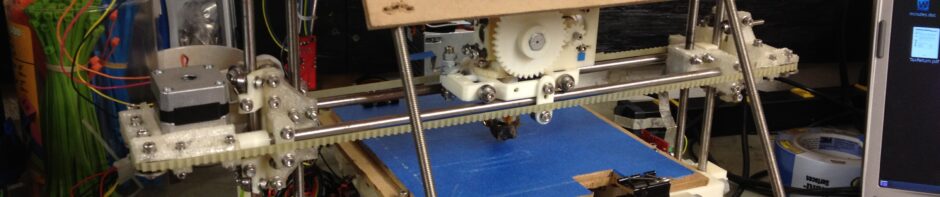
2) I mounted my Wade’s Extruder sideways with Tony Buser’s sideways mount piece.
When I ordered some gears from Tony, I also ordered a print of his sideways mount for Wade’s extruder. I’d expected this but he sent me two versions; the version I used was this:

I’m not sure exactly where this particular object is on thingiverse, if it is at all. It looks a lot like this part of thing:4307 but it’s different enough that that’s not it. I haven’t gotten around to asking Tony where the model is for this. Hey Tony, upload this version, it works great! 🙂
The immediate benefit is more build height. When printing the bag holder that I use to take the trash out to the curb, I wasn’t able to print all of it because my extruder’s stepper motor would hit the top of the frame. With Wade’s Extruder rotated 90 degrees, the X axis can raise much higher.

The new build on the left was able to print to its full height.
The second huge benefit is now you can mount and unmount Wade’s extruder without having to disassemble the whole thing. The idler bracket can stay exactly where it is.
The third benefit was that the heater barrel is now centered in my X carriage. This had been a concern for me before, as it was previously off-center, with the heater barrel right up against my easily-meltable PLA x-carriage.
And the fourth benefit is that the bolt hole in front of the large gear has a recessed area for the head of the bolt, so it’s well out of the way of the large gear. Previously, taking the large gear off of Wade’s Extruder meant straining everything to bend back the extruder to pull the gear out. Now, it comes right out.
Ok, but issues arose. First, to get my PTFE insulator through the hole, I had to remove it from my Wade’s extruder (because of the wires for the heater and thermistor). Then, some of the kapton tape fell off (I’m looking forward to someday leaving kapton tape behind), and the thermistor floated free in the air instead of being held against the nozzle. I agree with what I read someone say a week or so ago – kapton tape is not a real solution for holding thermistors against barrels. (or maybe my roll of kapton tape is just getting old – it doesn’t seem to stick like it used to).
So I had to at least slightly rewrap. But I had to do that anyway, for a different reason. Tony’s mount is at least 6-7mm tall if I remember, and with the short heater barrel I was using, that made my heater barrel not go down as far as the bolts on the bottom of my X axis.


It also meant that the inside of my X carrriage was exposed to more heater barrel. That’s one of the reasons I wanted to rotate the extruder in the first place – concern for heat in my x carriage.
I dreaded having to make another (longer) heater barrel right now. I just made one recently, and it was the one I made on my own without any external nozzle (the original Mendel heater barrel design). Plus, I’ve wanted to keep the heat zone on my heater barrel very short, so I don’t use longer purchasable heater barrels (even though I have some lying around). Plus, that wouldn’t solve the heat-in-my-x-carriage issue.
So instead I realized the solution was to make a longer PTFE insulator. That would lower the heater barrel, and insulate the carriage from heat. I’ve made several, but they’ve all been a pain. This is another area where a lathe would be nice. I couldn’t do my spin-the-piece-in-my-drill-press trick because the 16mm PTFE was too wide for the chuck of my drill press (I did wonder if people sell some sort of chuck extender to fit into an existing chuck and provide a much wider one.. but then I realized they probably don’t, because really that’s all the stuff of lathes). So instead I just drilled it, it wasn’t centered perfectly, but it worked. I decided to make it 13 mm longer, so I made it 48mm long. 3mm hole all the way through, then I think I used a 5mm bit on the other side (15 mm deep) before tapping it M6.
The next issue I ran into (that might have been a problem I already had?) was that with 3 washers, the large gear had at least one time on its full rotation where it’d push up against the small gear too close and catch/hang. Spacing it out with an extra washer fixed that, but moved the knurled part of the screw even further away from center (but again, it extrudes and prints, so..)
Battling with my X-axis: Part 1 (The Problem)
So now that I was printing again, and that I’d tested printing that taller bag handle above, I printed a test “K” block. Despite my attempts to ignore my x-axis problem for the short term, this was un-ignorable. Look how horribly all-over-the-place this block is in along the X-axis (left to right):

The Y axis is fine – looking at that from the side shows the edges line up. But looking at that from the front, you can see that layers go left and right from where they should be. As it turns out, this was caused by one of two overlapping problems I had with the X-axis – but I didn’t know this yet.
I had several theories about what might be wrong with my X-axis. One theory – the one that I started working on first, was that there might be some drag on the X-axis from the filament supply I had resting horizontally on a lazy susan behind the RepRap.
I’d used this lazy susan with the Makerbot successfully before, but I think the reason it worked in that case was because the Makerbot’s extruder doesn’t move – it just stays in the same location. As a result, the only issue for the Makerbot was whether it grabbed enough plastic. On Mendel, however, the carriage moves left and right, so extra drag on the filament might cause problems with the carriage moving. Plus, there’s a horrible coiling affect that happens when plastic comes off of the top of the spool, converting from its horizontal resting position to a vertical pull into the extruder:

Battling with my X-axis: Part 2 (Attempt to Test a Theory)
Upon describing this to my Dad during a long drive to a football game (Go Pats!), he asked if there was a way to remove the extruder and instead mount something that could hold a pen. That way, the filament-drag idea could be tested, by removing filament from the equation.
I immediately replied that yes there was, and that I’d planned to download and print a pen holder one day, but probably after I had everything working. Still, I figured it was worth a try. So I downloaded the Mendel Pen Holder, put the parts in an RFO file, and tried printing all three parts at once. (That was a knowingly foolish move, but it turns out to have yielded a good example of my X-axis problems.

It didn’t turn out well. Here you can see the three parts. Because I forgot to set the print order of the parts correctly, the back part printed first, then the part on the right, then finally the part on the left. As you can see in these pictures, my X-axis was accumulating error as it progressed within each layer, such that the third object printed was in a far different location than where it should be.

Specifically, look at the tall portion of the third part printed (on the left). It seems shifted way to the left of the base of the piece. What’s actually happening is that the base was shifted way to the right of where it should be (because of all of the error accumulated during the lower layers, from printing out the other pieces). The carriage was drifting more and more to the right of where it should be. But once the Z-axis had raised enough that the other two parts were complete, you see the higher portions of that piece were now printing where they were supposed to be (but since the parts below it were to the right, the top appears to drag left).


This was actually an illustration of my second overlapping problem with the X-axis, but again, I didn’t really know for sure yet that there were two problems.
I believe I made one more attempt to print that tall piece on its own, but I then put on hold the pen mount until later, instead deciding I’d just plow ahead with one of the solutions I’d already planned. (McMaster parts arriving in the mail helped that decision along, as you’ll see).
Battling with my X-axis: Part 3 (The Filament Spool/Spindle)
I’d determined that even if it wasn’t the cause of my X-axis problems, I wanted to build a vertically mounted filament spindle (or filament spool – both terms are out there), to reduce any drag whatsoever on the X-axis.
I looked at the existing spools on thingiverse and finally settled on a combination of three things:
1) Simple spool system for a Mendel (or other 3d printer) by camiel
I didn’t actually print any parts from this entry – I just followed instructions on it.
2) Simple spool system for a Mendel (or other 3d printer) by brokentoaster
This was a modified spool bearing, where you put the 608 bearings in the spinning part itself. I also studied the pictures in that thing to figure out how I wanted to mount it, including printing out 8 y-bar-clamp_10off pieces and buying the appropriate bars/nuts/bolts/etc.
3) Extensions for simple spool system for a Mendel (or other 3d printer) by Gavilan
These extensions bolt onto the 3 support bars, to keep the filament from spilling over the left or right side of the spool.
What I ended up with was uuuuuuuggggggggggggggggggggglllllllllyyyyyyyyyyyyyyyyyyyy, but it worked, and solved one of my X-axis problems.


(And actually those above weren’t that bad.. what was ugly, was to come). I realized that my X-axis problems would affect this piece, but I figured I’d print it, and if it was even SLIGHTLY usable I’d make it work (however I needed to), and if it solved my X-axis problems, I could print a better quality one later). Here’s the ugly:


This picture actually makes me feel dizzy looking at it, like I’m seeing double, but I’m not:

More ugly:


And if you don’t feel drunk yet, three more:


Then I printed out the extensions.


In this one, you can see the drastic difference that having the Z-axis optoendstop correct has; the piece on the left had the nozzle home just a paper’s thickness over the bed – the others were printed previously, when the endflag was too low (causing the nozzle to start too high).

Undeterred by the fact that there was no way a 608 bearing would smoothly fit into that, I bought a nice set of forstner bits and drilled out an appropriately sized hole. I put in the bearings, used a hot glue gun to make it fit nice (and fill in some of the holes in the plastic), and eventually ended up with this:


Then I put filament on it, and mounted the extension pieces.

And then, I mounted it on my Mendel!


Brace yourself: extremely exciting video ahead:
Then I tried printing another K block. Here was the glorious result of that print (ignore the brown spots):

Note the smooth lined-up edge on the left
The filament spindle had indeed fixed the first of my two overlapping problems with the X-axis.
Did you hear my foolish optimism thinking that that might have solved everything? 🙂


Ok so once I came down off that high (double rainbow, all the way!), I cautiously tried printing what had failed spectacularly for me before – a large Wade’s Extruder gear. In this next picture, the new print is on the bottom left, the previous attempt from the summer is above it, and an ABS gear printed by someone else (not sure if that was the one from Neil that broke or a new one from Tony) is on the right.

I’d actually let myself think that maybe the filament drag (fixed by the spool) just miiiight have actually been the entire problem. Nope. So this was the first time that I definitively knew that I’d had (at least) two different overlapping problems with the X-axis, and that I’d only solved one of them.
Battling with my X-axis: Part 4 (The Belt and Pulley)
So I moved onto other theories that I’d had. The belt could be too loose, maybe I hadn’t filed the shaft down on the X-axis stepper and the pulley was slipping, and here was a big one – maybe the McMaster pulley (a 10-toothed pulley) required microstepping to get adequate resolution (vs the 8-toothed printed pulley that’s supposed to be standard).
Worse theories hovered in the air like a storm cloud – maybe my X-axis bars were corroded/dirty enough that they were causing problems, or perhaps the plastic had shifted and now the X-axis bars weren’t parallel. Maybe the bearings in my X-carriage were gunked up, and it was just broken. Replacing the X-axis would be a major pain in the ass – I’d have to take off the Z belt, I think I’d have to take off the bed, etc. No fun.
Here’s a video from earlier when I was printing that pen mount.. Once I saw that it was making mistakes with layers, I filmed about a minute or so of the underside of the X-motor-bracket, where the pulley goes through this torturous path around bearings and the pulley. Note that the pulley was the McMaster pulley I purchased last April, which again has 10 teeth:
The belt certainly looked suspicious.. Maybe loose. Just barely hanging on to those turns. Plus, again, there’s the potential resolution problem that a larger pulley could be contributing.. One full turn moves 10 teeth instead of 8, and the number of steps for the motor stays constant, so there’s at least some less precision with this pulley than with a printed one I have lying around waiting to be installed.
So I decided to start down the road of replacing that, and that meant removing the X-belt from my Mendel. That was something I’d wanted to avoid if possible, since it meant changing a key variable in the equation (the tension of that belt), and who knew how much worse that might make things. Worse, if I removed the belt and the carriage still didn’t move smoothly, several of those worst-case scenarios might suddenly emerge as likely.
I dove in and removed the X-belt.
Beautiful. Very smooth. So that left the pulley, motor, and belt tension.
I removed the X stepper motor and took off the McMaster pulley. Sure enough, I’d been lazy and hadn’t filed down the stepper motor, but if I remember correctly I think the set screw had dug in pretty firmly even on the round shaft. So the first thing I did is file the shaft. When I was filing, I wasn’t sure which way nophead’s pulley (sent to me by Neil Underwood with my Wade’s Extruder) needed to go on, so I filed two parts (rather than filing the whole thing).


It turns out, it needs to go with the fat part on the outside:

You can see why here:

I put the pulley on, and tightened the belt much tighter than it had been (but still not so tight that nothing moved).
I recompiled the firmware to change X_STEPS_PER_MM to be the default setting for the 8-toothed pulley, uploaded it, and printed a calibration object. It came out beautiful.


That was good to make sure I had the new settings right for the new pulley, but it didn’t test the real problem. The best test for that would be the Wade’s Extruder gear, since that had always failed spectacularly.
So I printed that.


So good! It might be just a tad shy of usable because it might be slightly oval (because I still can tighten up the calibration from the last calibration object I printed), but that might be just being overly cautious. But anyway, that’s not the point. The point is – that solved my second overlapping X-axis problem!!!
Need more pictures of the successful gear.. Here it is compared to the most recent failure:

And here it is next to the functional one made out of ABS. Again, the color/transparency issue is because the gear I printed was printed with PLA (which is clear), vs ABS which is opaque and beige colored.


Horray! So I then remembered that I’d wanted to print out two Pinchwheel Worm Drill Jigs in case I needed them in the future – so with my new functioning printer I printed two out:

They came out great. Then even though my X-axis problem was solved, I went to address one of the last items on my list – I figured I’d at least try printing an alternate X-motor bracket that eases the path for the X-belt. I started a build, and headed up for bed. Luckily once I got to bed I pulled out my iPhone and looked at the streaming video of my RepRap and I saw it failing miserably. The barrel had apparently hit the bed and had pushed out of the barrel. For some reason the motor was stuck near the dump location on the bed. Anyway, fail:

A week went by and I rebuilt things, then tried printing (using the new (working) debian package for RepRap Host and firmware), and eventually had it crash and push out AGAIN (in fairness, I was trying to re-use the longer PTFE insulator I’d made). I did witness one issue though.
With the new software, I’d let it specify all new default settings for Preferences (except ones I specifically wanted to set). I noticed that after a layer, Z sounded different.. it didn’t accelerate and decelerate when moving up – it just made a little “beeeeeeep” like sound (presumably moving faster at a constant speed). But later after the crash, I found that it was in a state where even when I used the jog controls to move Z up 10mm, it failed to do so, and instead just made the same beeeeeep sound from the stepper. I forget exactly what I did to reset it, but I think it was strictly jog controls, and then it started responding normally.
I’m planning on trying that new gcode with the old 0806 firmware to see if Z makes the same new sound – I’m thinking it’s just new faster default settings that I can dial back down to speeds that I work OK with.
I did one more thing before finishing this post (I’ve been trying to post this for a while now). I finally took the laptop power supply I’d purchased and soldered on the XLR connector I bought for it – to replace the ATX power supply I’m using.


So there ya go! There’s my progress for the past month or so. Did anyone actually read this far? 😀
Pingback: clip art gambling slots
Pingback: liberty university dissertation
Pingback: dissertation completion pathway
Pingback: demystifying dissertation writing pdf
Pingback: thesis vs dissertation
Pingback: help-seeking dissertation
Pingback: doctoral dissertation writing help me
Pingback: Printing again, reclaimed my vertical space, and X-axis woes/triumph!