It’s been a LONG time since a blog post, and this isn’t much of a post. Just wanted to say that I’ve migrated from my old hosting provider to a new one, so hopefully everything is intact. The theme is different.. I may chose another one and change it up yet again. That is all.
(Note: This post is being posted out of order.. the blog is still technically behind to 2013, but I’m jumping forward to February of 2014 for this post. Today is February 3rd 16th, 2015. Yeah…)
During February of 2014, I printed something on my 3D printer every single day.
Way back in 2010 I remember reading about people printing something every single day of February. The result of several Google searches yields the site thing-a-day (thing-a-day.com redirects there). I now more clearly remember that people were tagging things with thing-a-day on thingiverse, so this wasn’t just a tradition of printing things, but designing and uploading them.
Whatever – these days it’s tough enough for me to find time to PRINT things every single day for whole month, so that’s what I did. (Some days I even snuck in more than one print)
Here’s my diary of what I printed on each day of February 2014. I recommend trying at least this version of the (new) tradition if that’s all you can do, although maybe next year I’ll try designing something new every day (but I doubt I’ll have the time for that – I could barely do this!). I dub this print-instead-of-design tradition FFo3DP (February Full of 3D Prints). #FFo3DP
(It’s a pity that you can’t tag ‘makes’ on thingiverse or I’d tag all of mine #FFo3DP when I eventually upload them).
(Note: this is a very, very long post, with an insane amount of pictures. You might want to just let it load all of the images first, then come back and read. 🙂 )
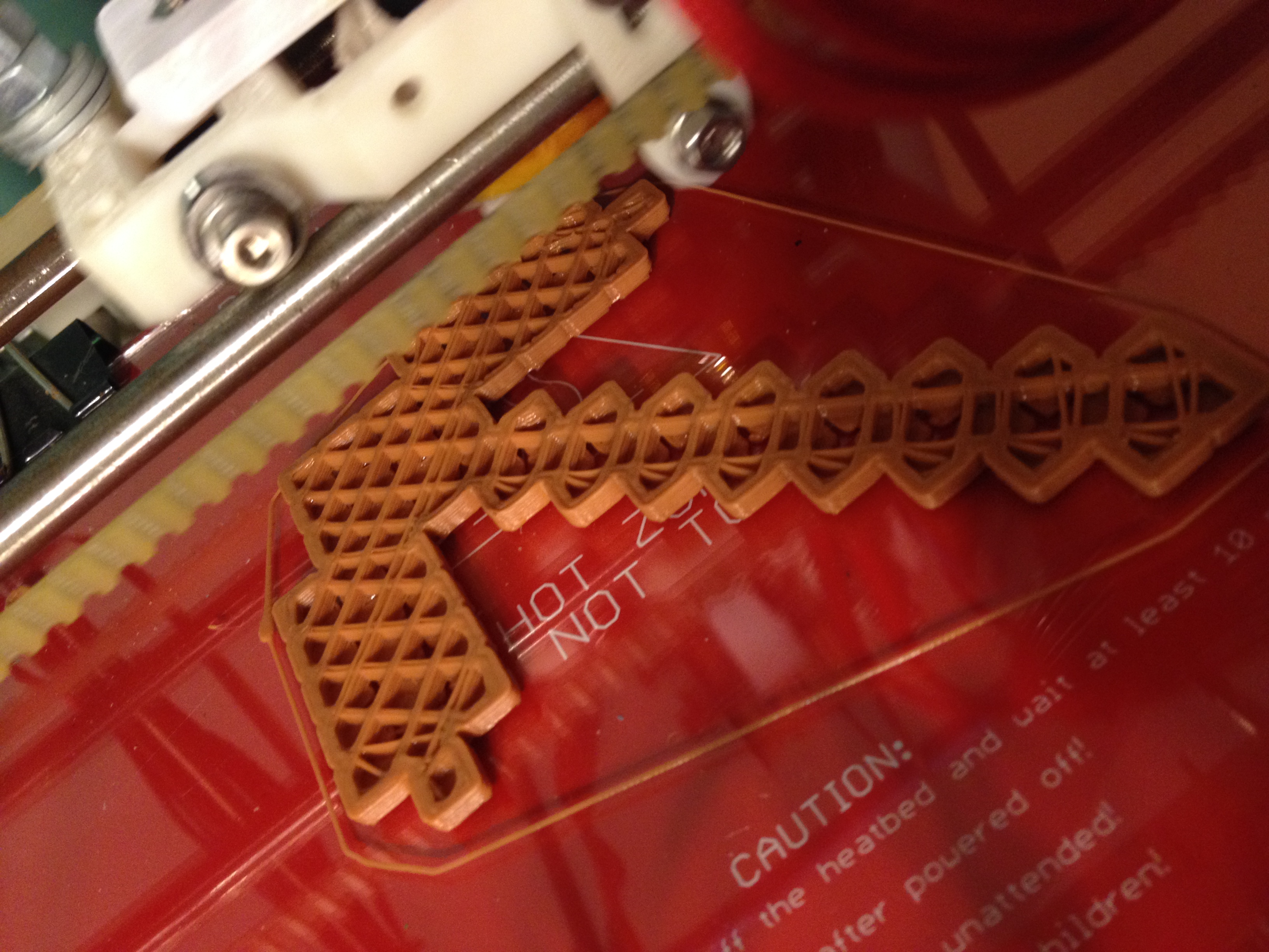
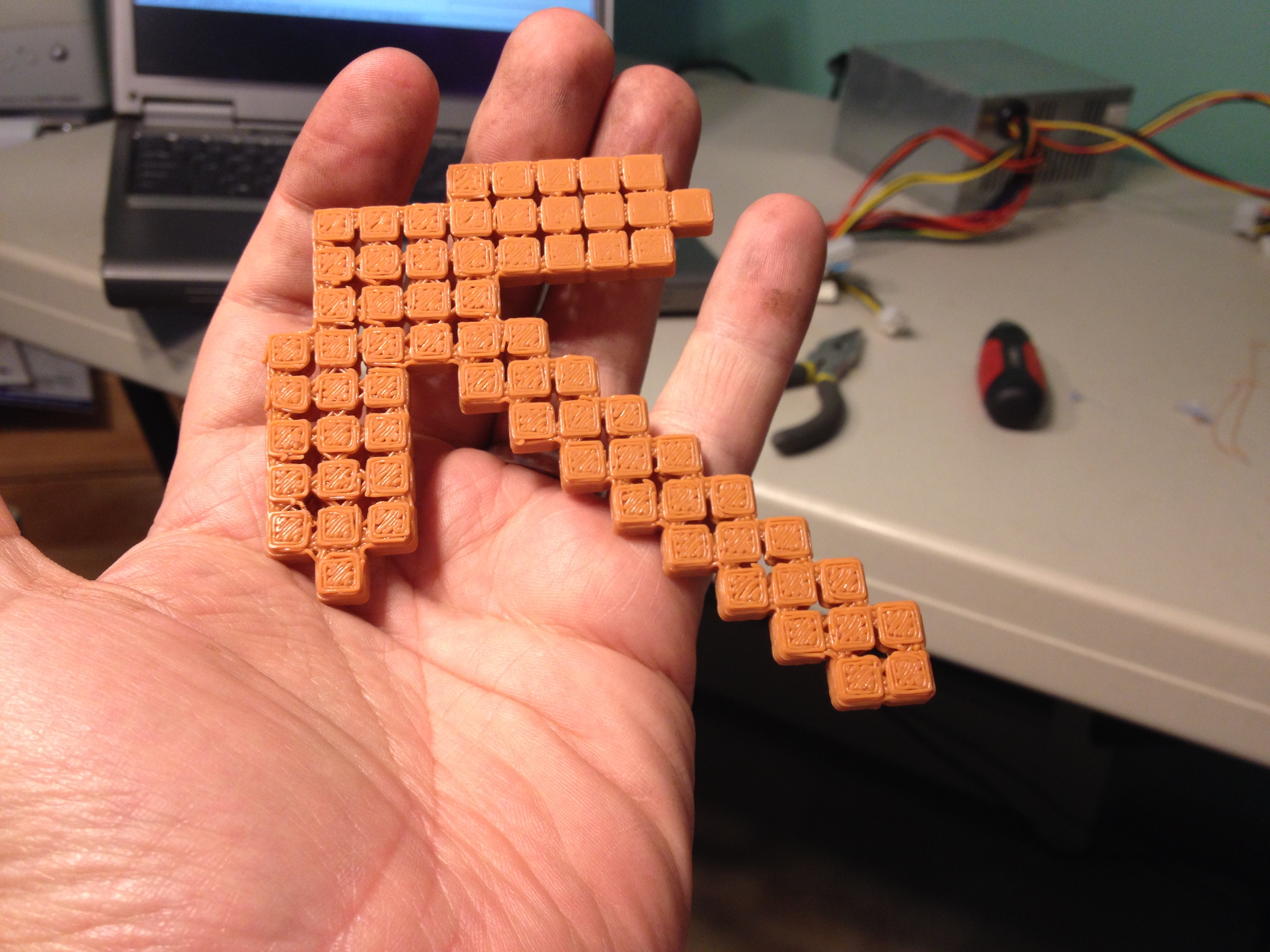
Minecraft Pickaxe, Mini Apple II, PL1Q Vampire Arm – February 1, 2014
First I made another Minecraft Pickaxe (I’d made a poor quality one at home before, and an incredible one at Makerfaire NY 2013 which I gave to a sad kid, and another poor quality one at home, so I needed a good one).
Initially thinking I might have “extras” piled up for if I had days I couldn’t print, I printed more than one thing that day. I soon realized that would be cheating, and that I needed to force myself to print something each and every day (one day I even waited until after midnight so it was the next day before printing something). 🙂
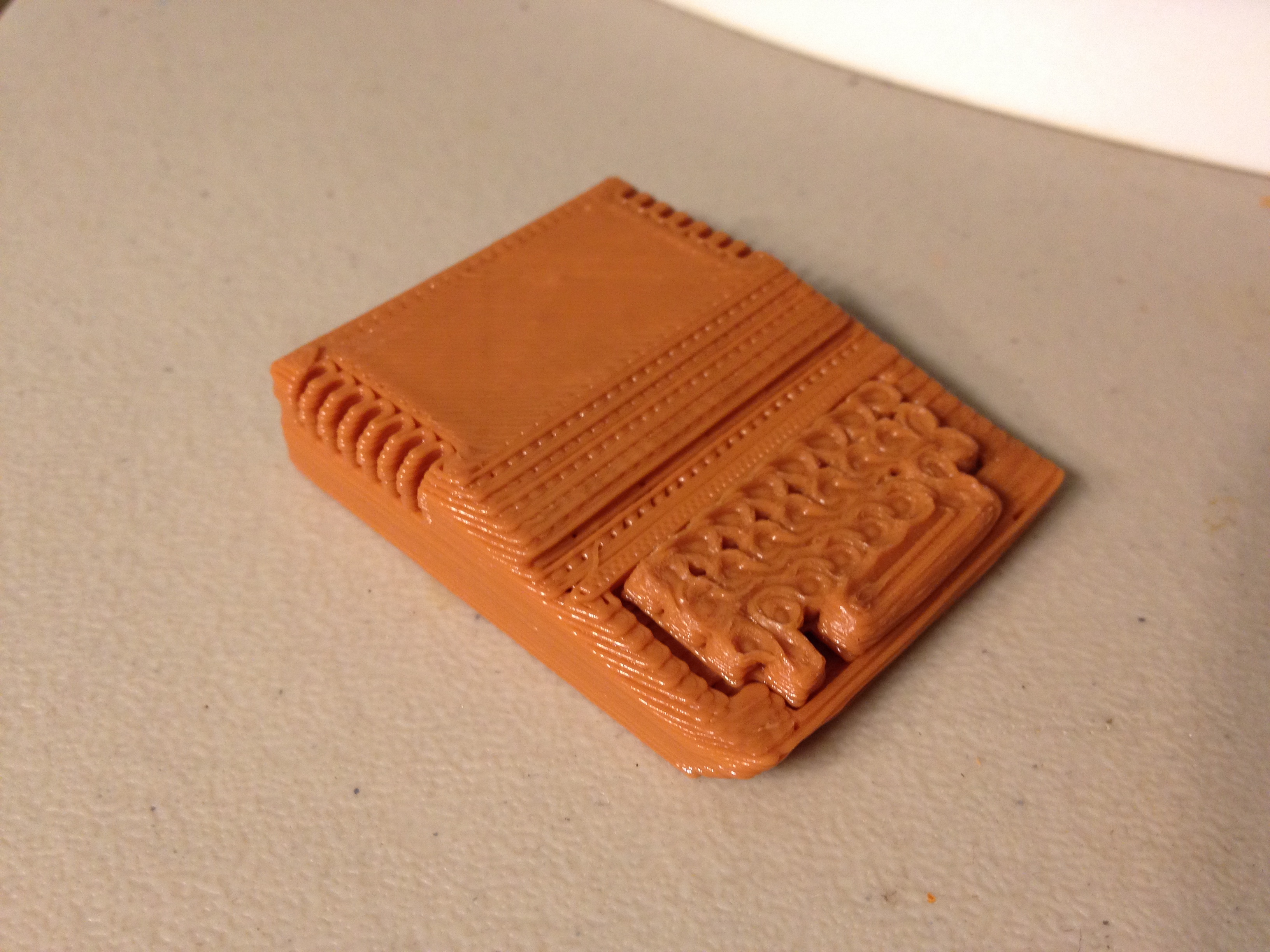
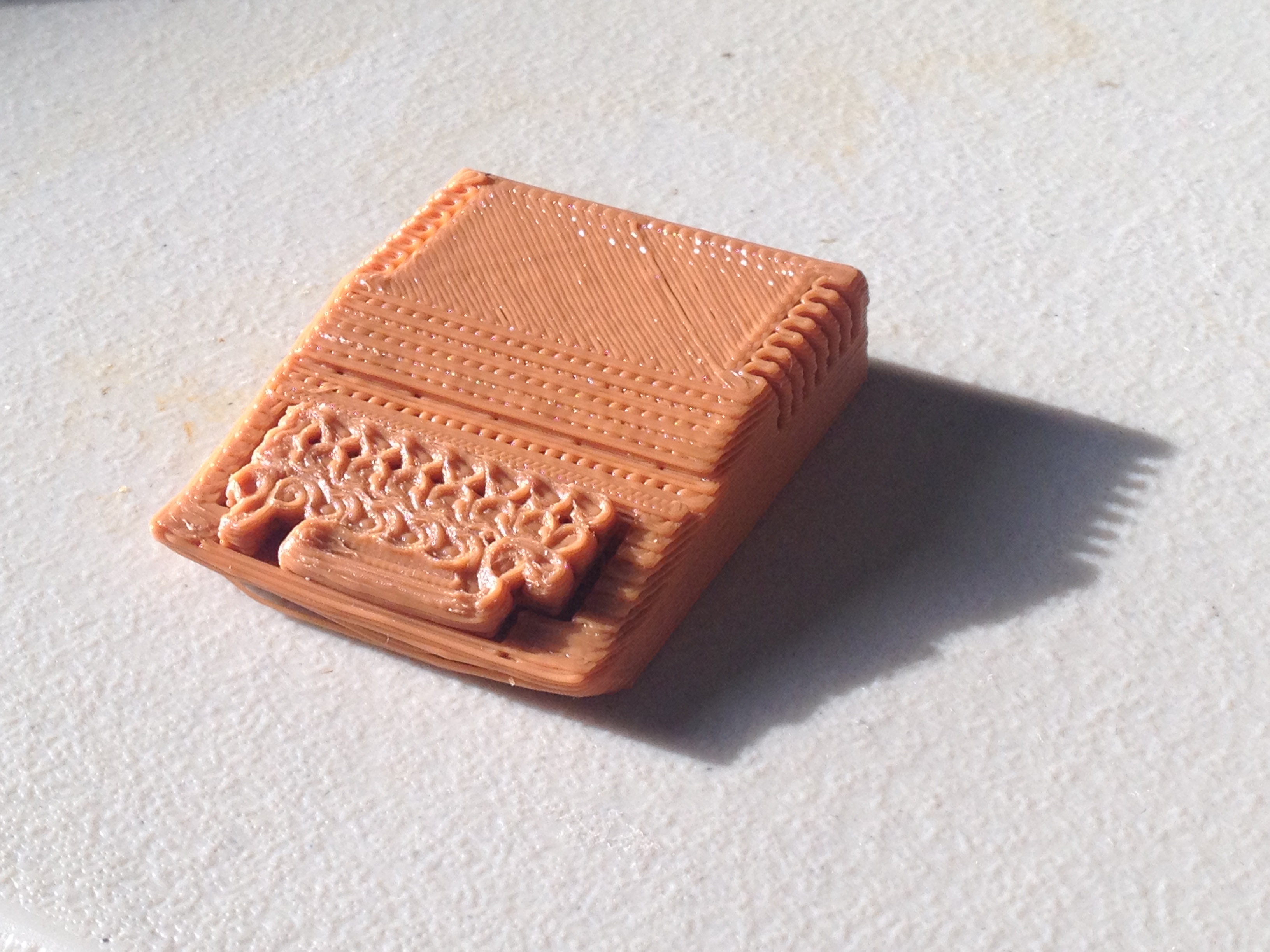
So I also printed this Mini Apple II model, which prints as two pieces (the case and the keyboard).. this was my 3rd computer ever:
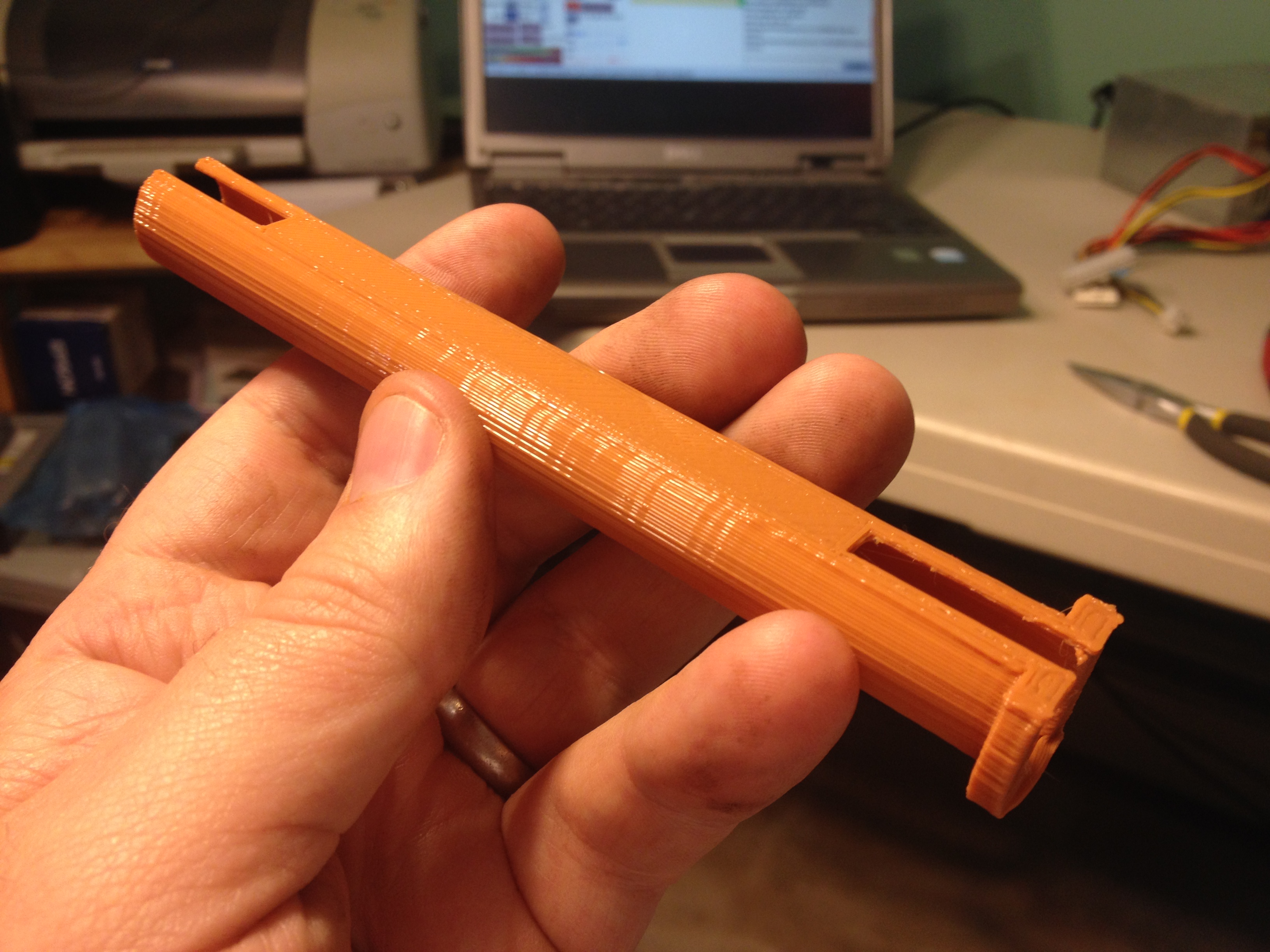
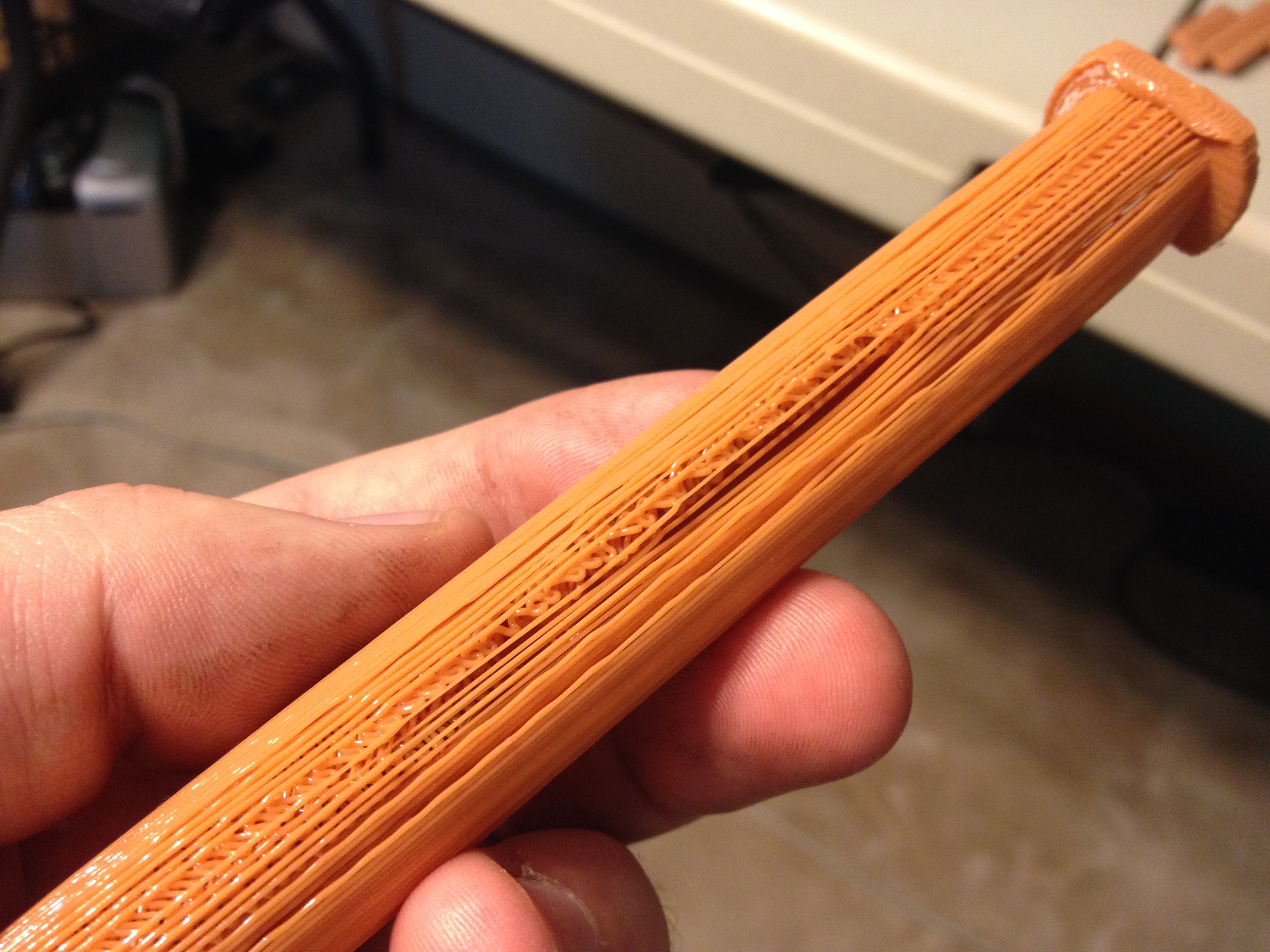
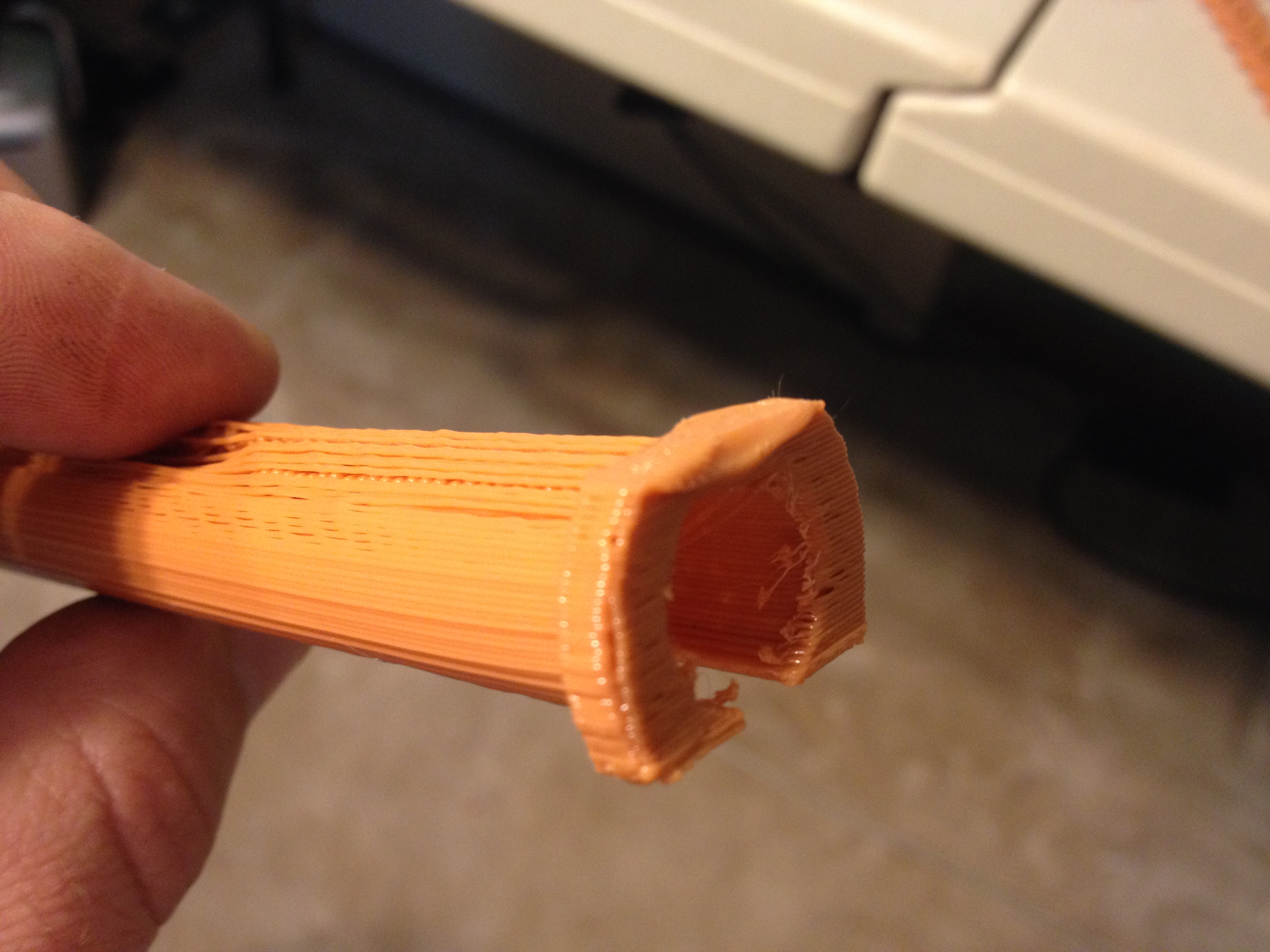
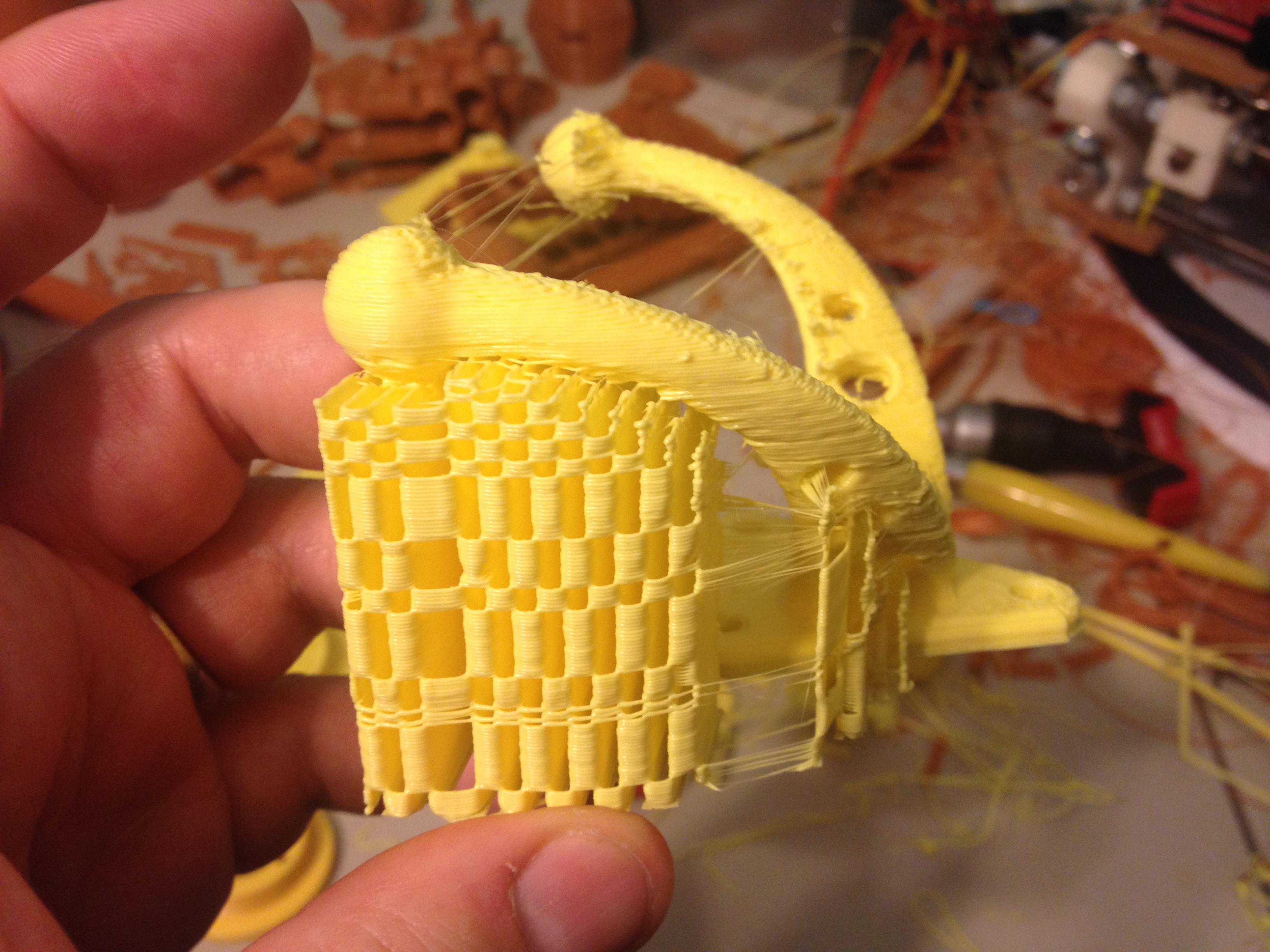
I also tried printing out an extra arm for my quadcopter in a different color (which I could use for the “front”), but it didn’t turn out well because of a gap on the top..
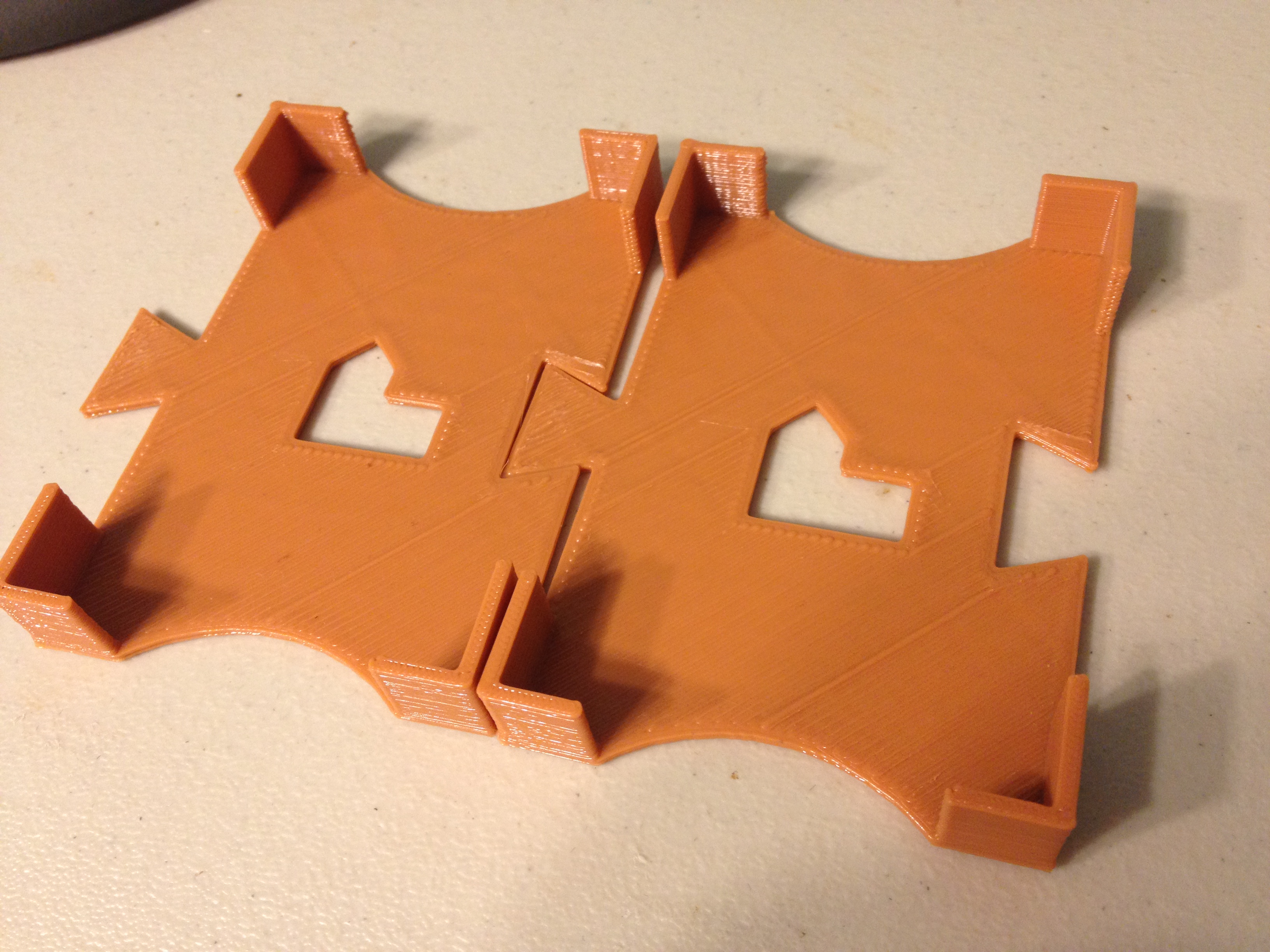
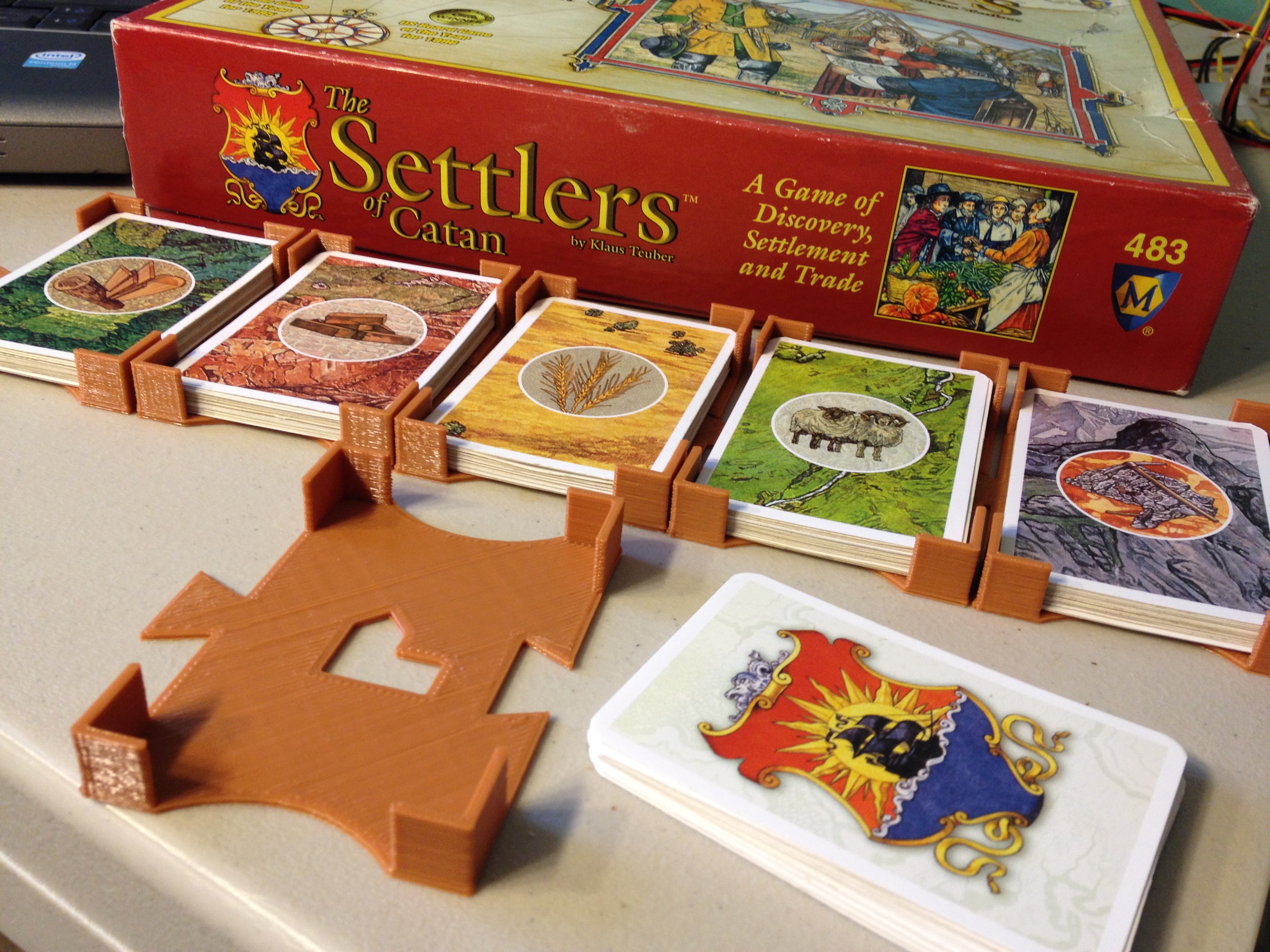
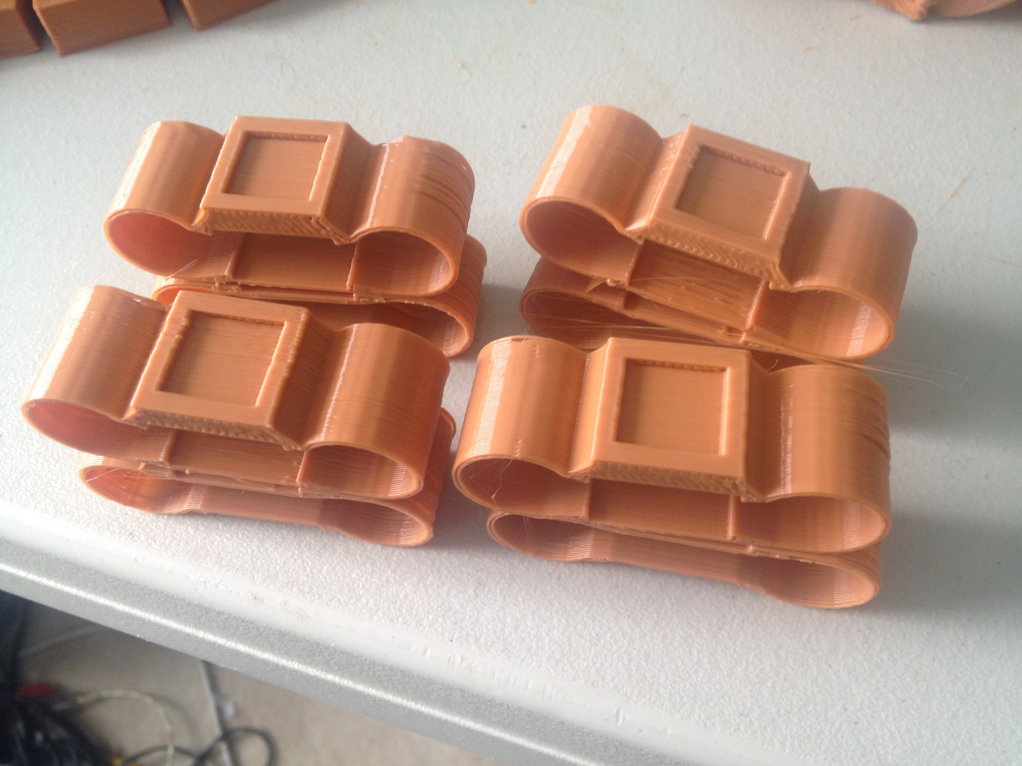
Game Card Holder, Catan Piece Holder, Arduino Uno + Breadboard Mount – February 2, 2014
I printed six of the Catan Game Card Holders, to hold the cards used by the “banker”:
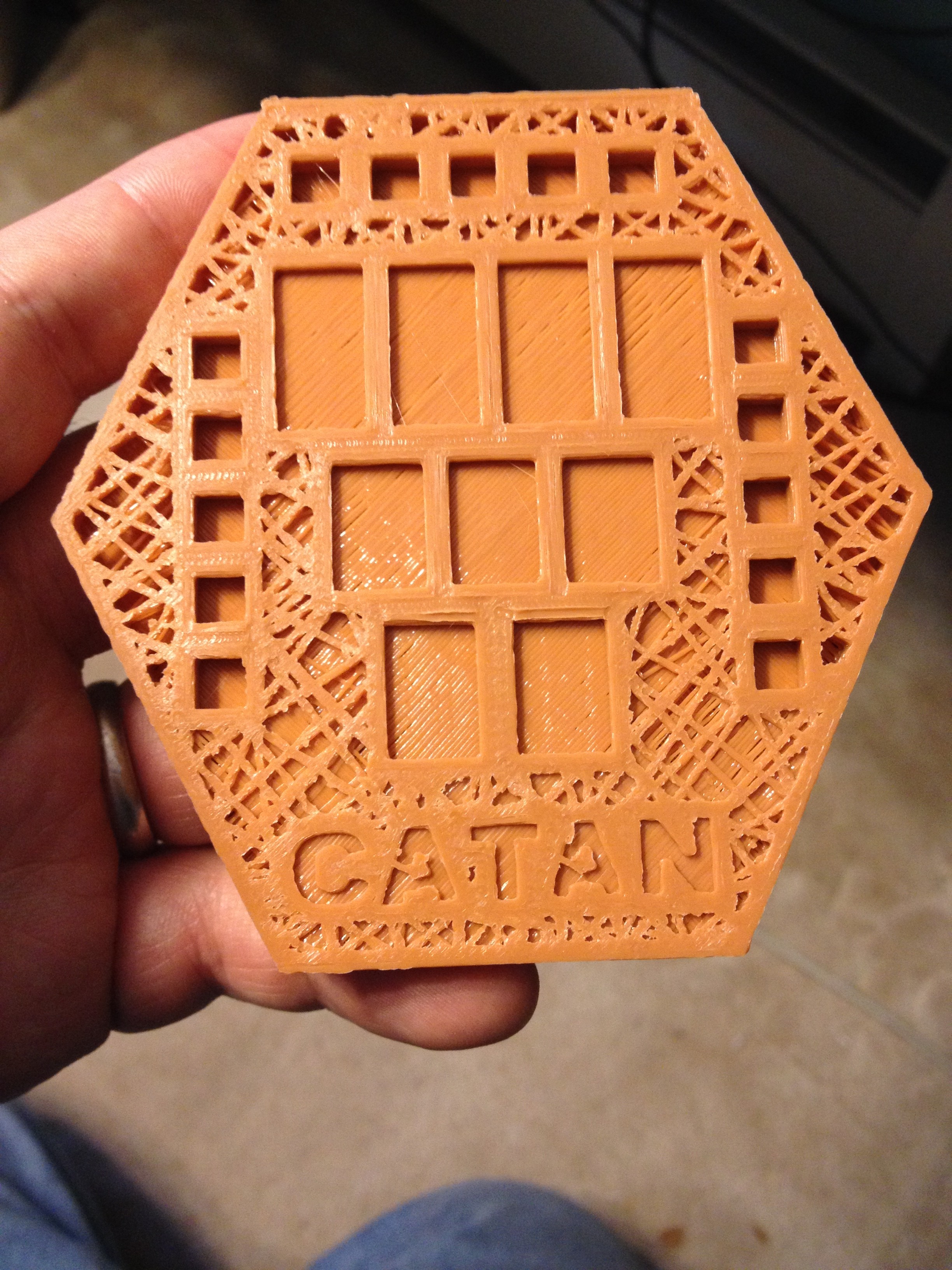
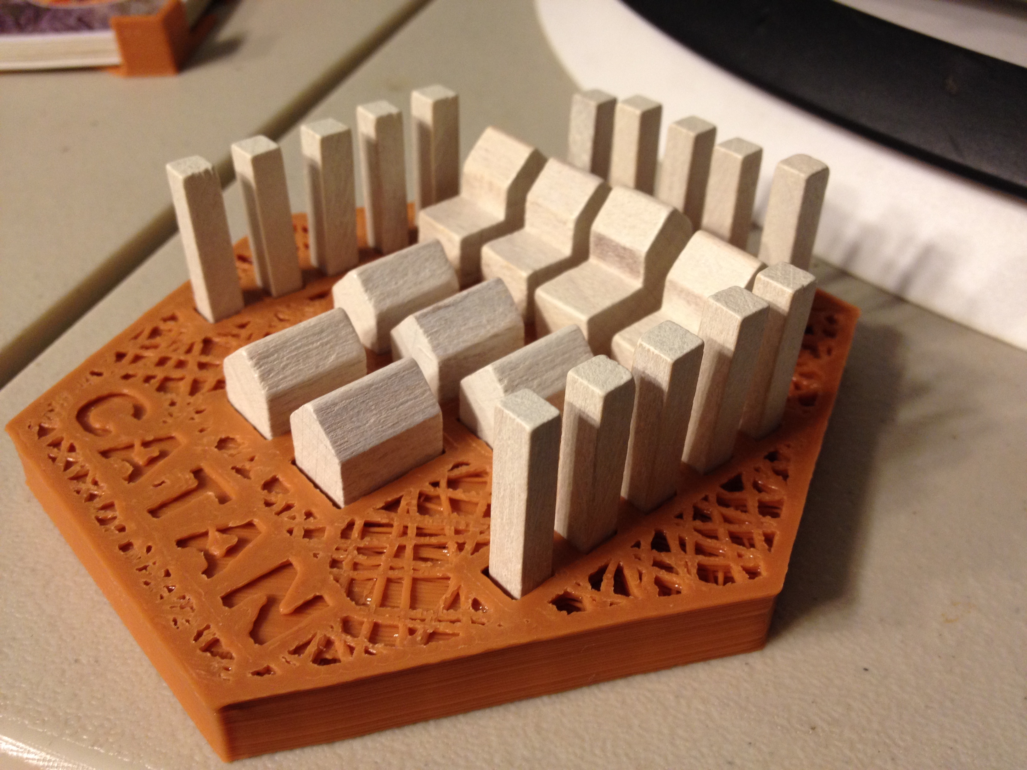
I also tried printing this Catan Piece Holder, which failed mid-way because of a jam but was still far enough along that it was technically usable:
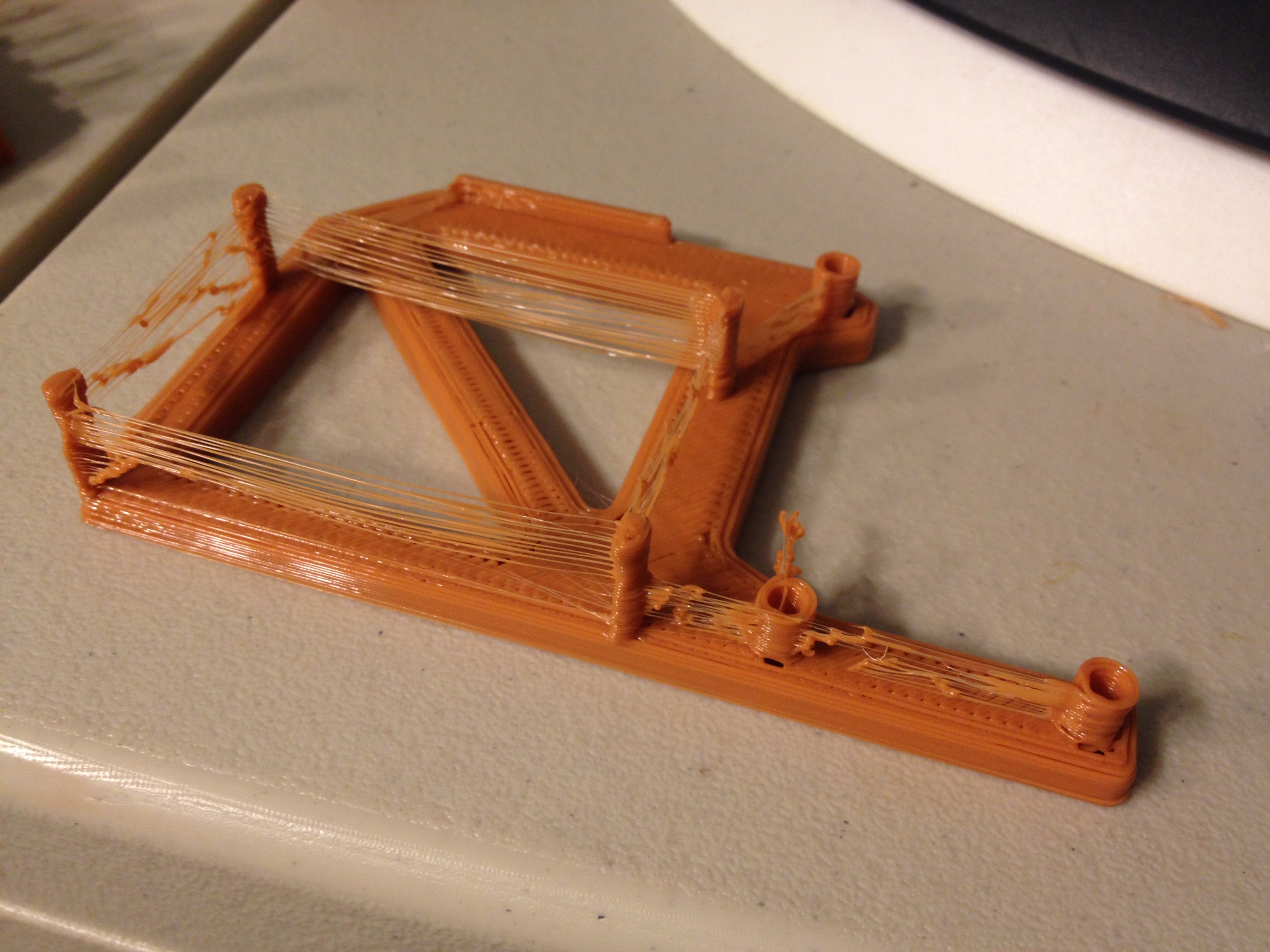
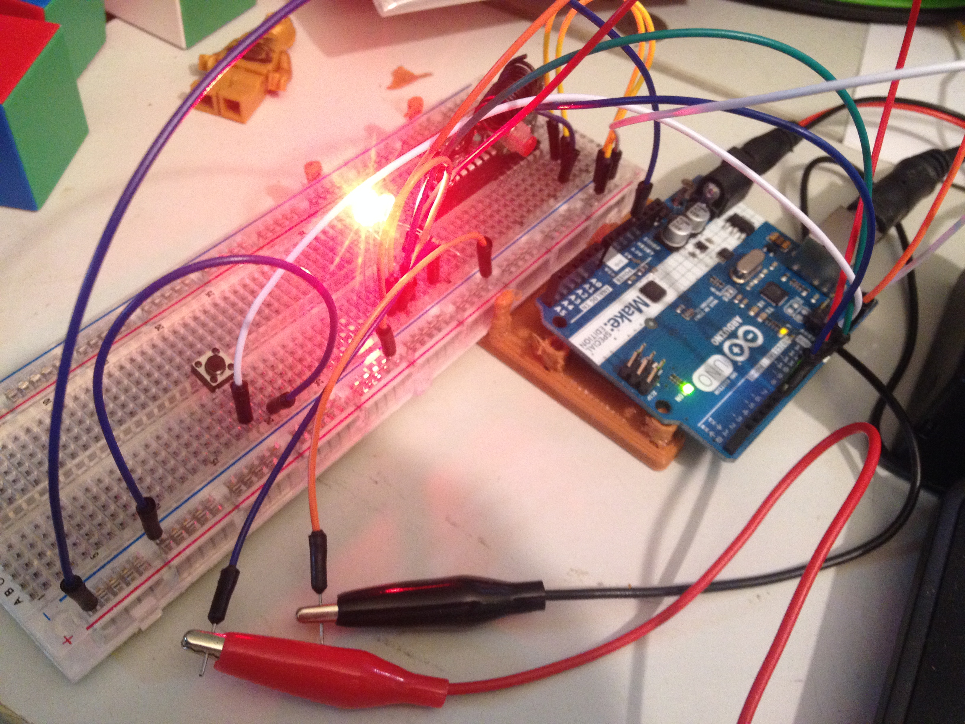
After resetting the printer I tried one more print for the day, an Arduino Uno + Breadboard Mount to hold my kids’ Arduino Uno to their breadboard:
Here is the Arduino and breadboard mounted on it:
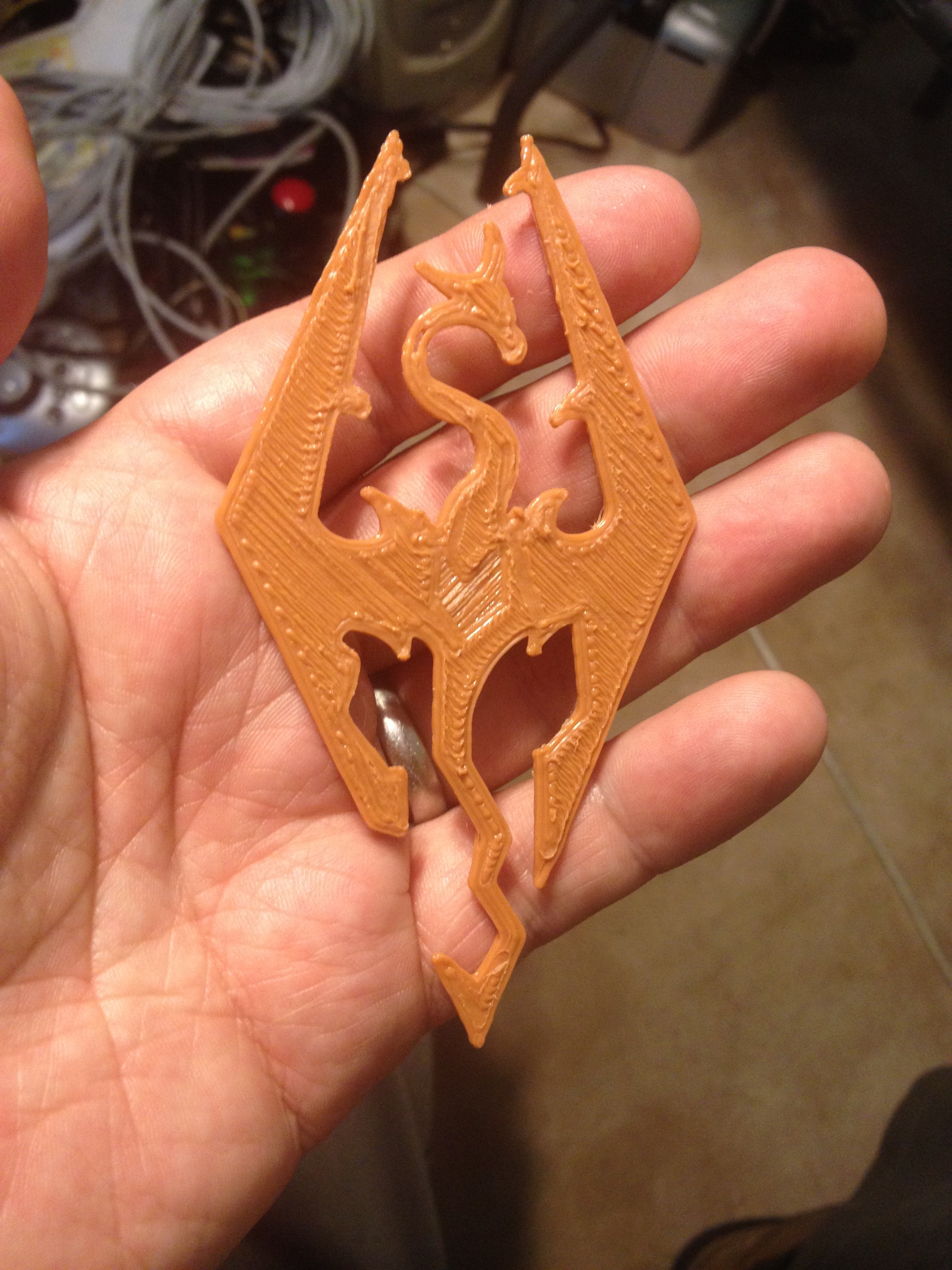
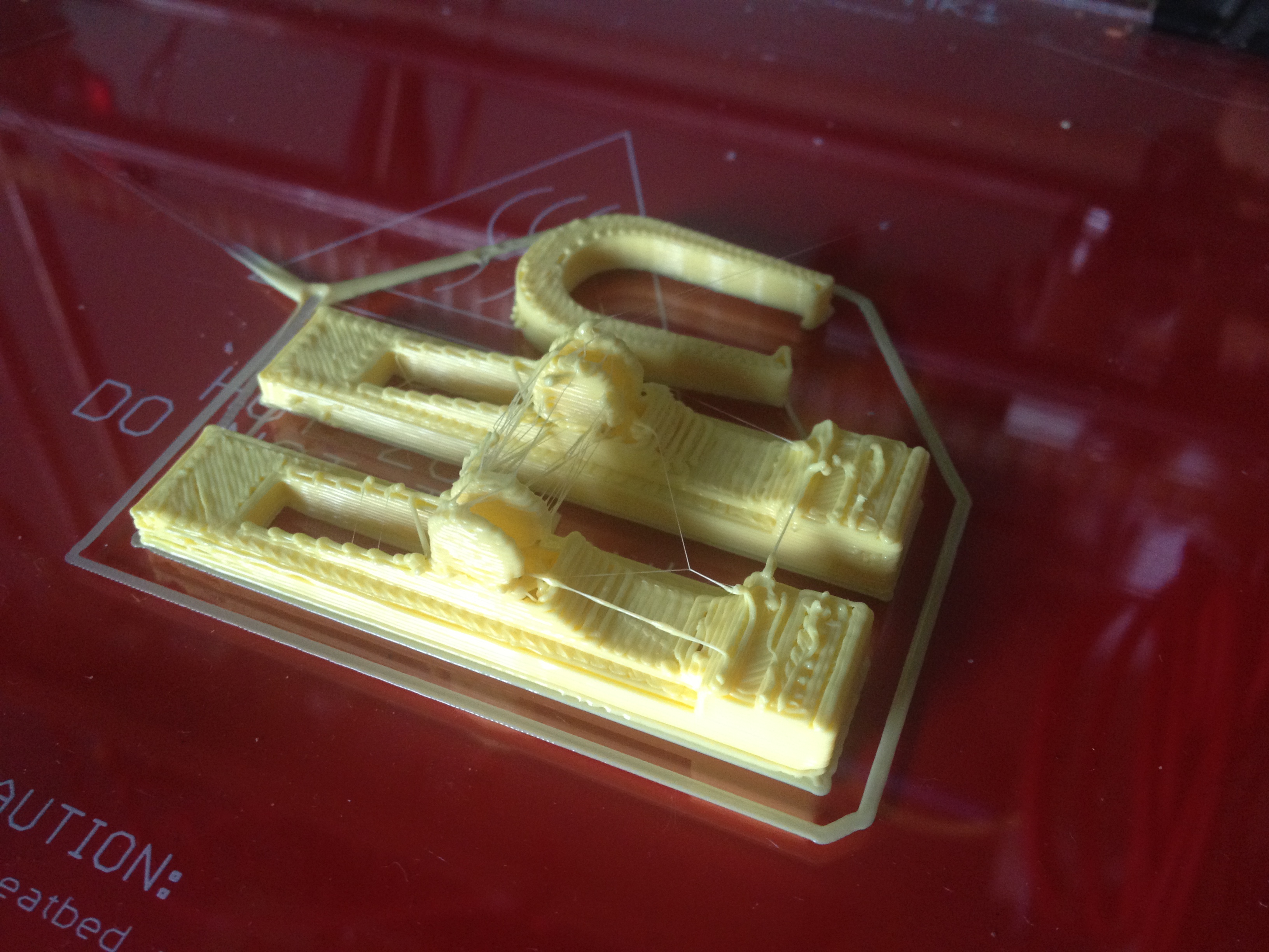
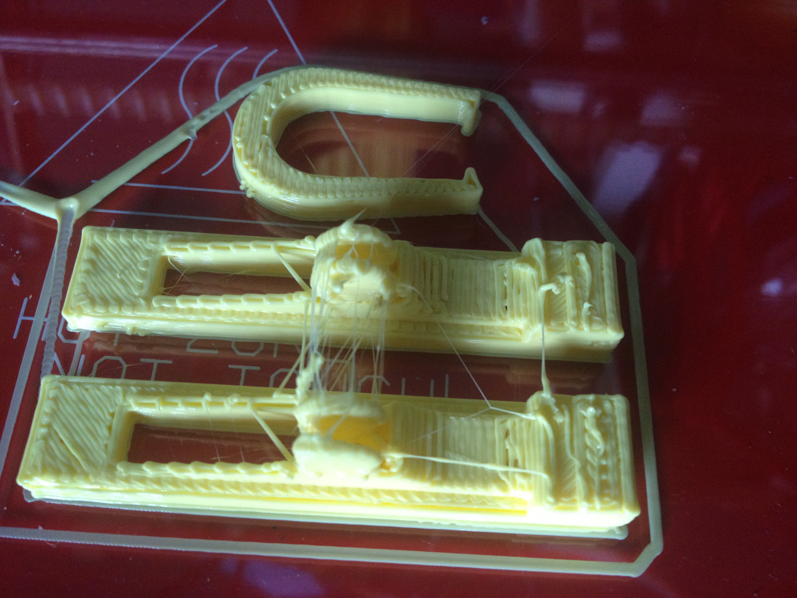
Skyrim Logo (Flat) – February 3, 2014
I rushed home so that I could print something before midnight. This Skyrim Logo was flat and quick, so I managed to get it printed in time.
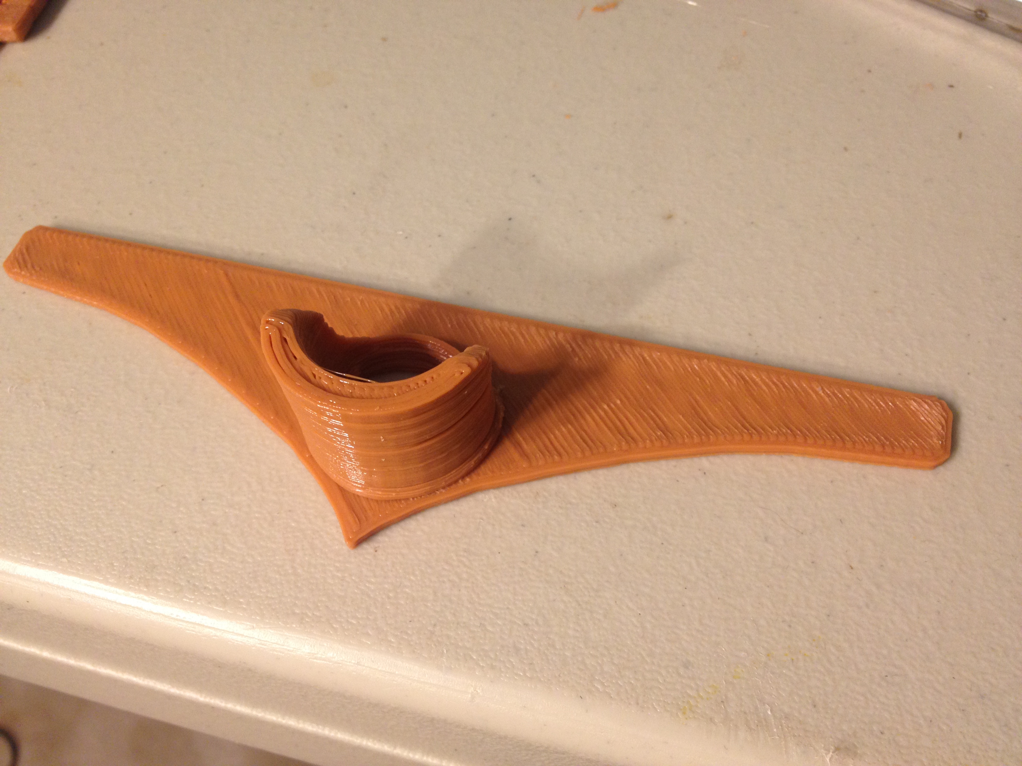
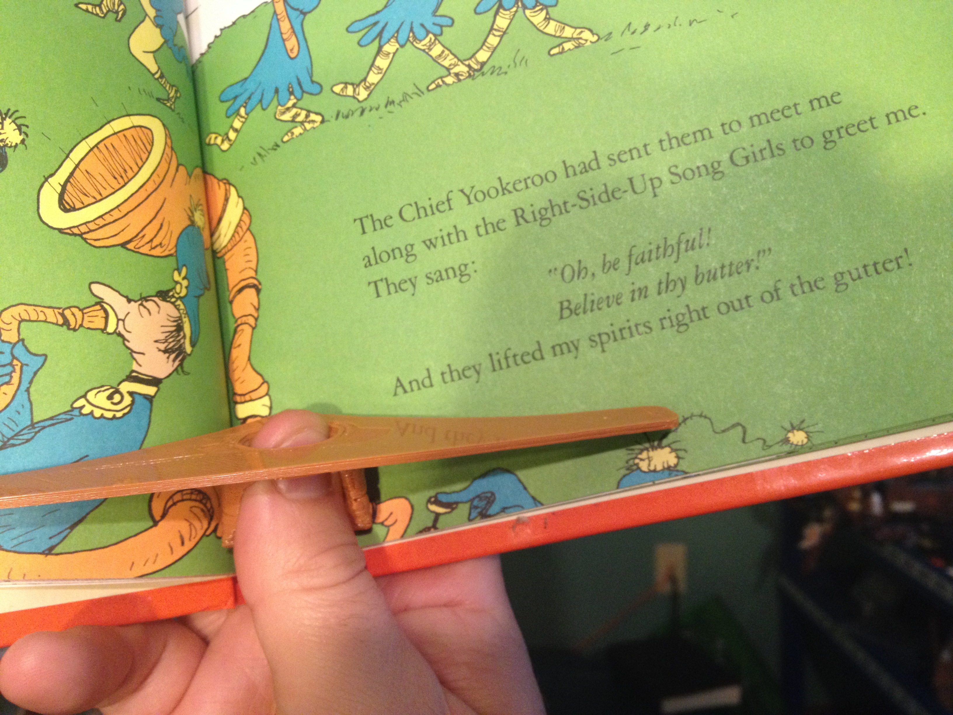
Page Opener – February 4, 2014
After seeing a post from Amy Buser about wanting Tony to print her this wooden book-holder-opener device that fits on your thumb, I posted that someone had already designed that for them (I’d just seen Book Ring, Advanced Page Holder Opener on thingiverse a few days earlier), and added that to my list. When I went to print it though (actually on February 3rd), the scale was wrong (I had to scale it up by 25.4 to get it to millimeters), and I was running out of time, so I went with the Skyrim logo above instead. Between then and today though, a memory was nagging at me and I searched and found that Vik had created a similar device over four years earlier, Page Opener, so I went with that instead.
(I may try the other one, and a third one too, someday later).
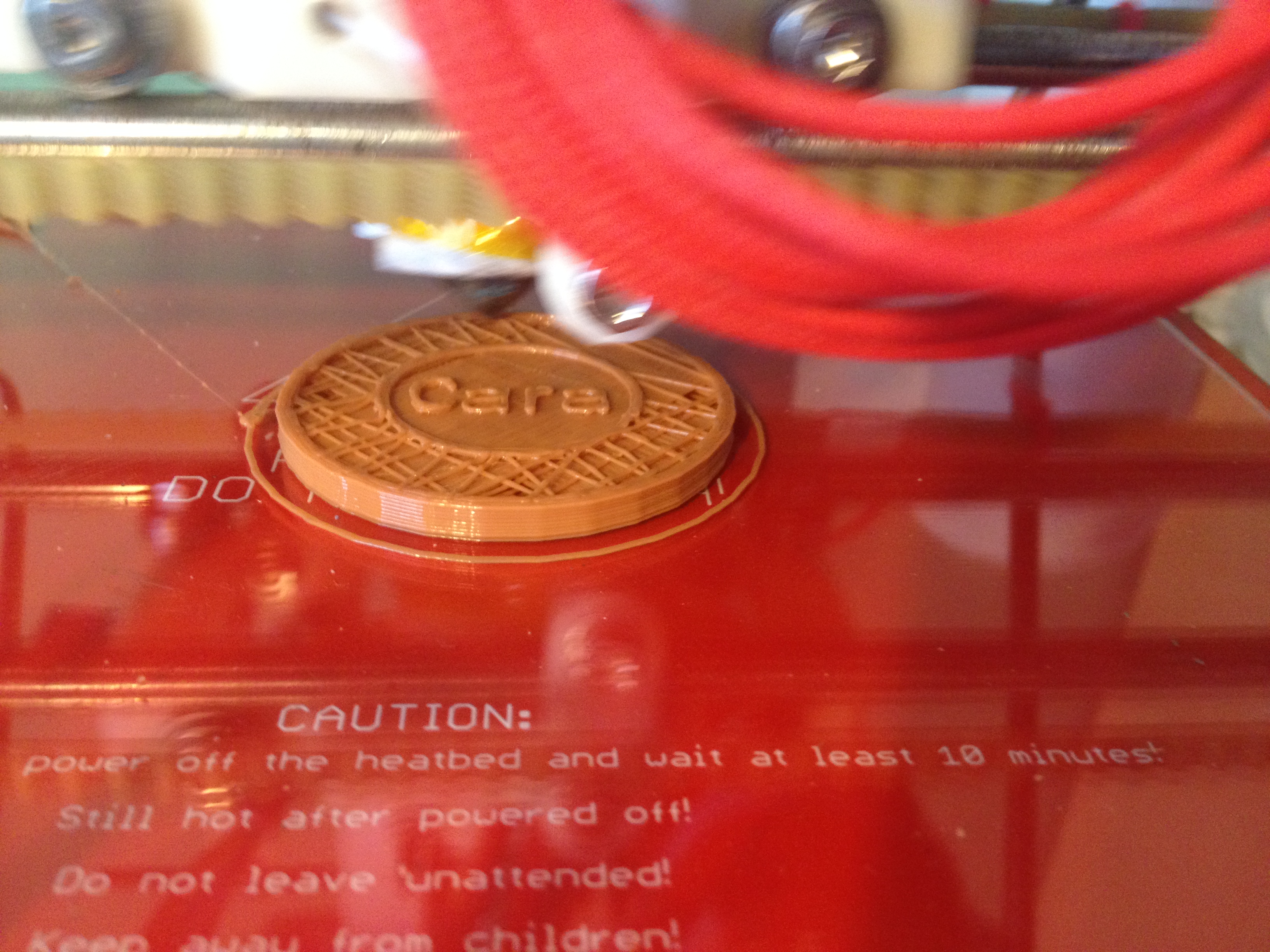
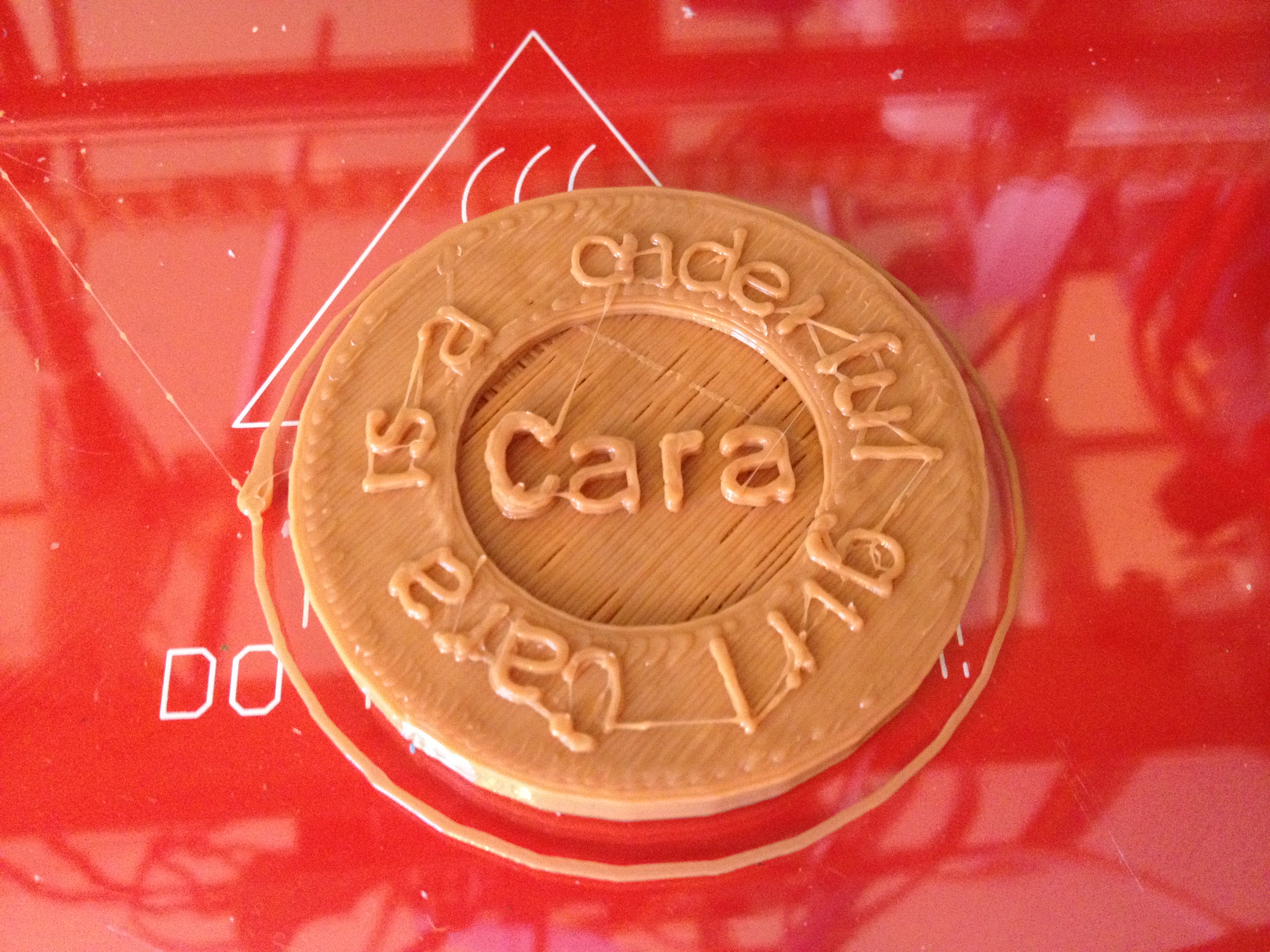
Cara’s Coin – February 5, 2014
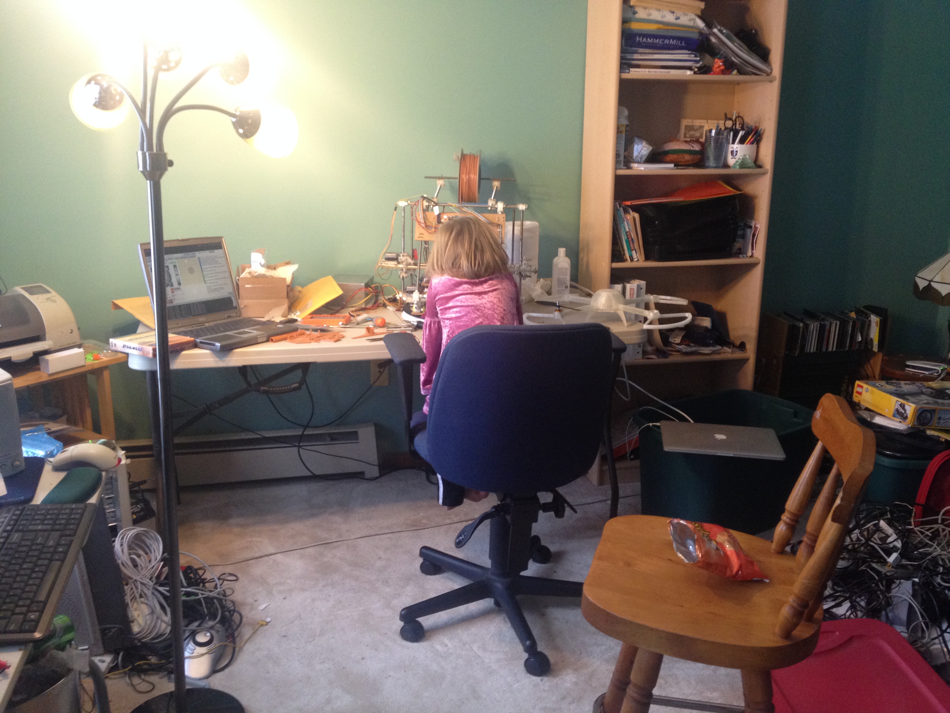
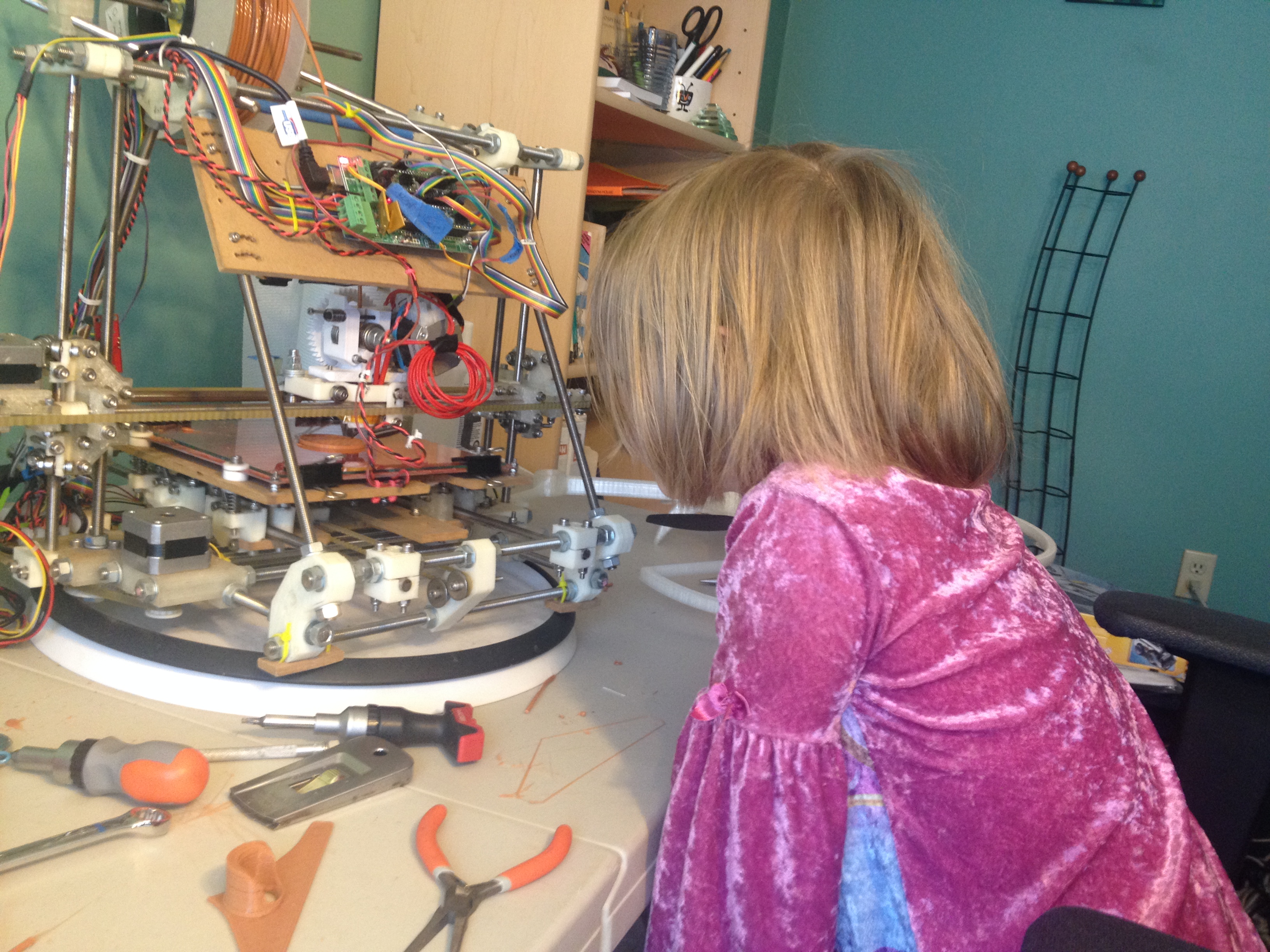
This day was a snow day (and since the lab is closed, I wasn’t allowed to work from home). As a result I spent the day with Cara, both watching Star Wars Episode IV and doing RepRap printing with her. We started the day with her deciding what she wanted to design. We looked at the demo code within Write.scad that draws text, and Cara realized she wanted to make a coin. We made this coin, which says Cara in the middle and is supposed to say “Cara is a wonderful girl” on the outside, but for some reason the W didn’t survive the print, so it says “Cara is a onderful girl”.
Since we designed this, this was close to being in the spirit of the original thing-a-day tradition (although I was unaware that I had misremembered the tradition of printing vs designing until Febrary 8th).
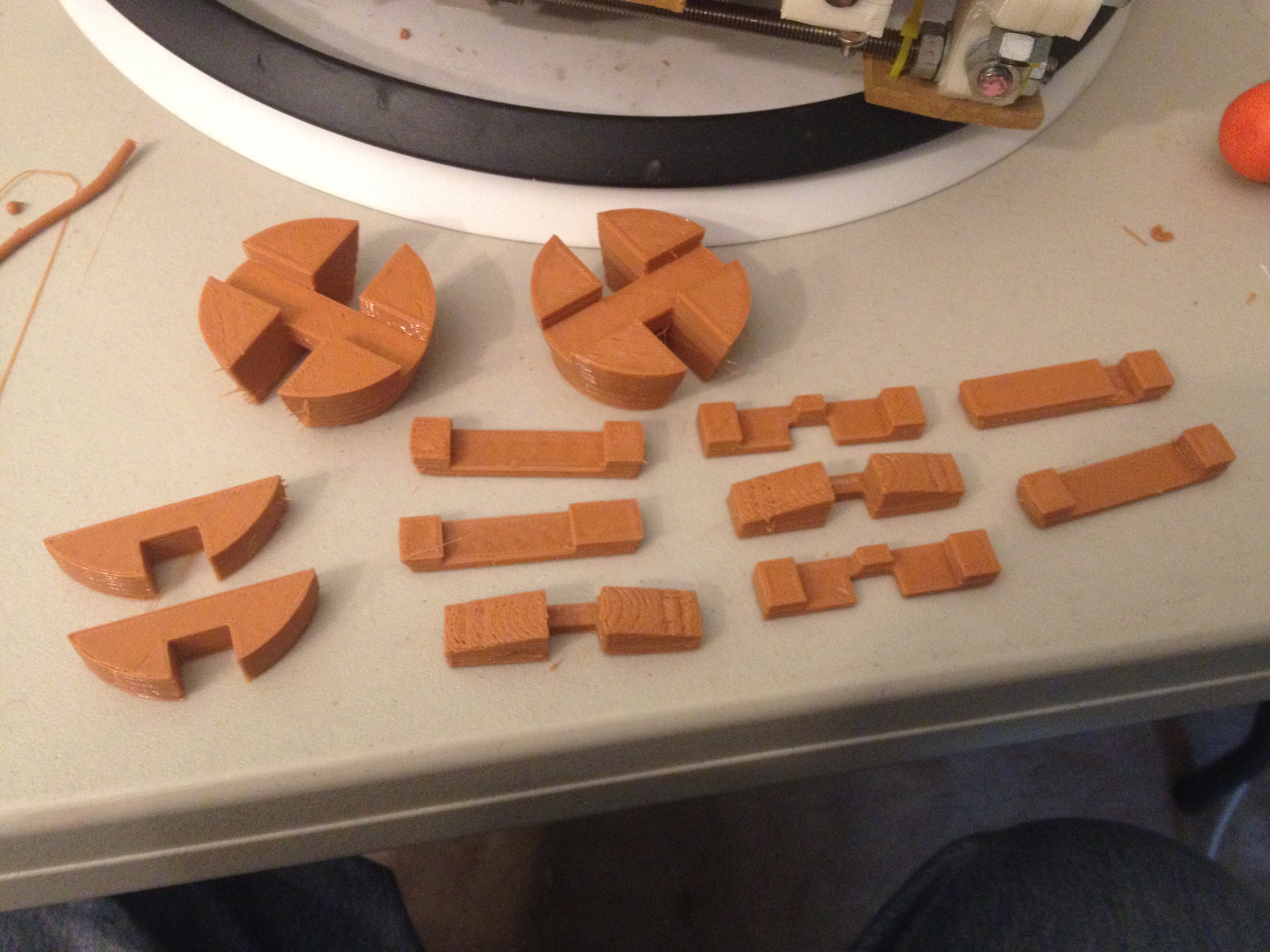
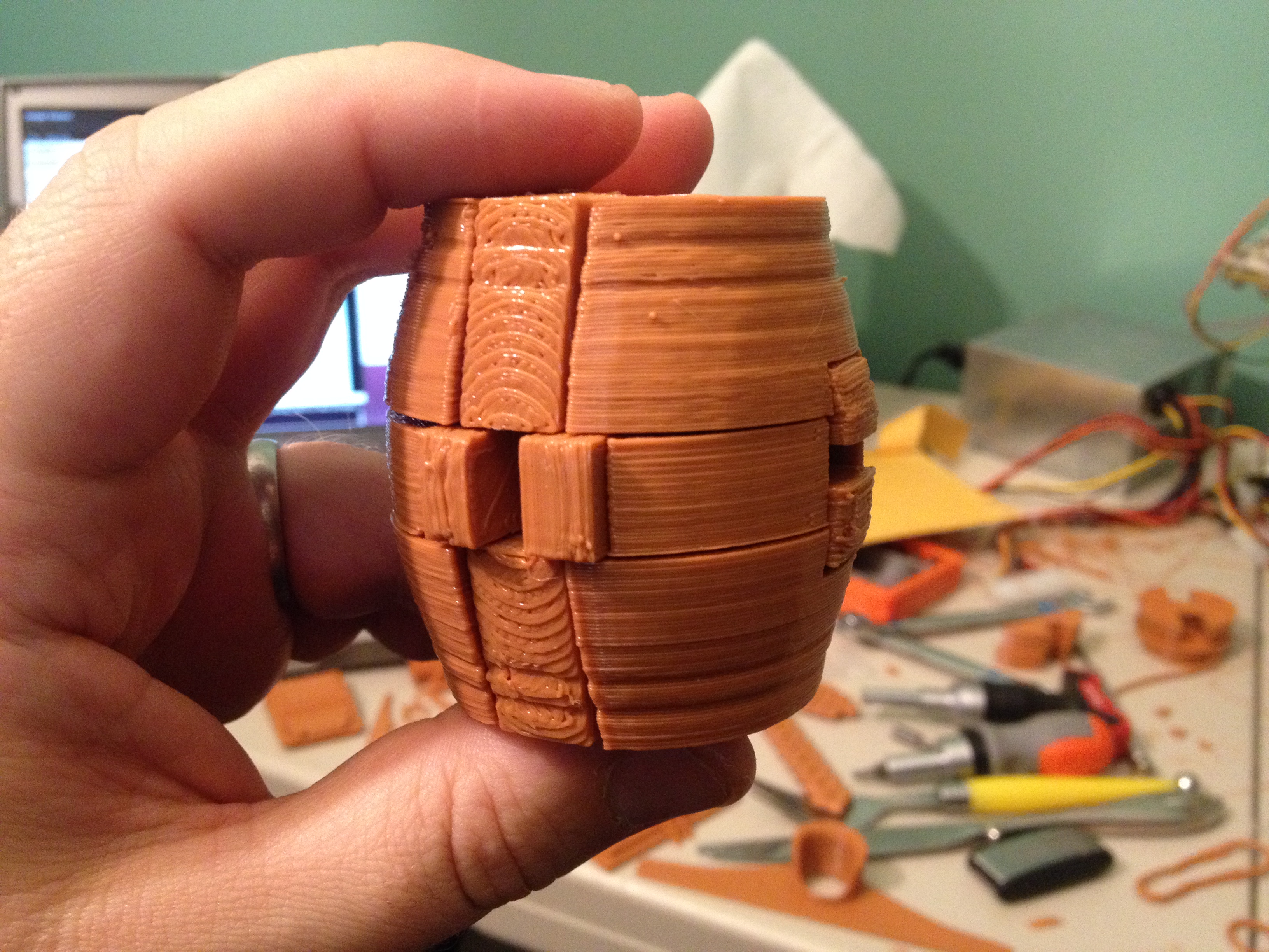
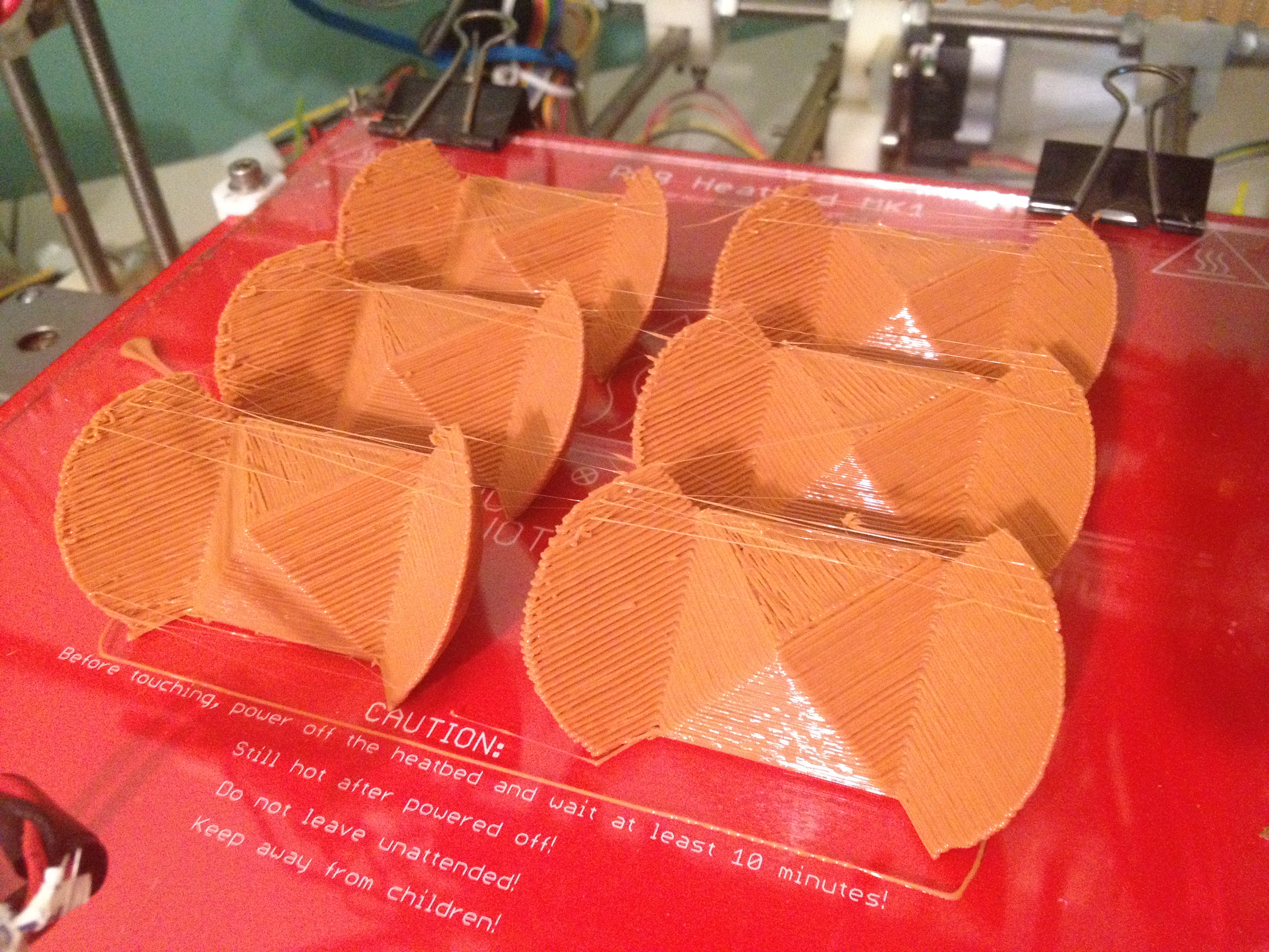
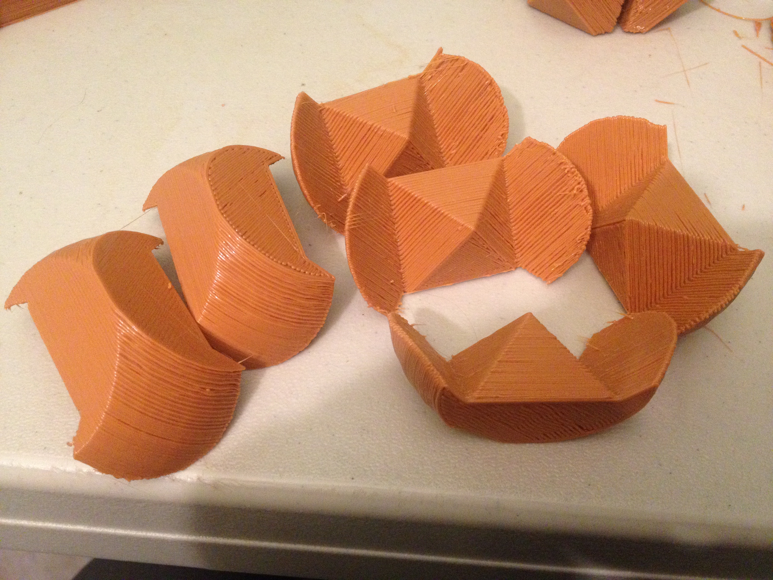
Barrel Puzzle – February 6, 2014
I created two plates for all of the parts of this Barrel Puzzle, and printed them all (two prints, mostly unattended):
The tough part is getting a picture of it assembled, because that requires solving the puzzle. 🙂 I probably need to file down some of the parts, and I’m afraid this was one of the first parts to really suffer from a weak-z-axis problem I’d probably been having all week, as parts weren’t always turning out as tall as they should be.
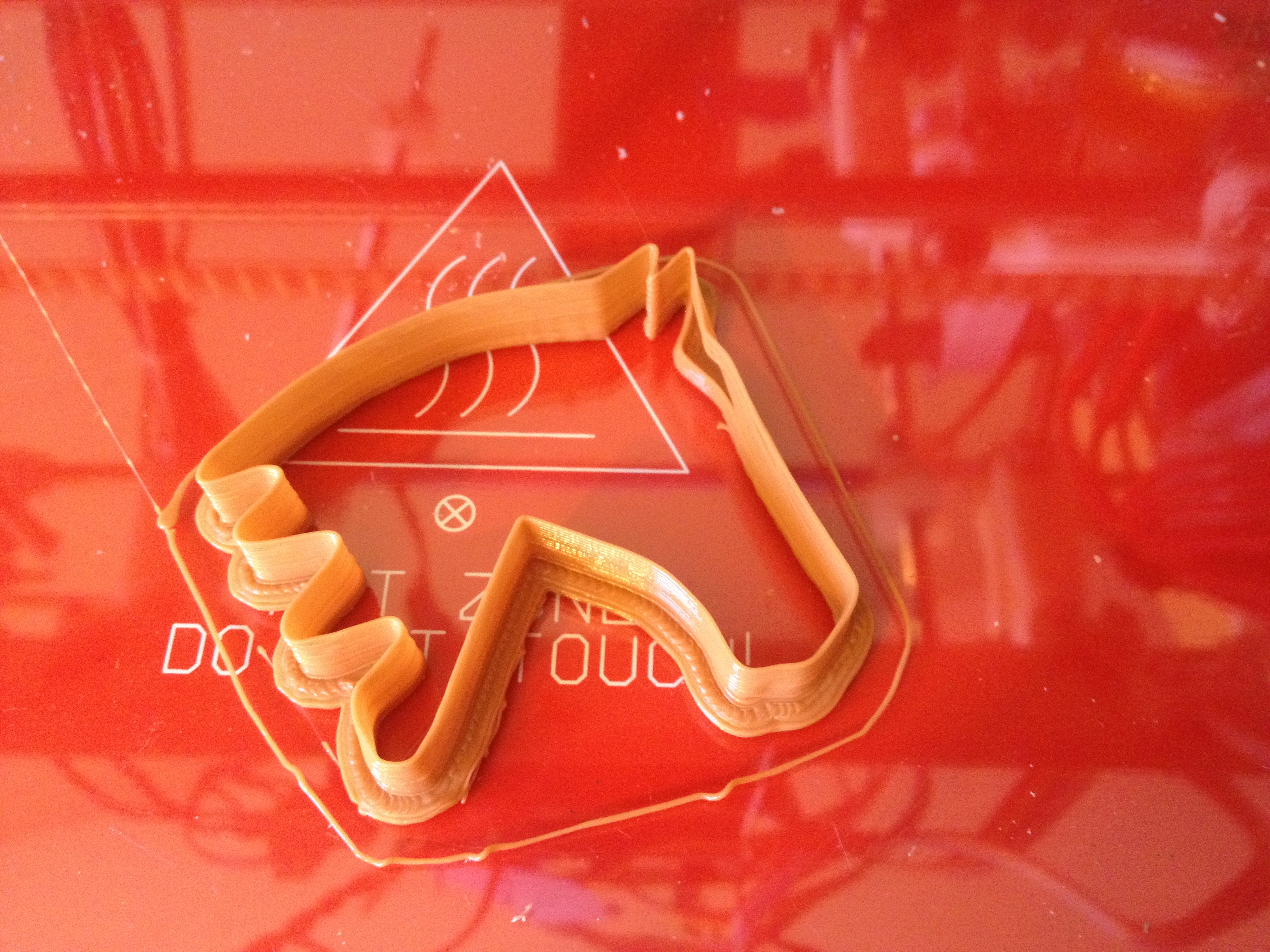
Horse, Horse Cookie Cutter – February 7, 2014
Friday I had a bit more time as I’d finished my hours for the week early in the day. Alicia’s birthday was the next day (Febrary 8th), so I wanted to try printing her something to do with a horse. The safety net print was a Horse Cookie Cutter, which we’d use to make sugar cookies on her birthday:
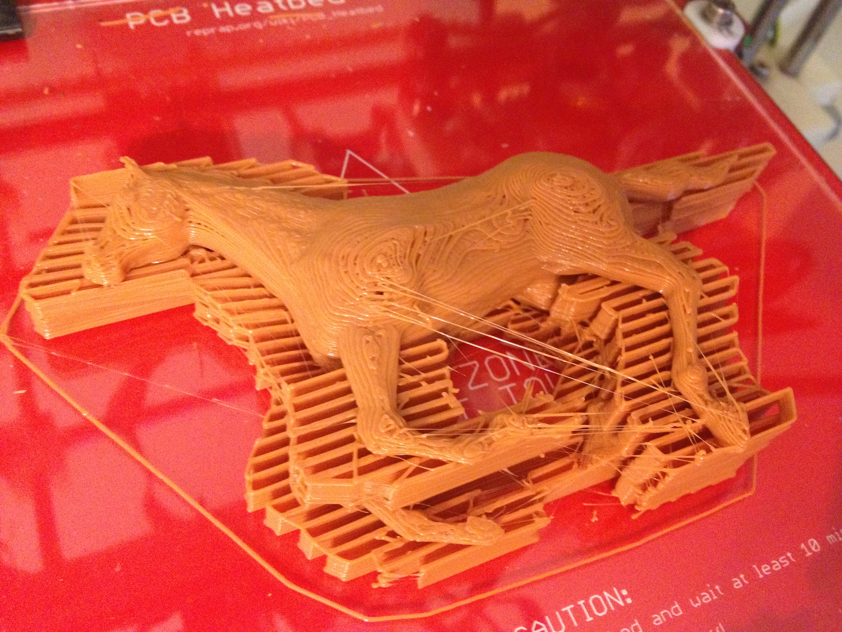
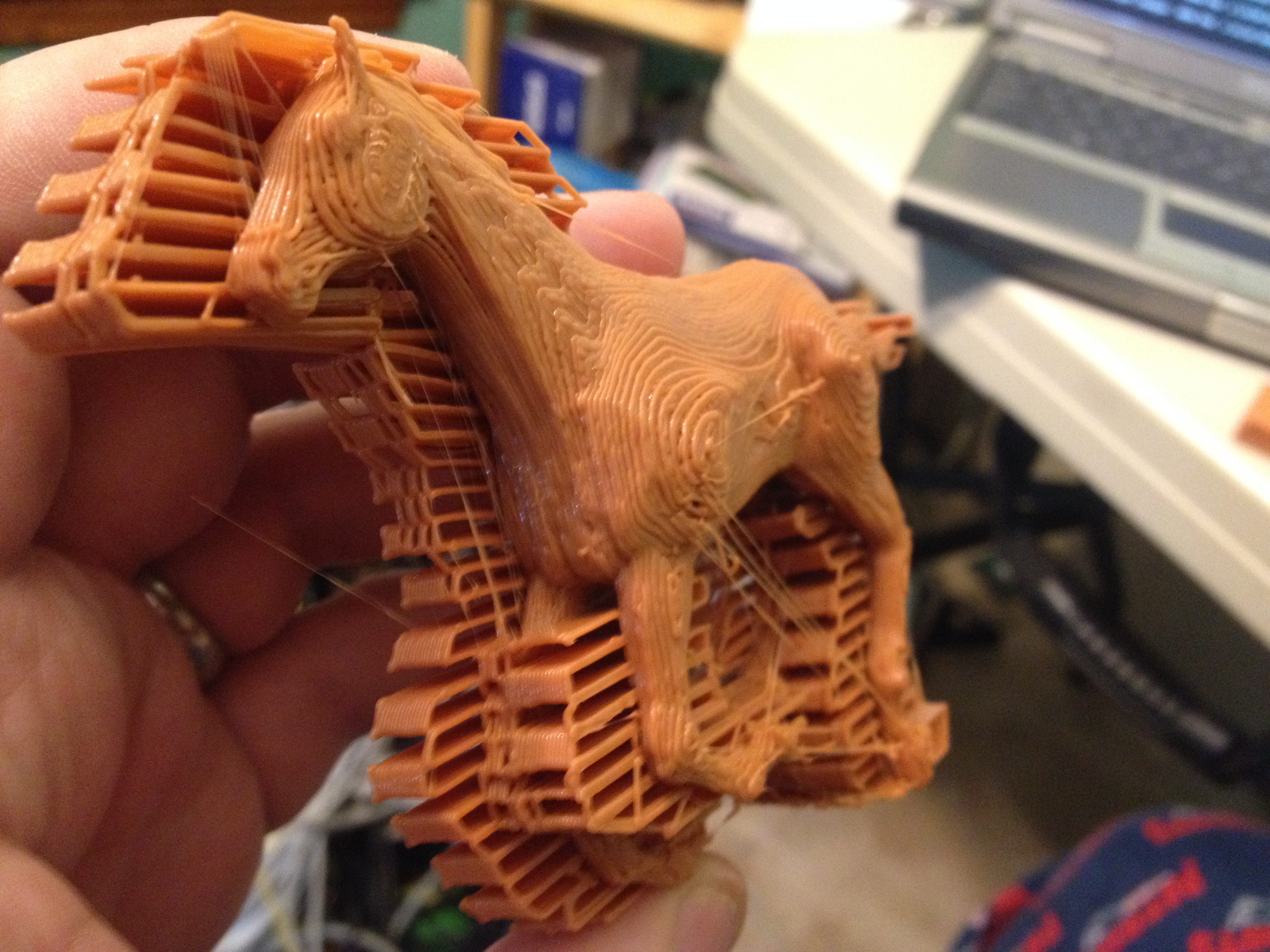
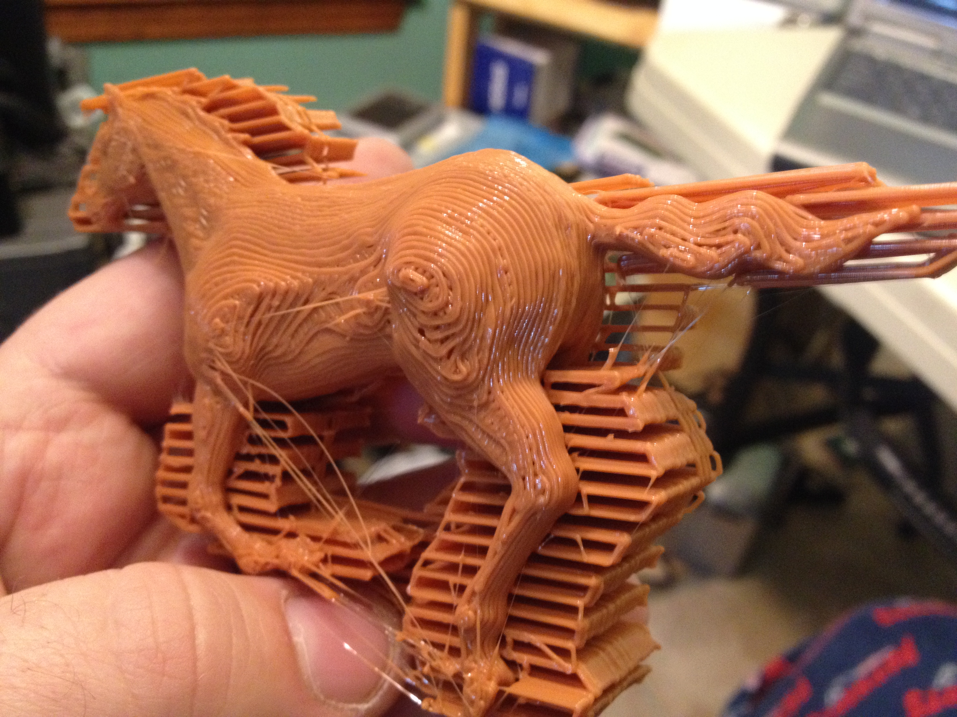
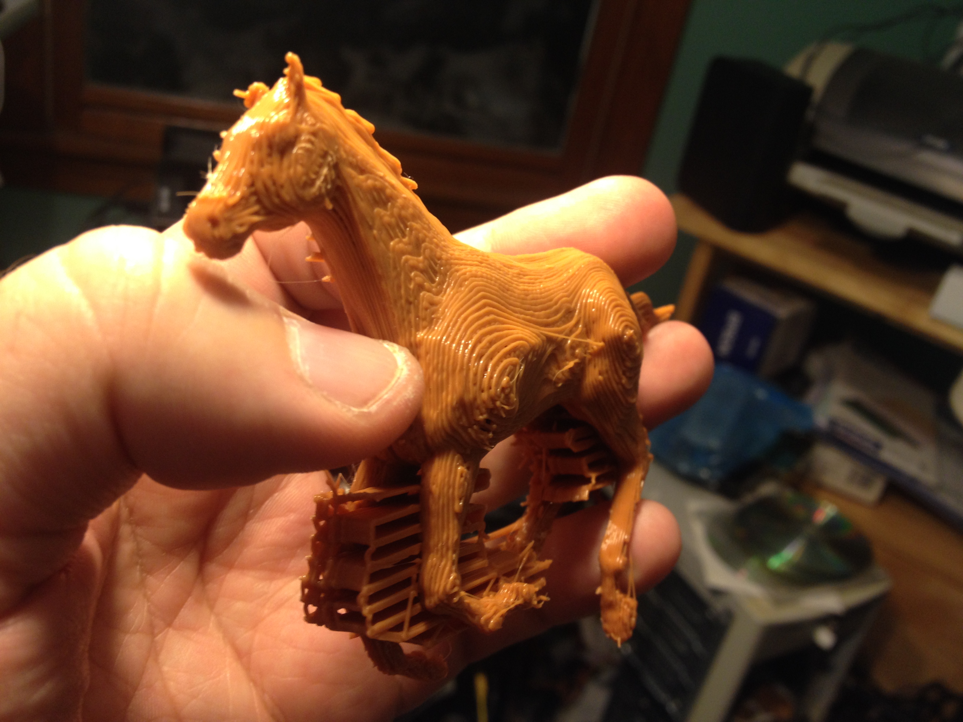
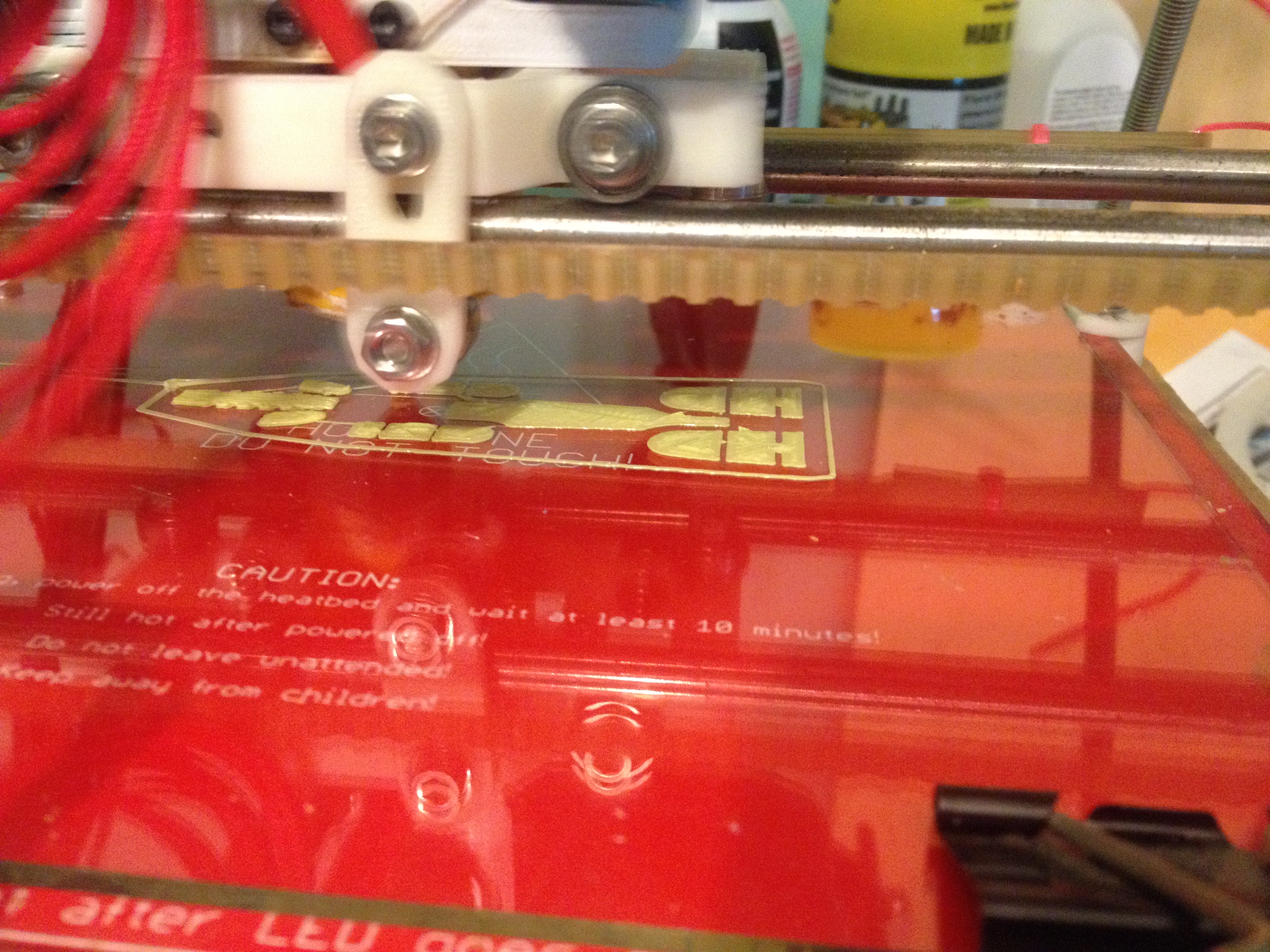
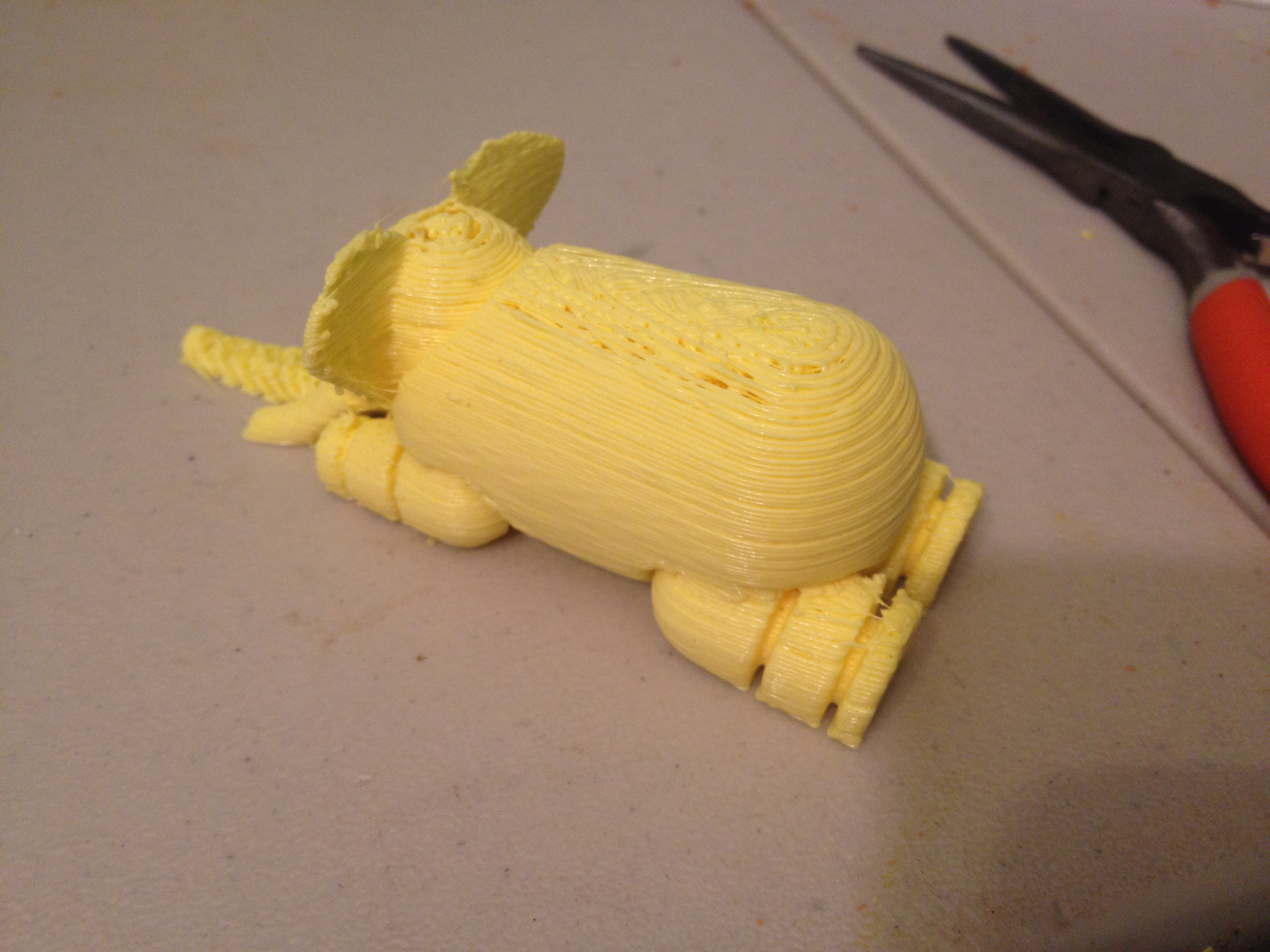
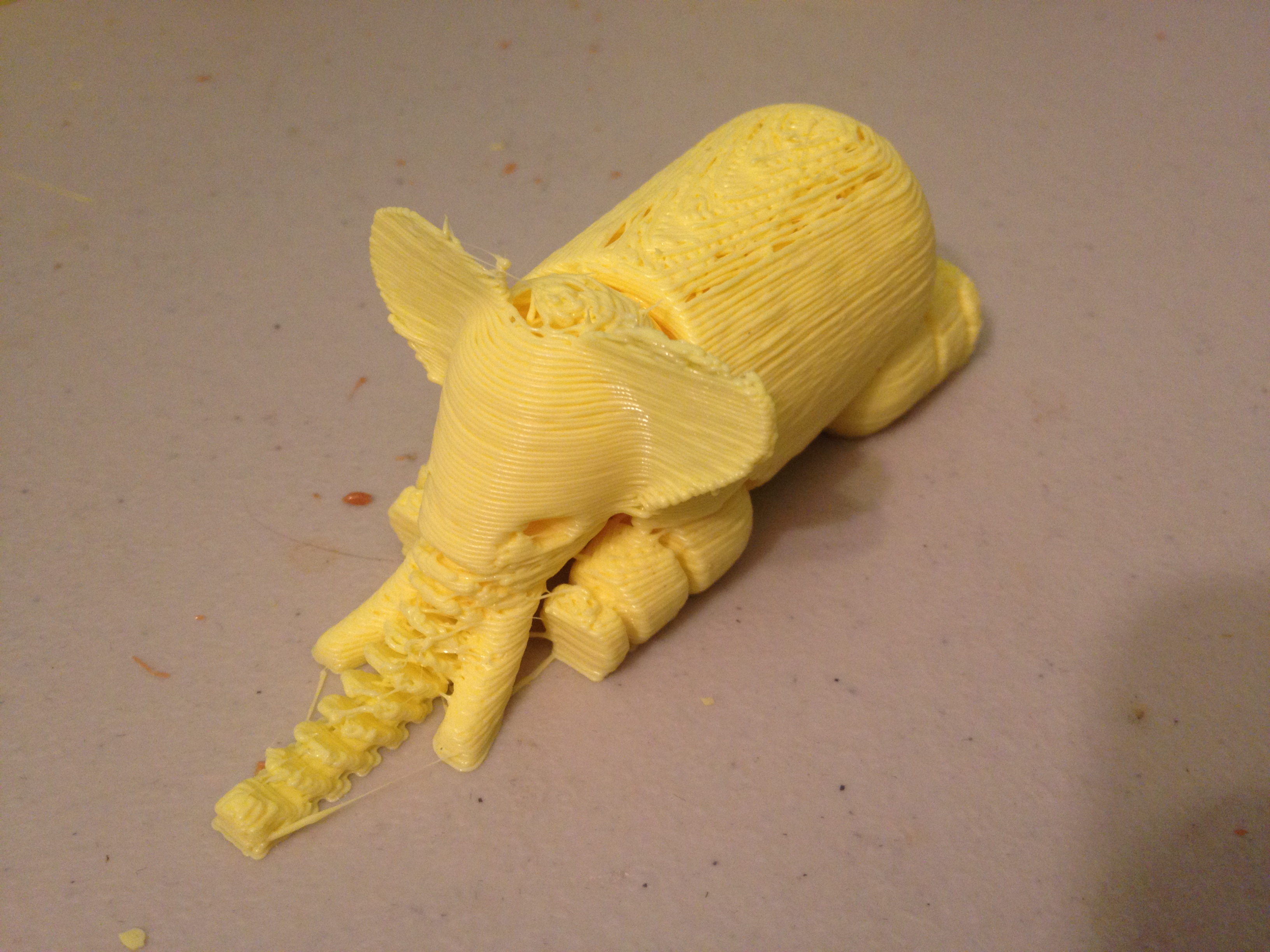
But the real thing I wanted to print was an actual horse model. I’d seen a few on thingiverse in the past, some of which involved printing two halves of a sliced horse and super-gluing the pieces together. I decided instead to try printing one with supports. I only have one extruder, so I had to print the supports out of the same plastic and break them off later with pliers.
I rotated the model on its side with meshlab, moved it up above the xy plane with plater.py, and printed it with supports (in Skeinforge/SFACT’s Raft module, choosing “support everywhere”). As far as I can remember, this was the first part that I’d ever printed with support on my RepRap (I’d printed with support once before at work, printing the Enterprise from Star Trek: The Next Generation, upside down with support, but never on my RepRap or with Skeinforge/SFACT).
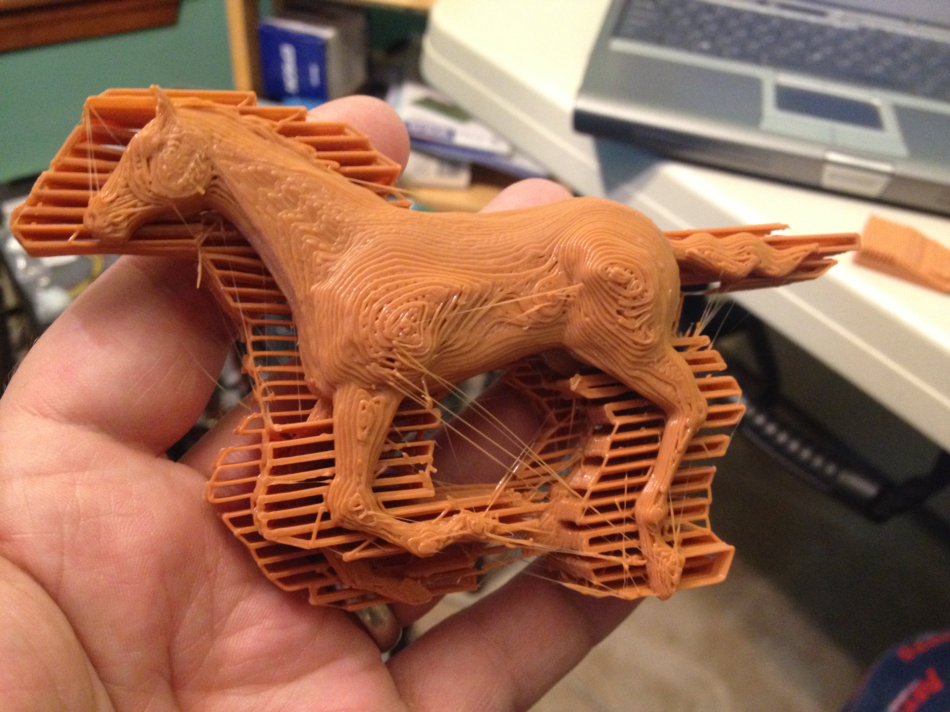
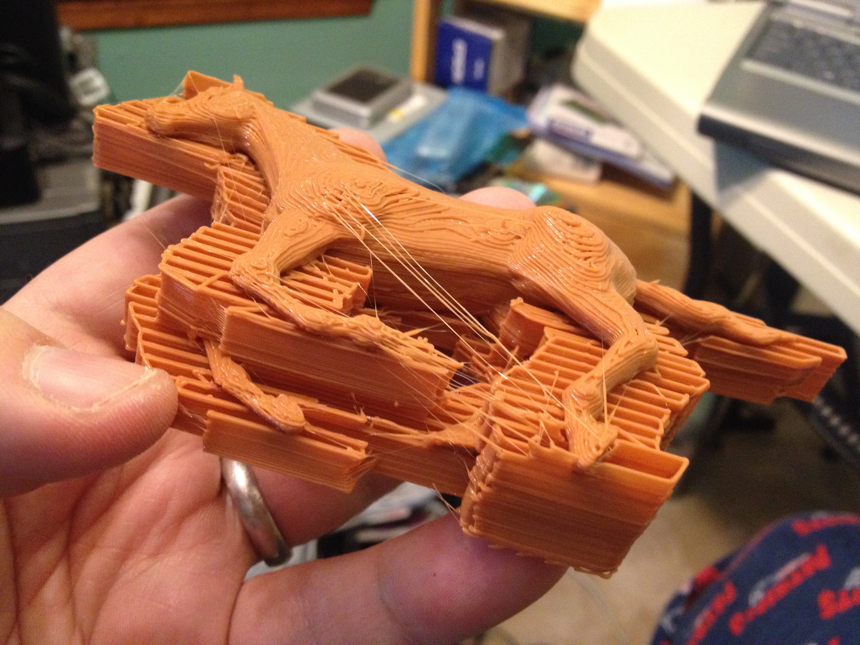
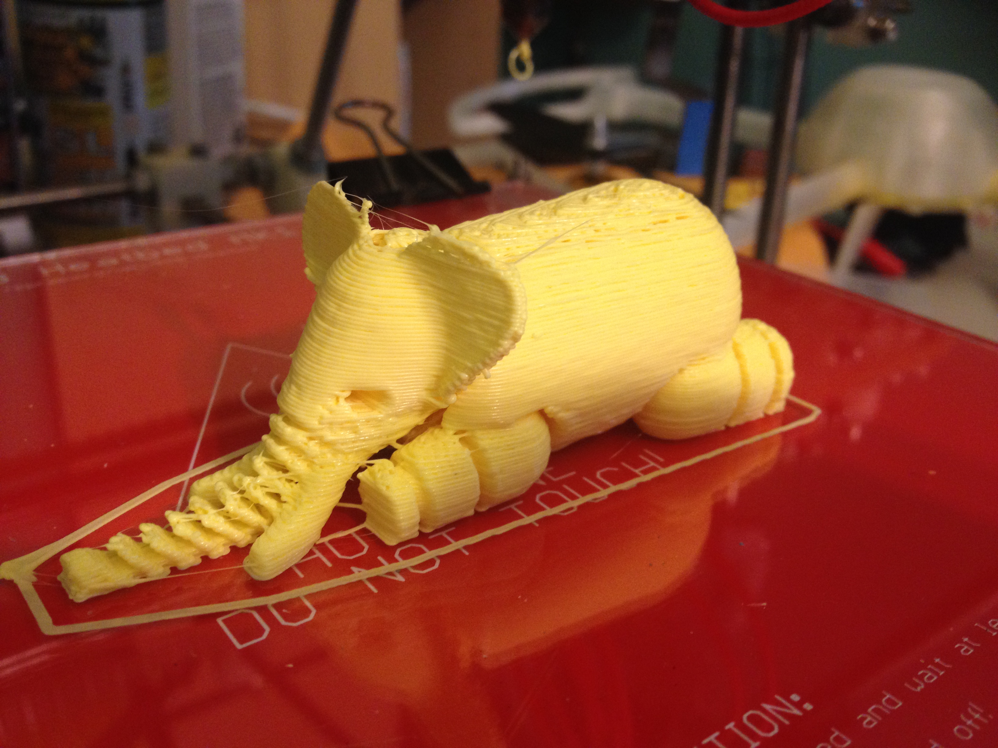
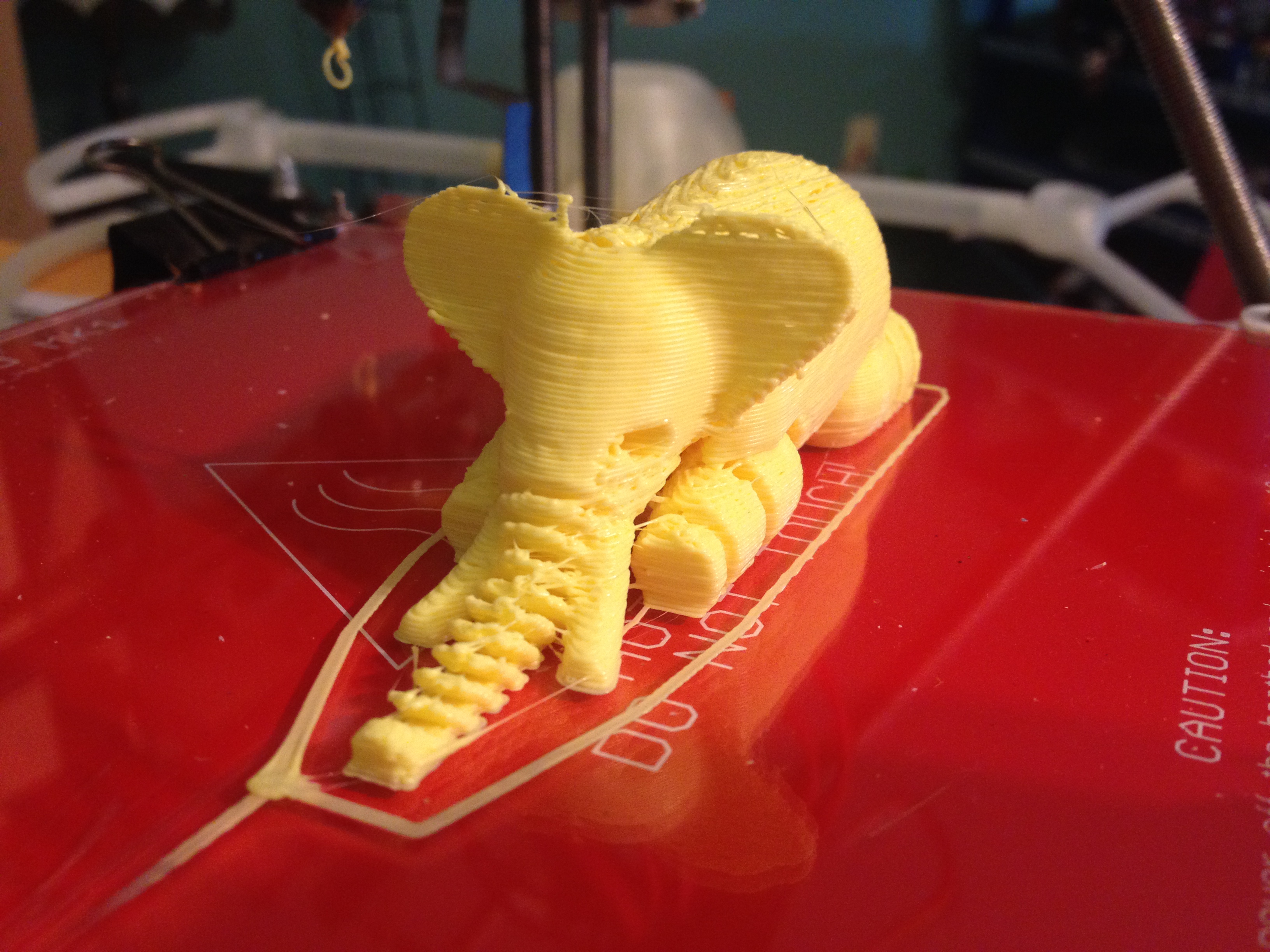
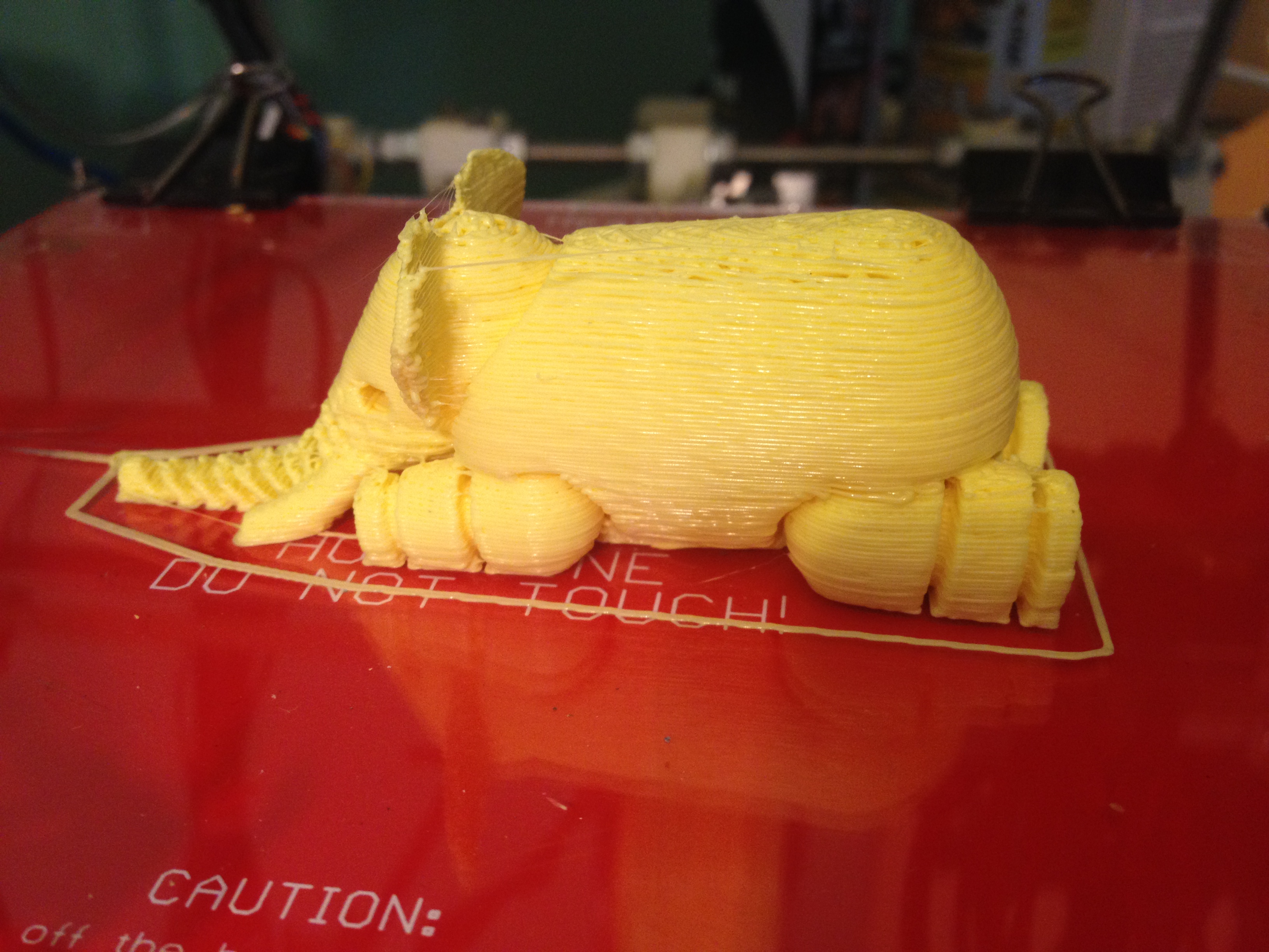
How cool does this look?
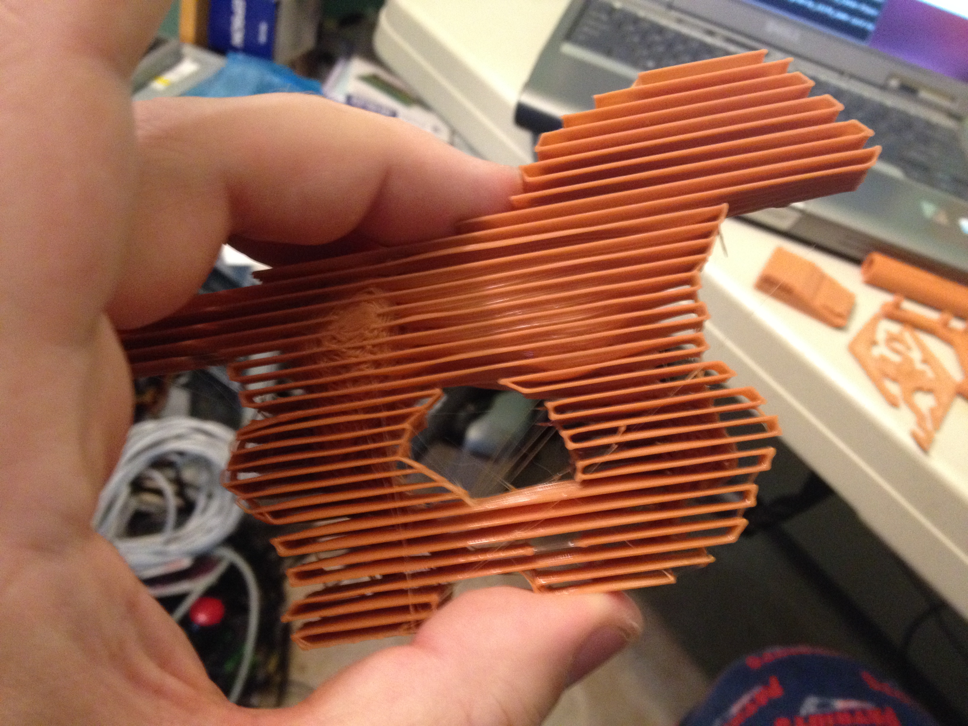
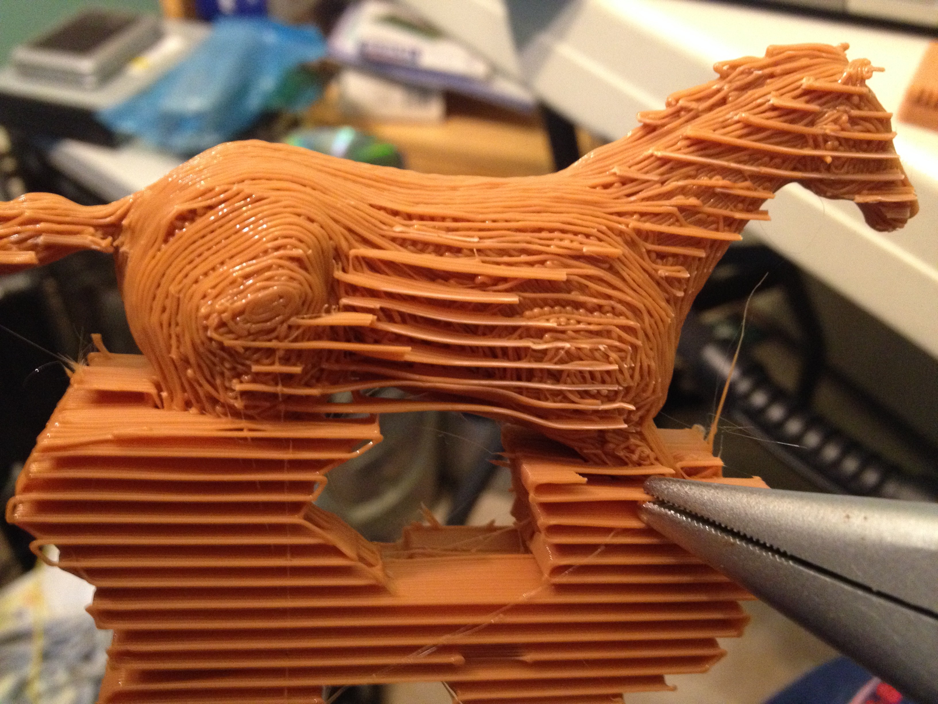
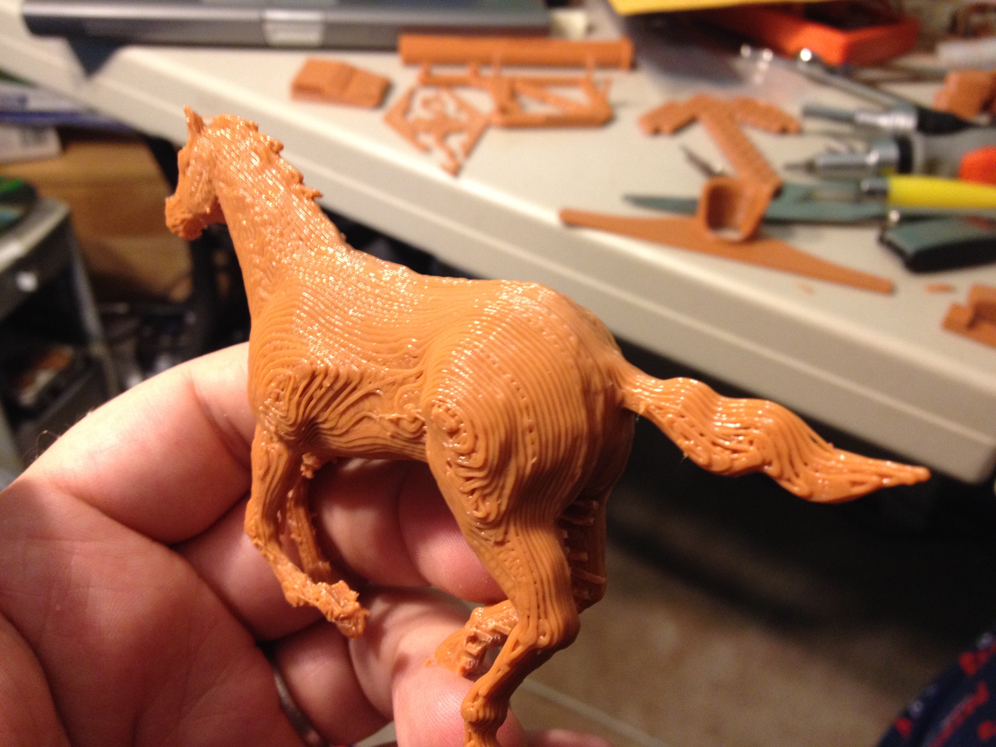
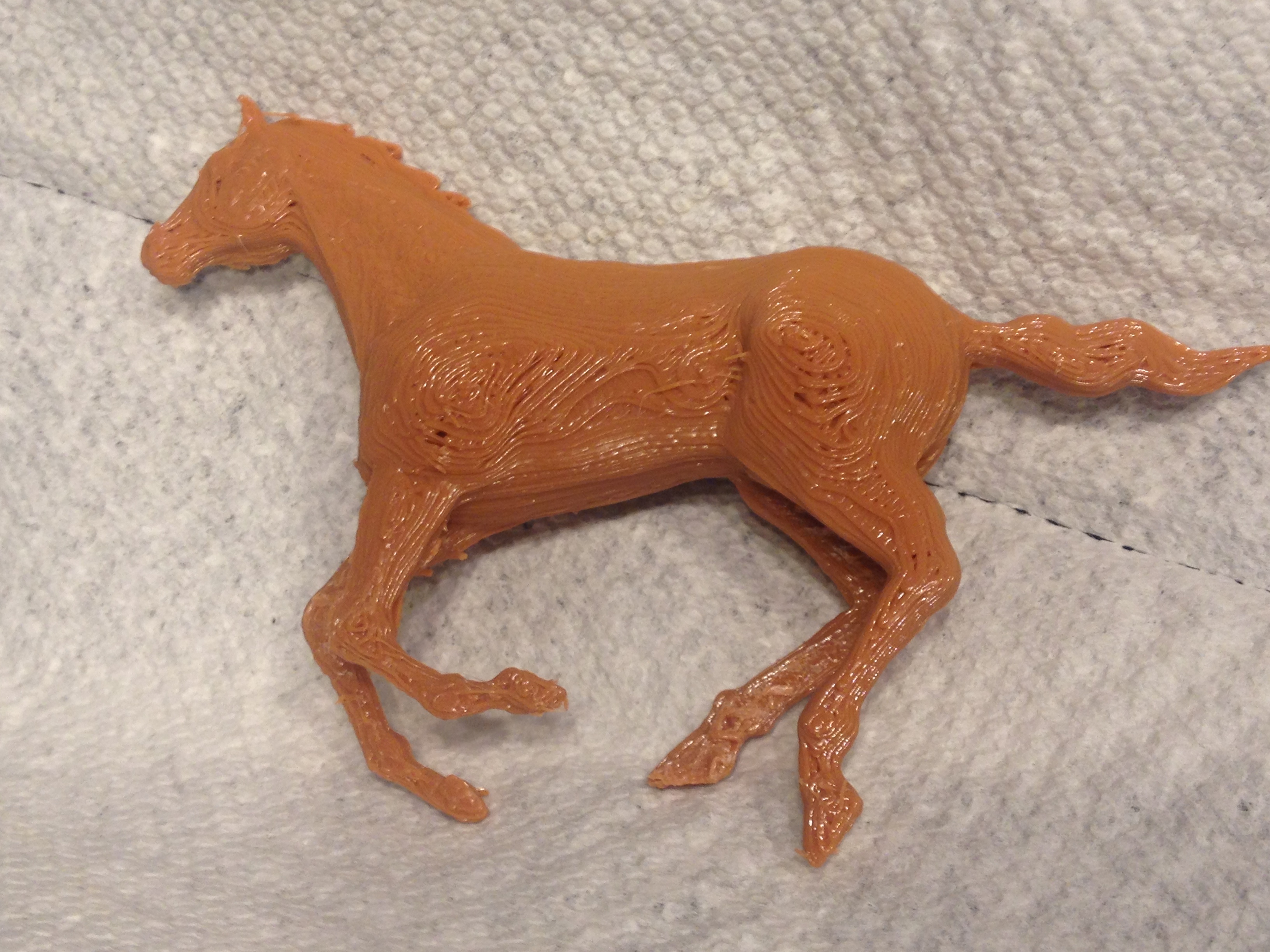
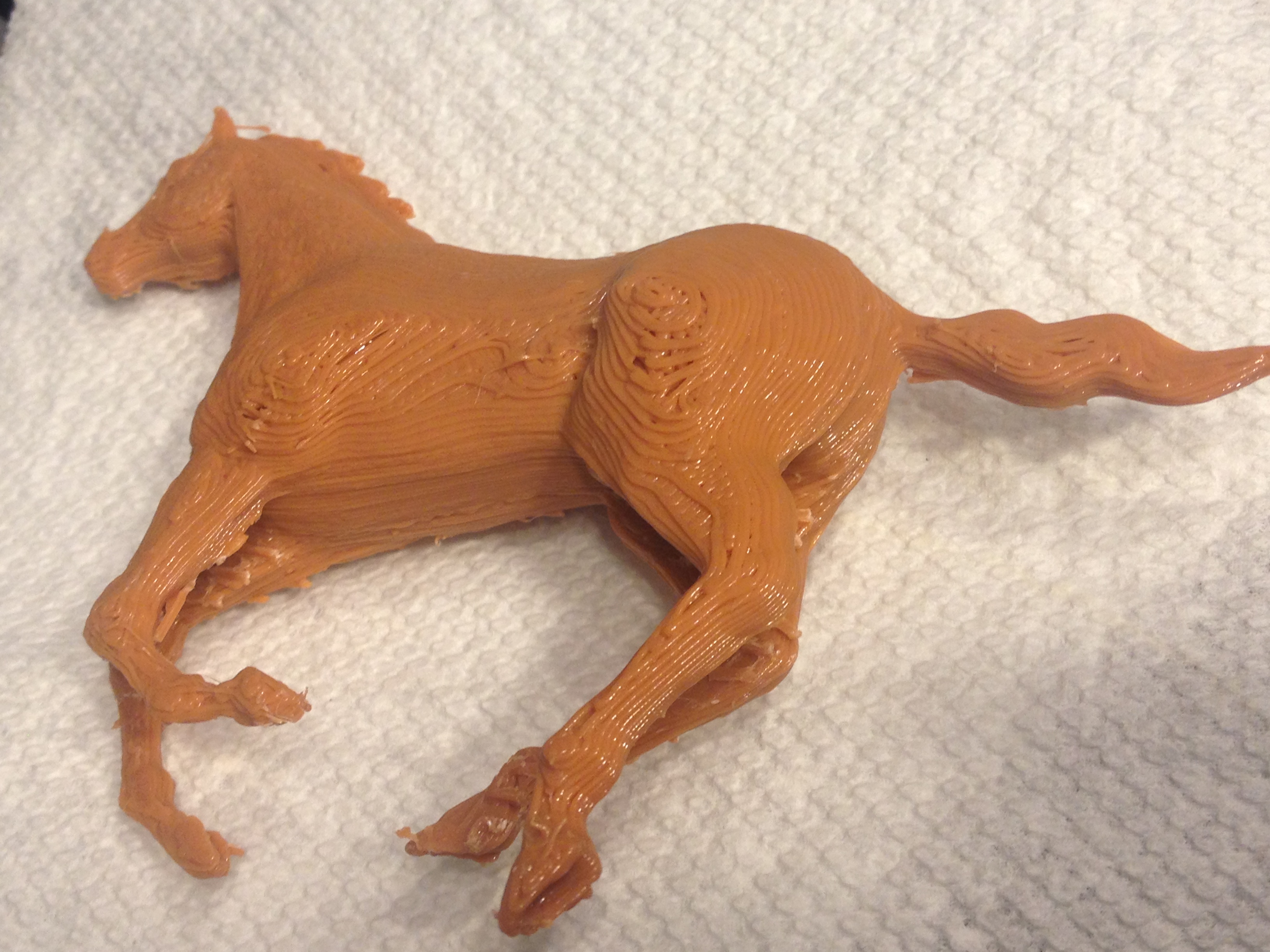
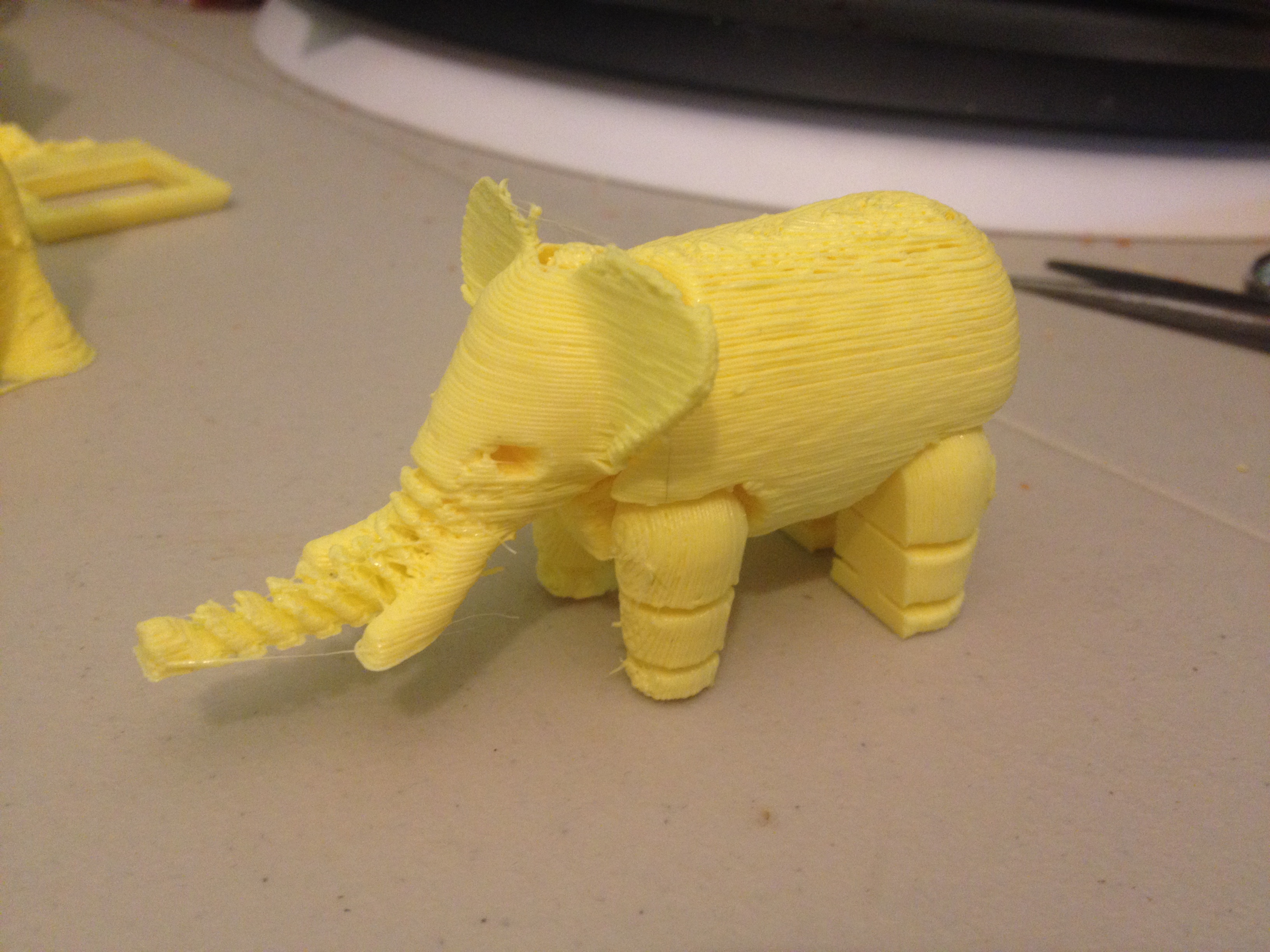
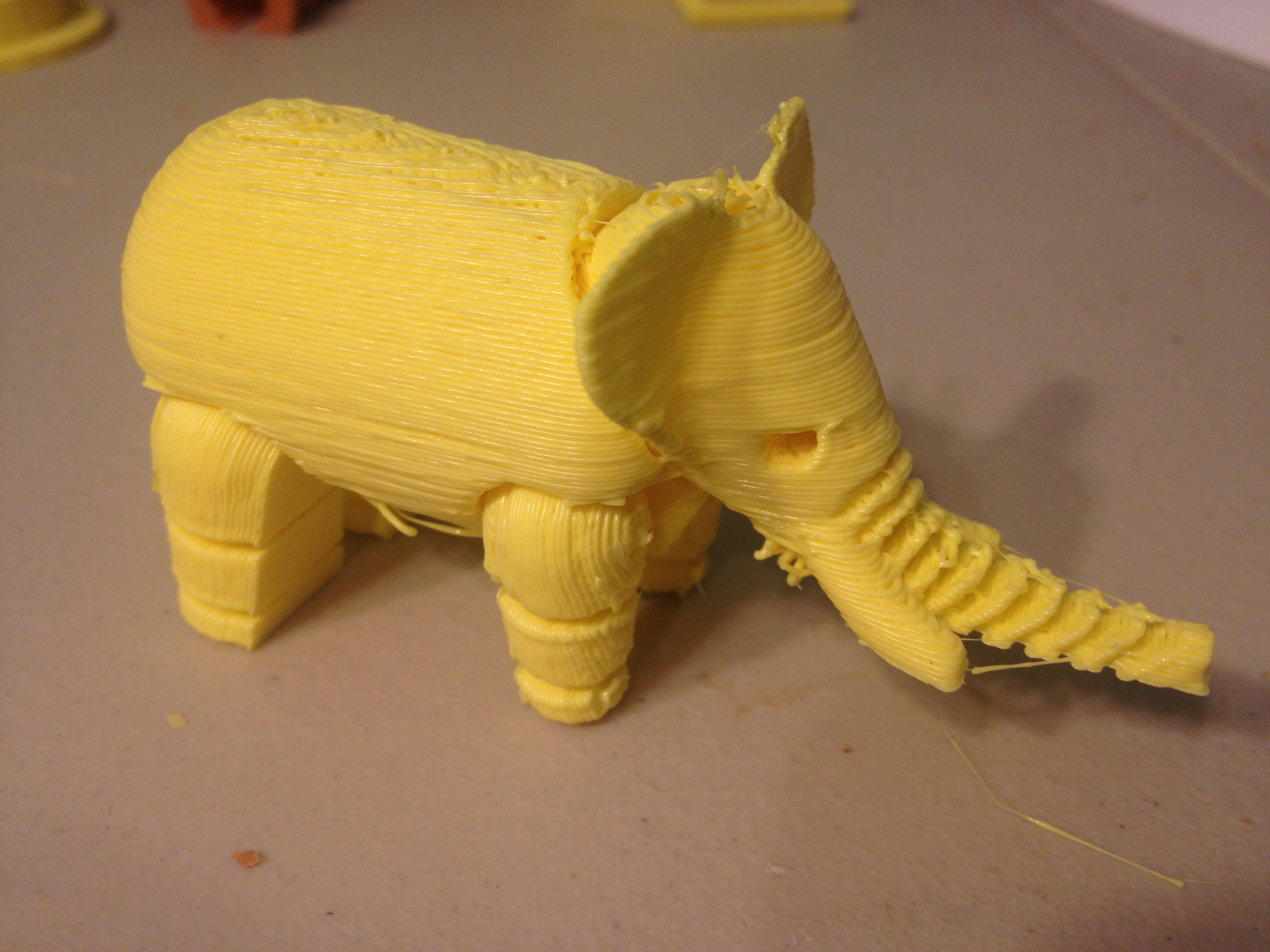
I pulled off the support material with pliers.
I think it came out incredibly well.
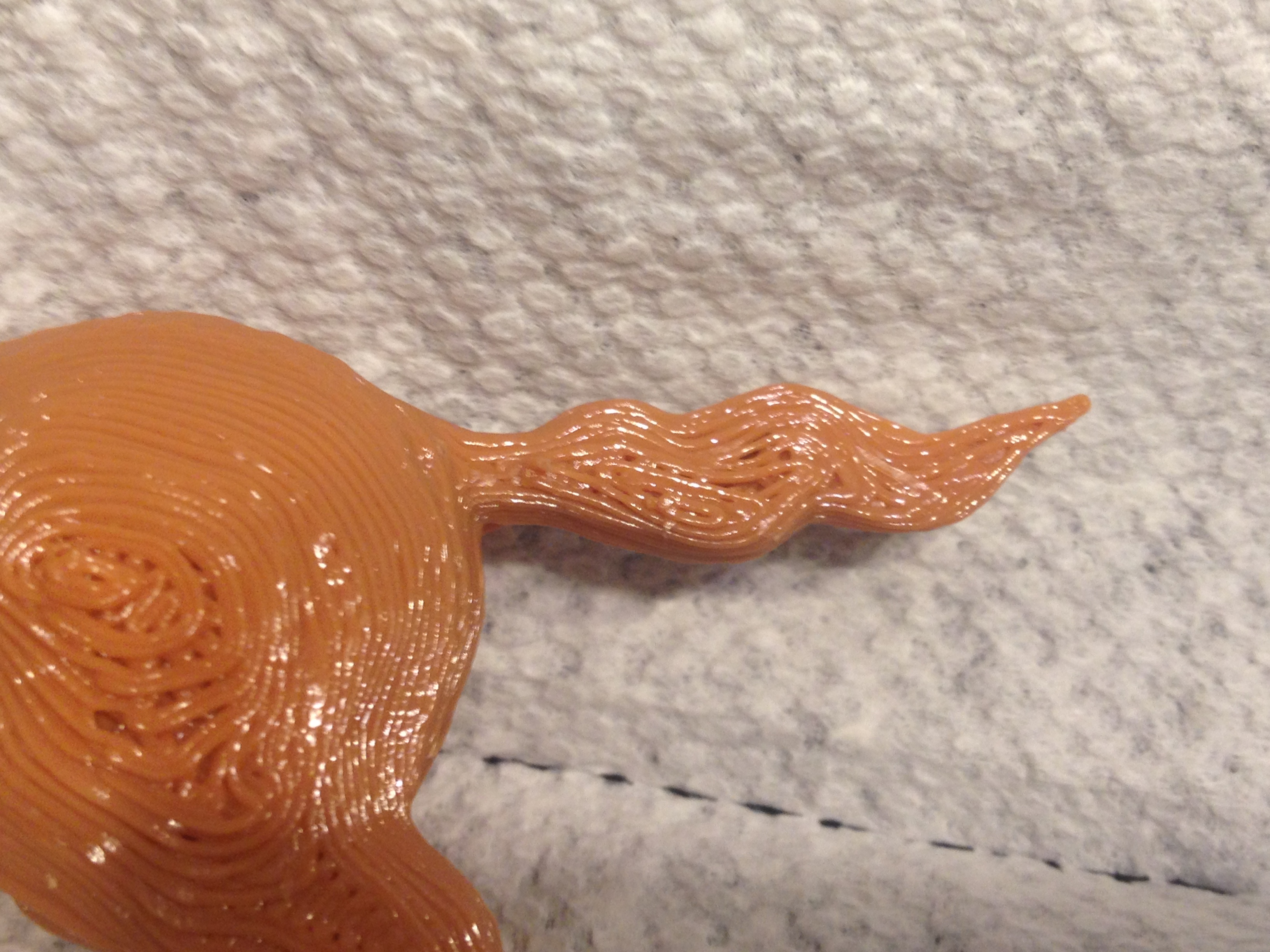
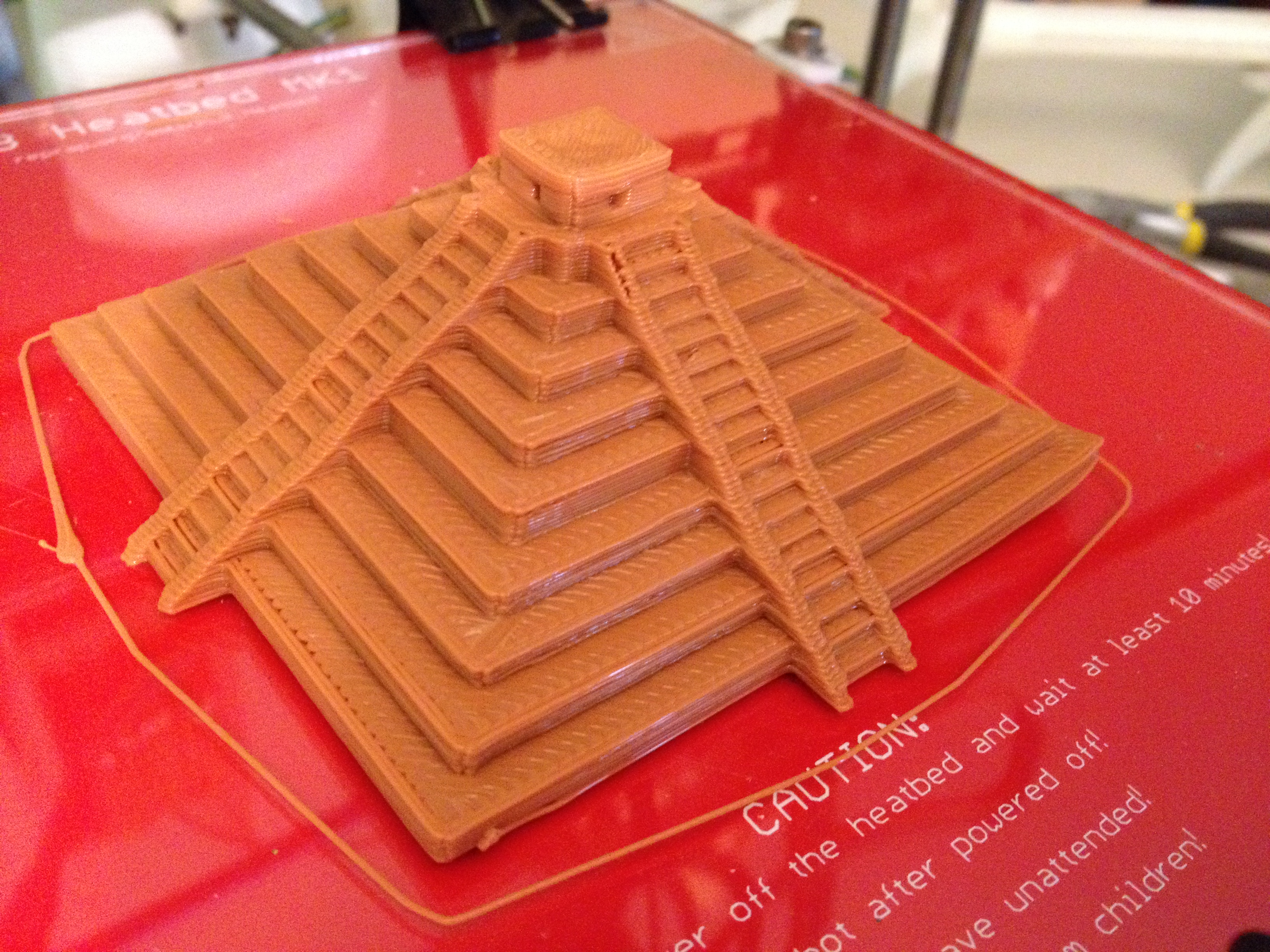
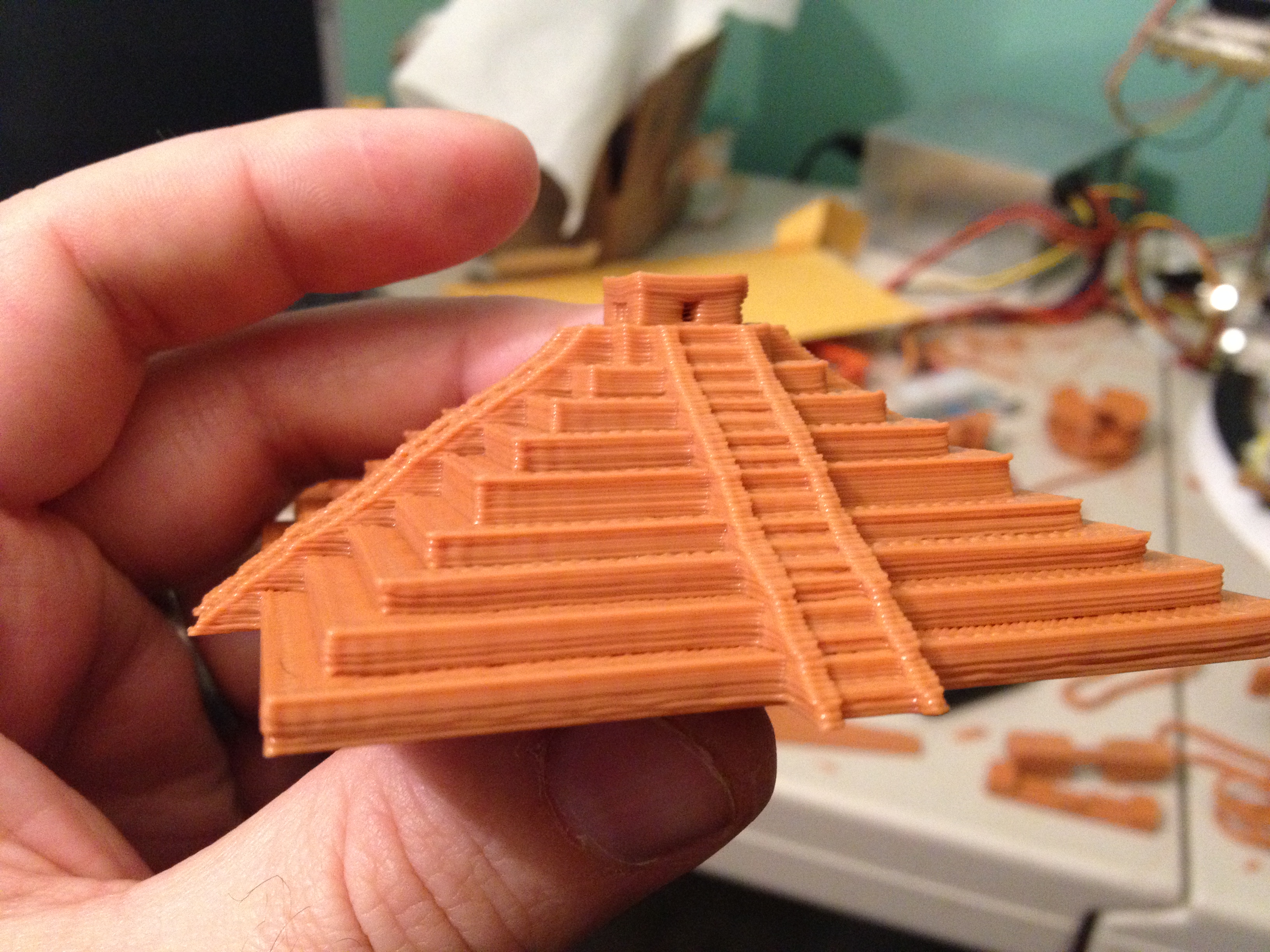
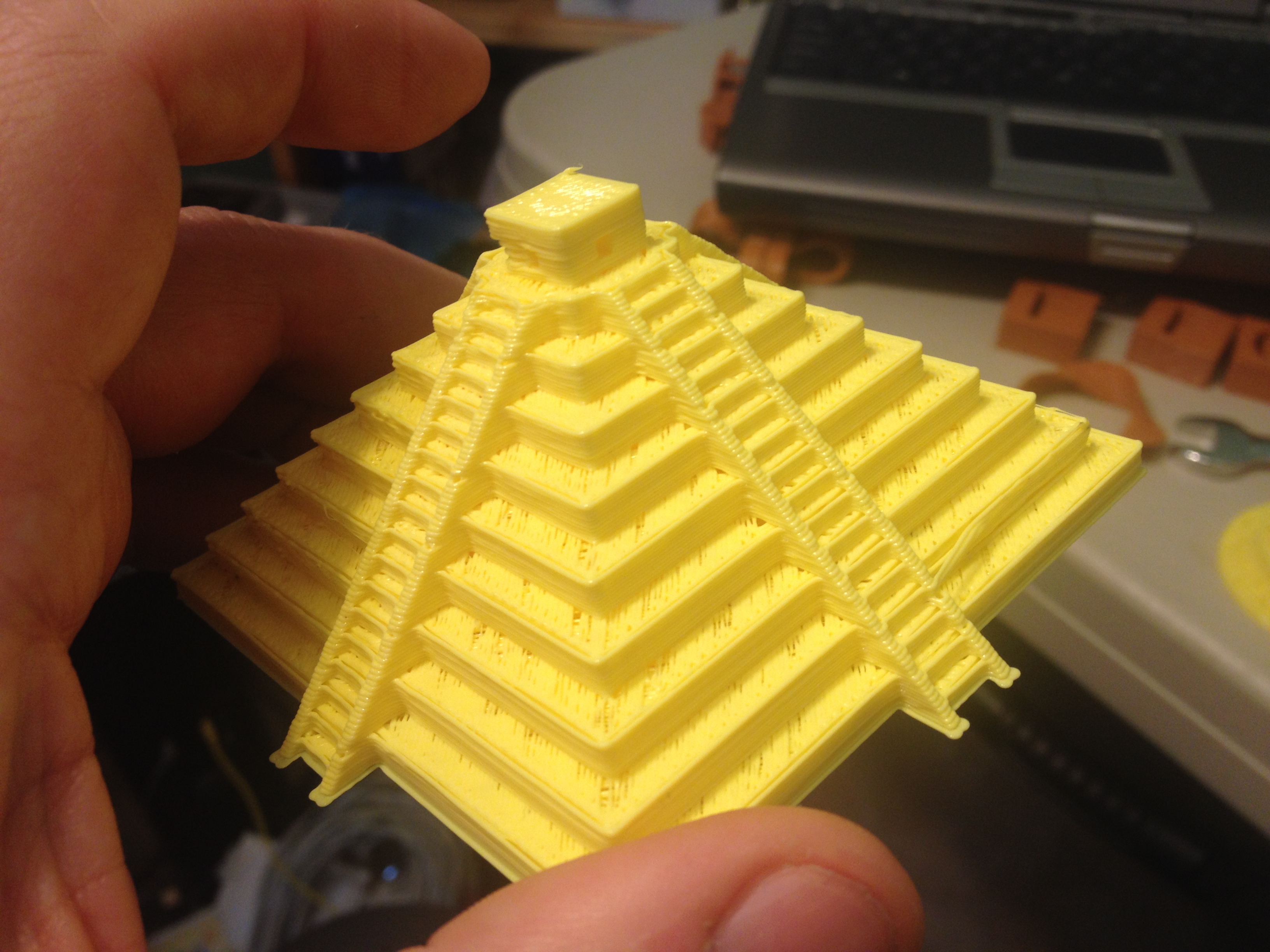
Chichen Itza (from Matrix Buildings) – February 8, 2014
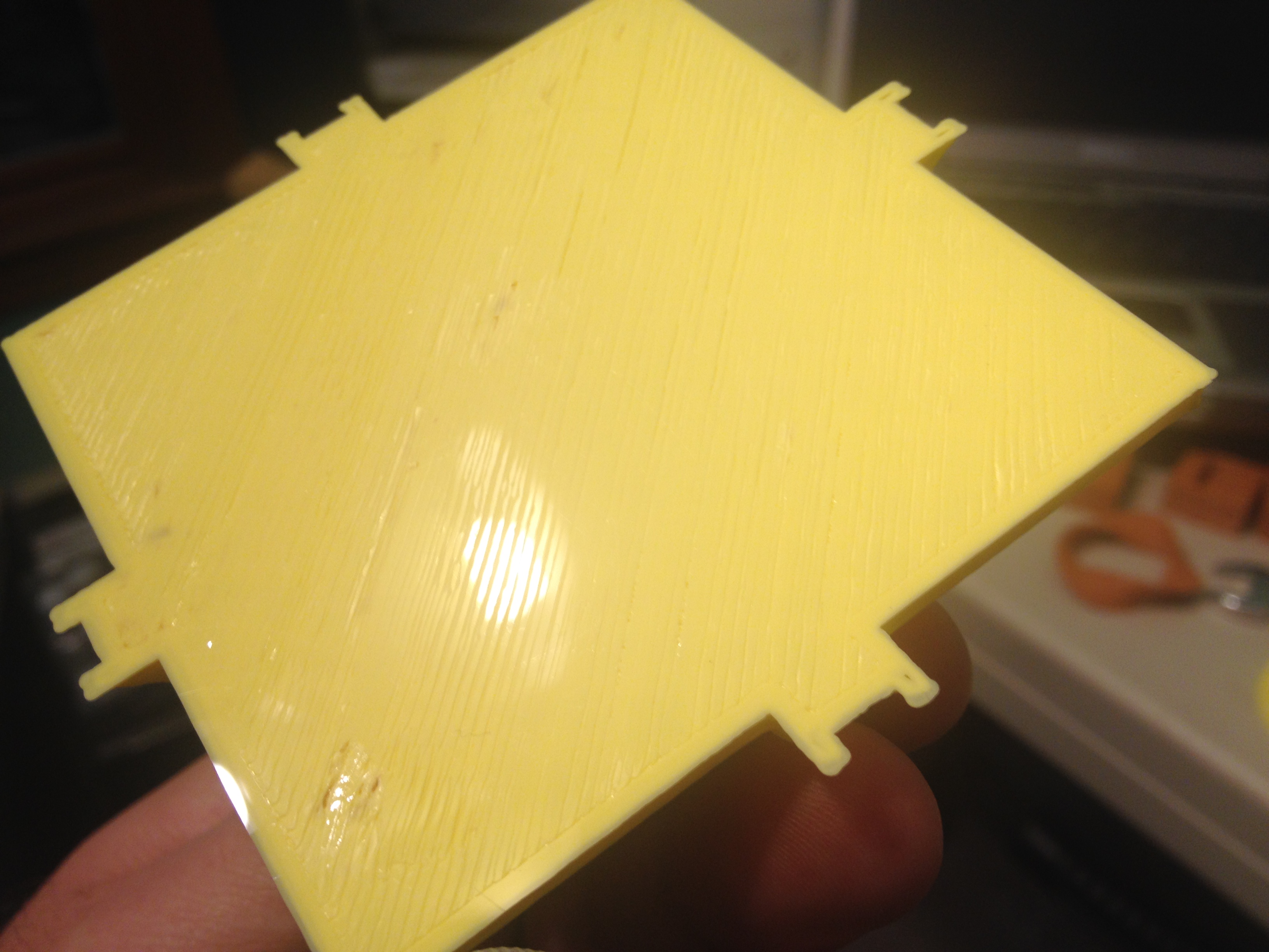
After midnight (so technically on February 8th) I started a print of Chichen Itza from the thing “Matrix Buildings“. This was one of the most pronounced failures of my now-weak Z axis, as it’s not nearly as steep as it’s supposed to be, and one of the steps is even taller than the others. Still, it looks pretty cool (even if one corner warped up a bit):
Here you can see that it wasn’t as tall as it should be, because of the Z-axis problem I mentioned above:
I had previously tried to print this once, half way down this older post, but didn’t even remember what it was after a failure.
This, by the way, was the day where I finally had time to start typing this post up.. The kids have friends over so the TV is occupied, and the desire to print something today is slightly less because I’d be using up something I could print on later days! Aaah! The real crazy part though is that I’m titling this without any “Four, no, xx months, part x of ?” garbage. But as of today, the day I’m typing this, I still haven’t finished blogging about the past year. That means I’m hoping to catch up sometime this month, which is crazy. We’ll see! [EDIT: Apparently not! Posting this out-of-order since it’s already the next February…]
Vibration Damper v3, “F” block – February 9, 2014
My z-axis problem had been getting in the way so I tried applying silicon lubrication to the leadscrews, which admittedly I hadn’t done in a while. It made a simple movement test of mine get better, but still didn’t eliminate the problem. I realized that while trying to print Vibration Damper v3. Instead I sat there and turned the leadscrew more after each layer.
First though, here are two videos I took while trying to figure out the Z-axis problem – one before silicone lubrication, one after.. (sorry the second video is truncated):
BEFORE:
AFTER:
Ok so like I said, I still had Z axis problems after that, but nothing quite as pronounced. (Since I’m typing this sentence in February of 2015 a year later, I’m not entirely sure what I did beyond that to fix the Z-axis, but it got better sometime after this).
Here was the Vibration Damper, which had problems:
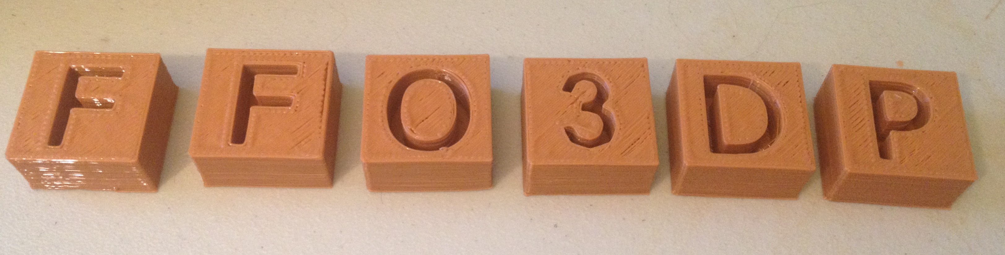
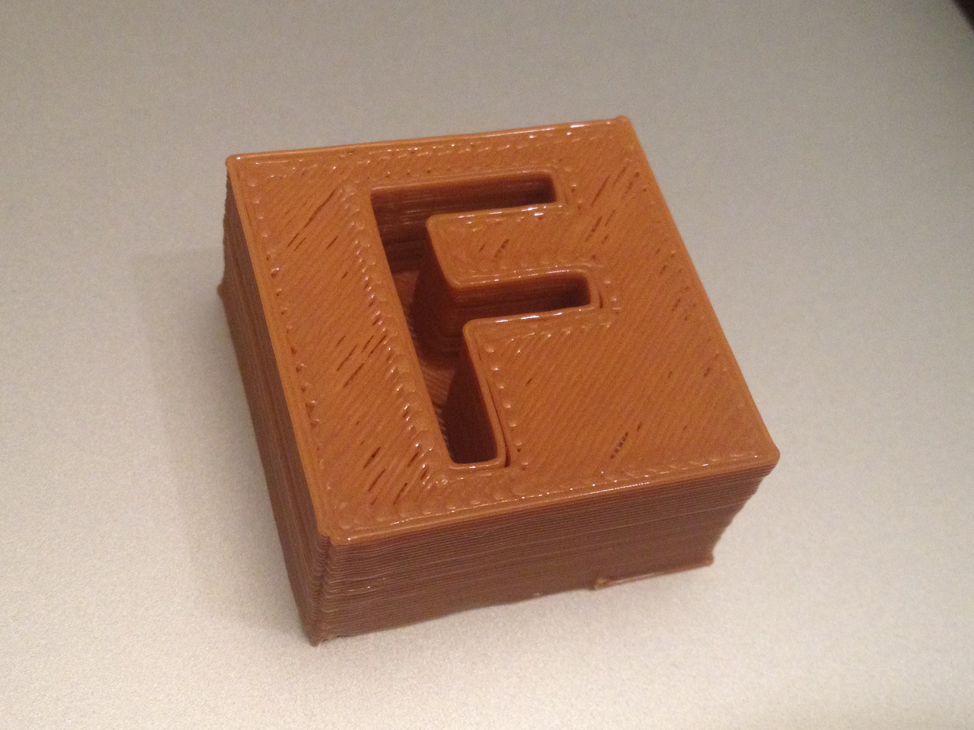
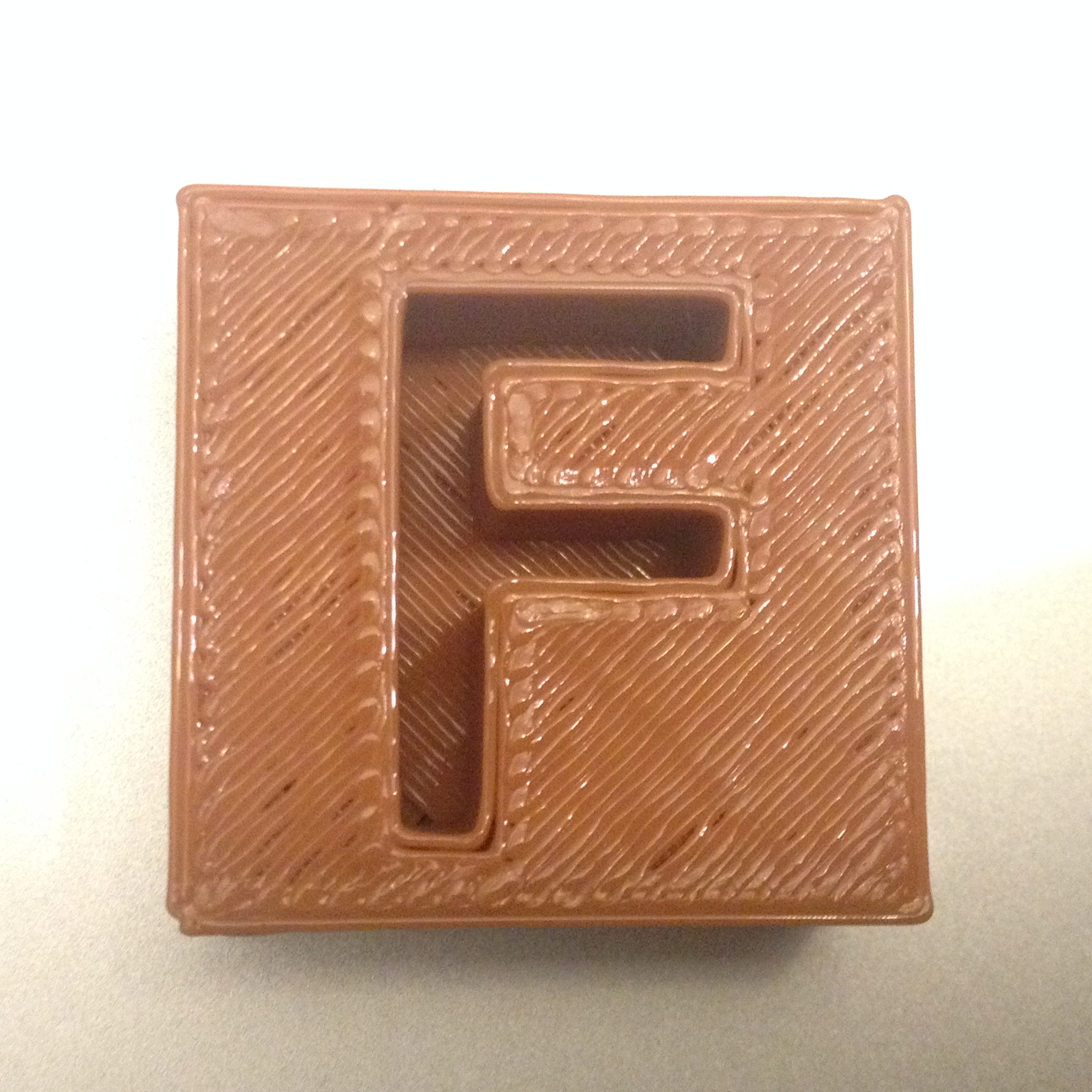
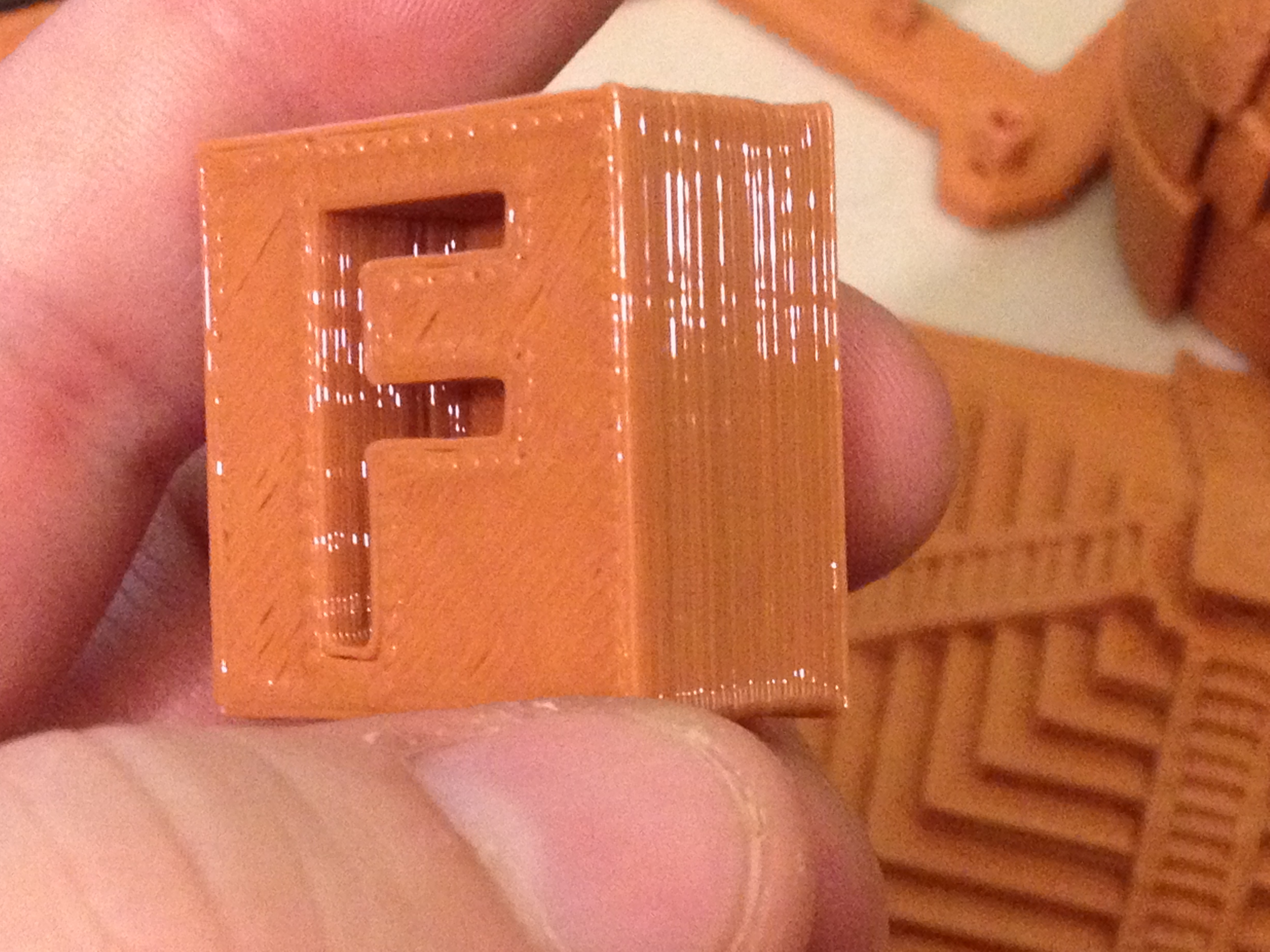
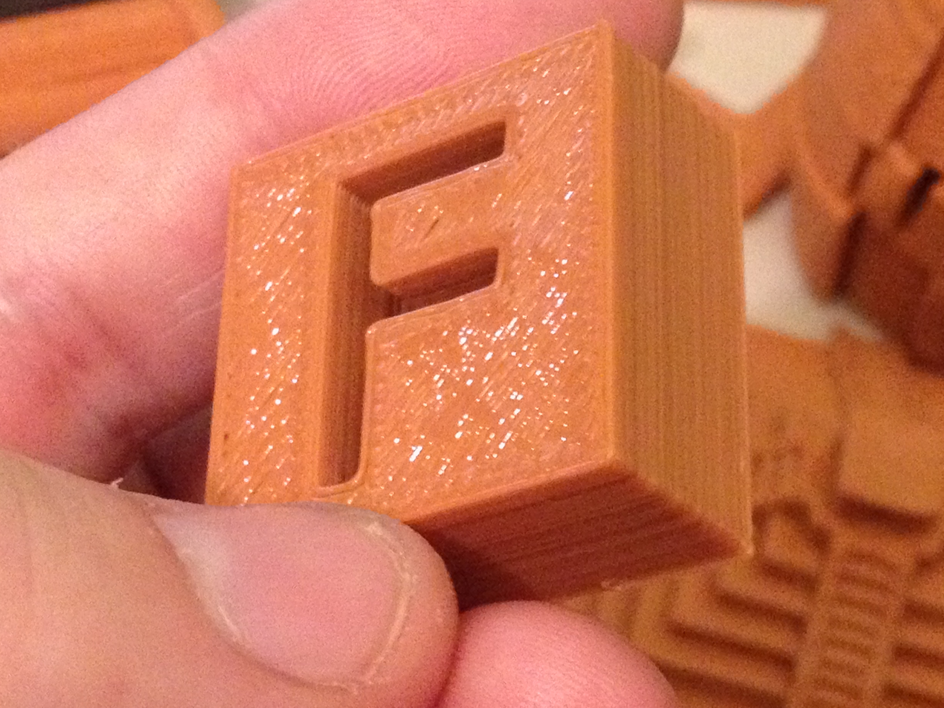
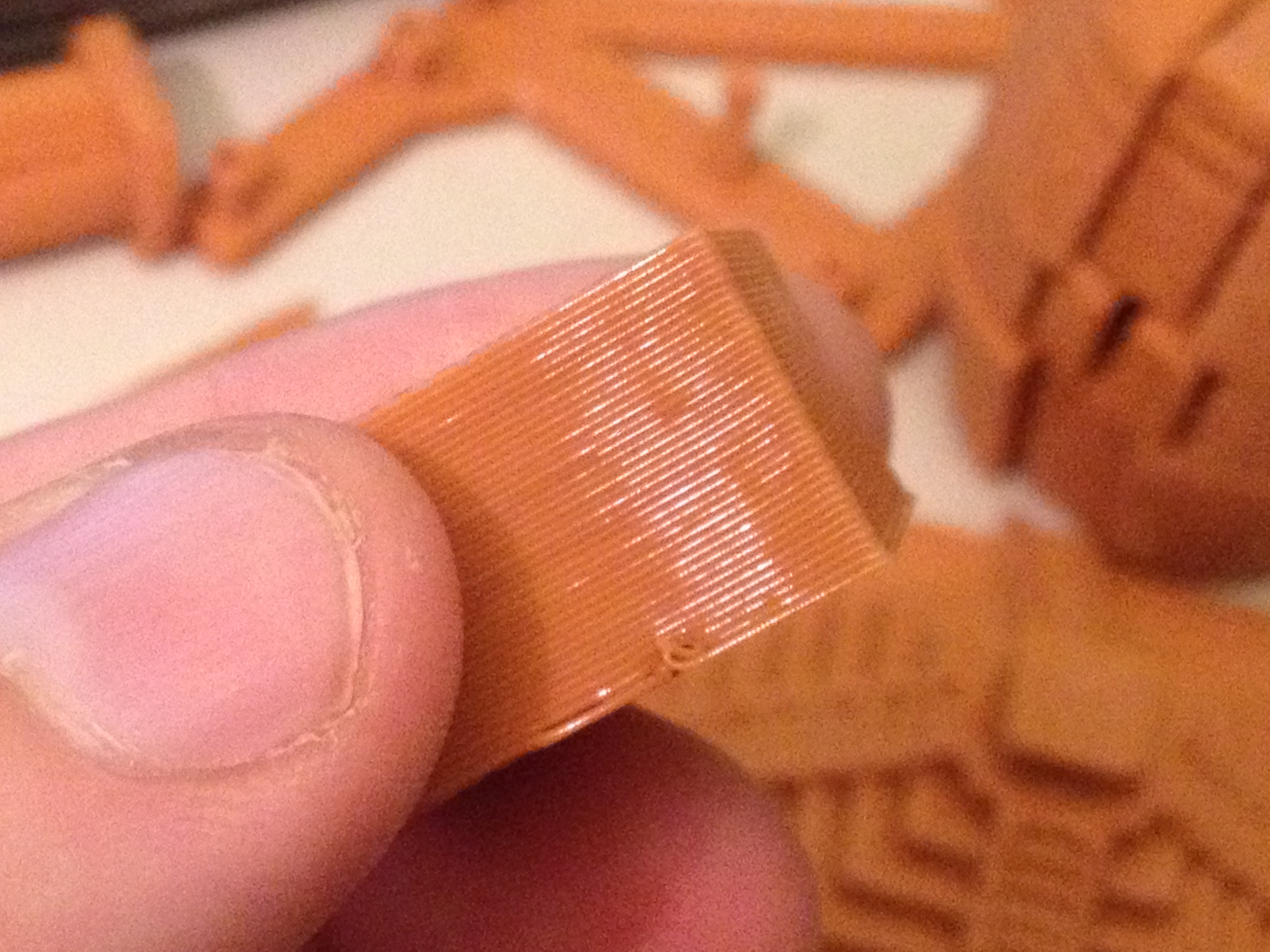
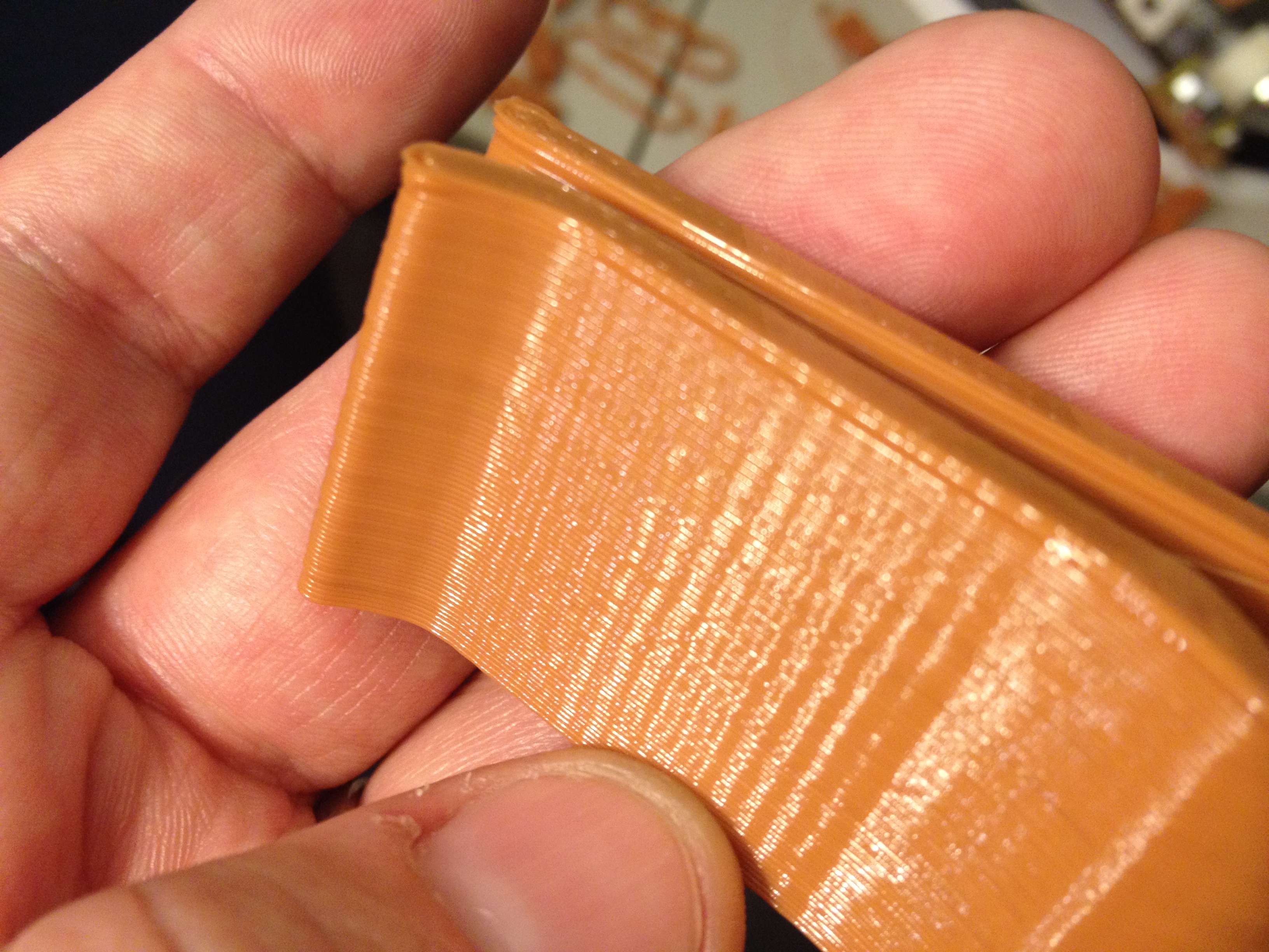
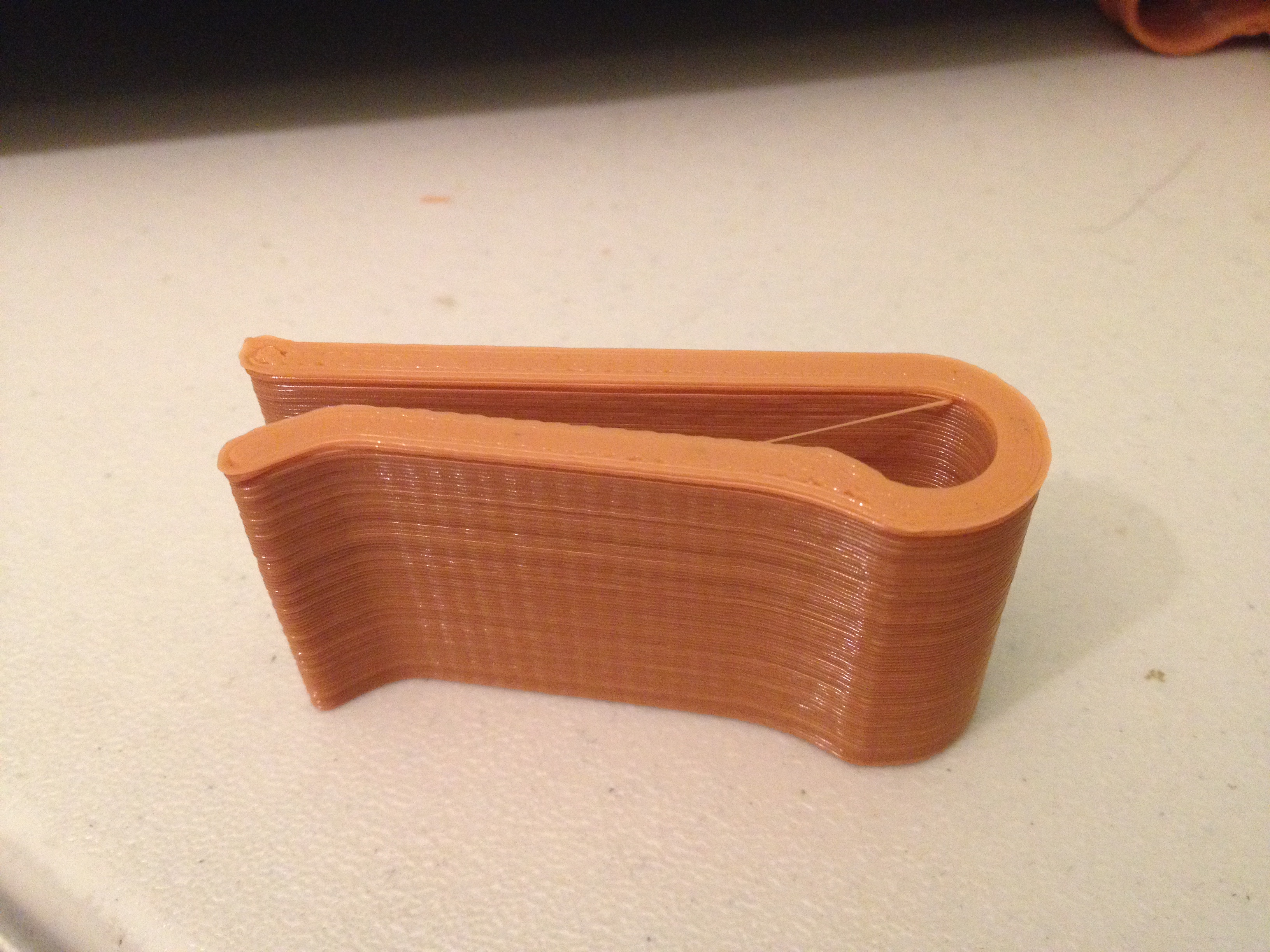
Since that had problems, I didn’t count it as my official part for February 9th. I made this “F”-block, which came out great:
These next pictures were an attempt to show how much this looked like caramel to me, and how much I wanted to be able to eat that block..
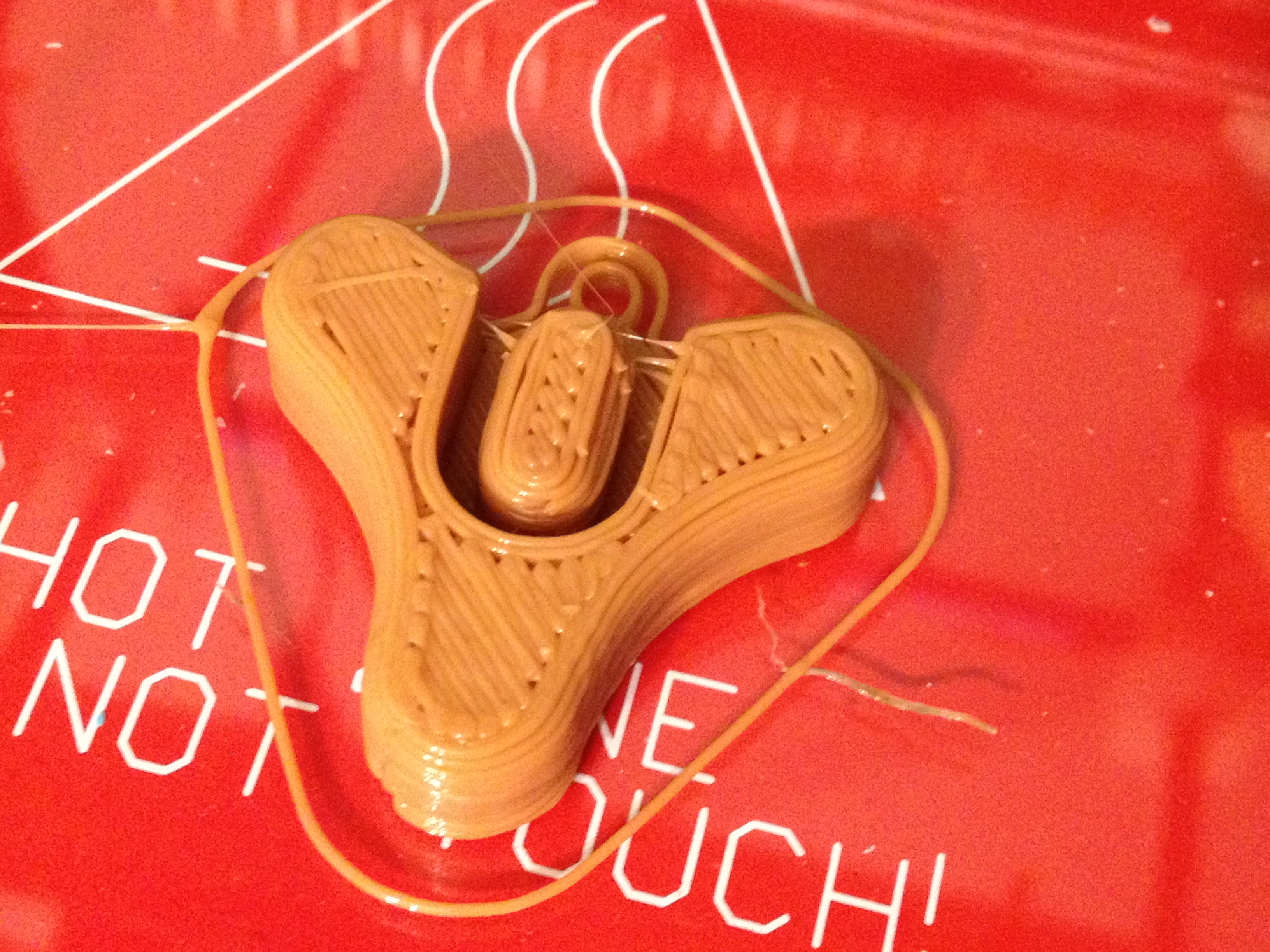
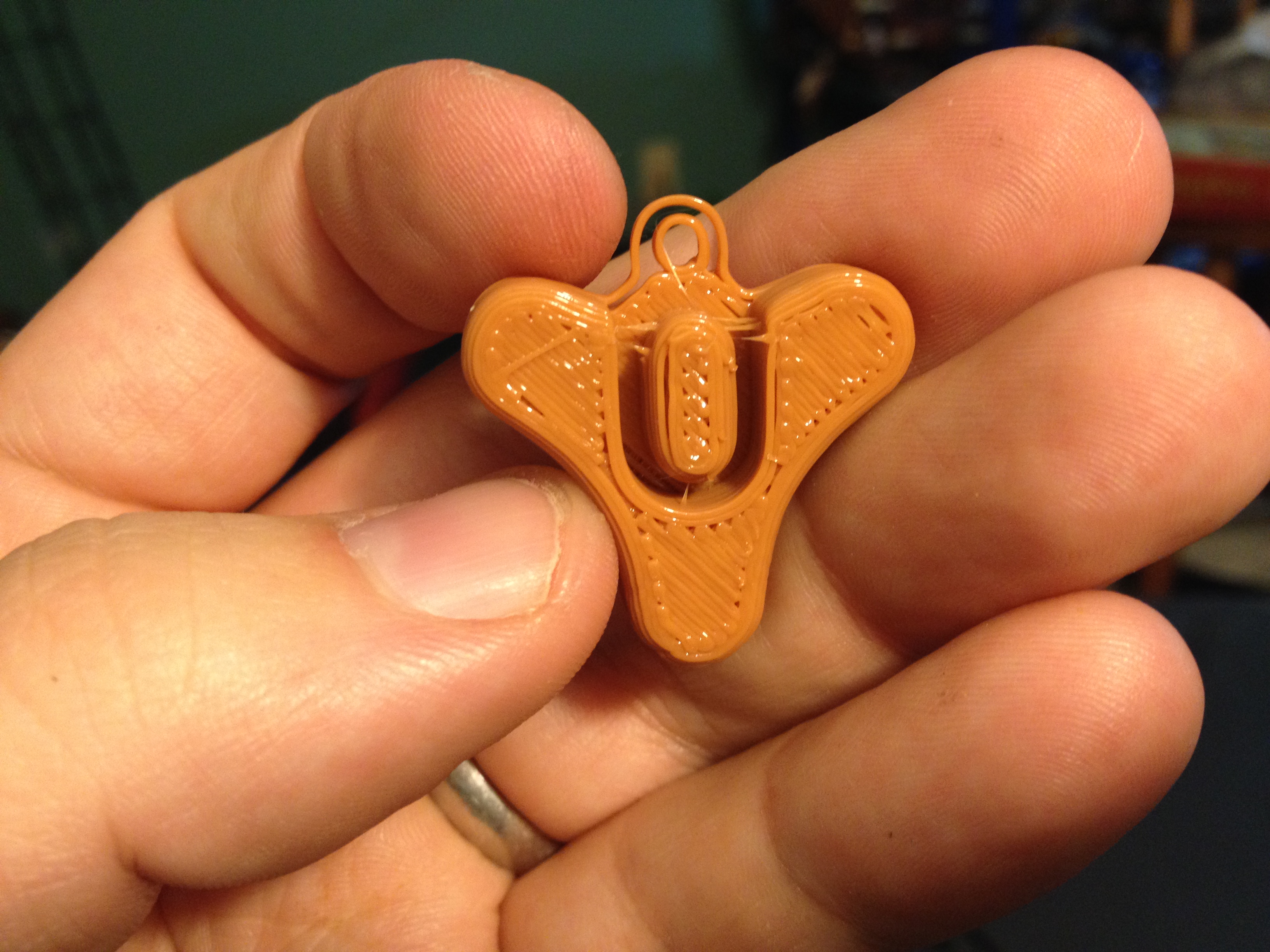
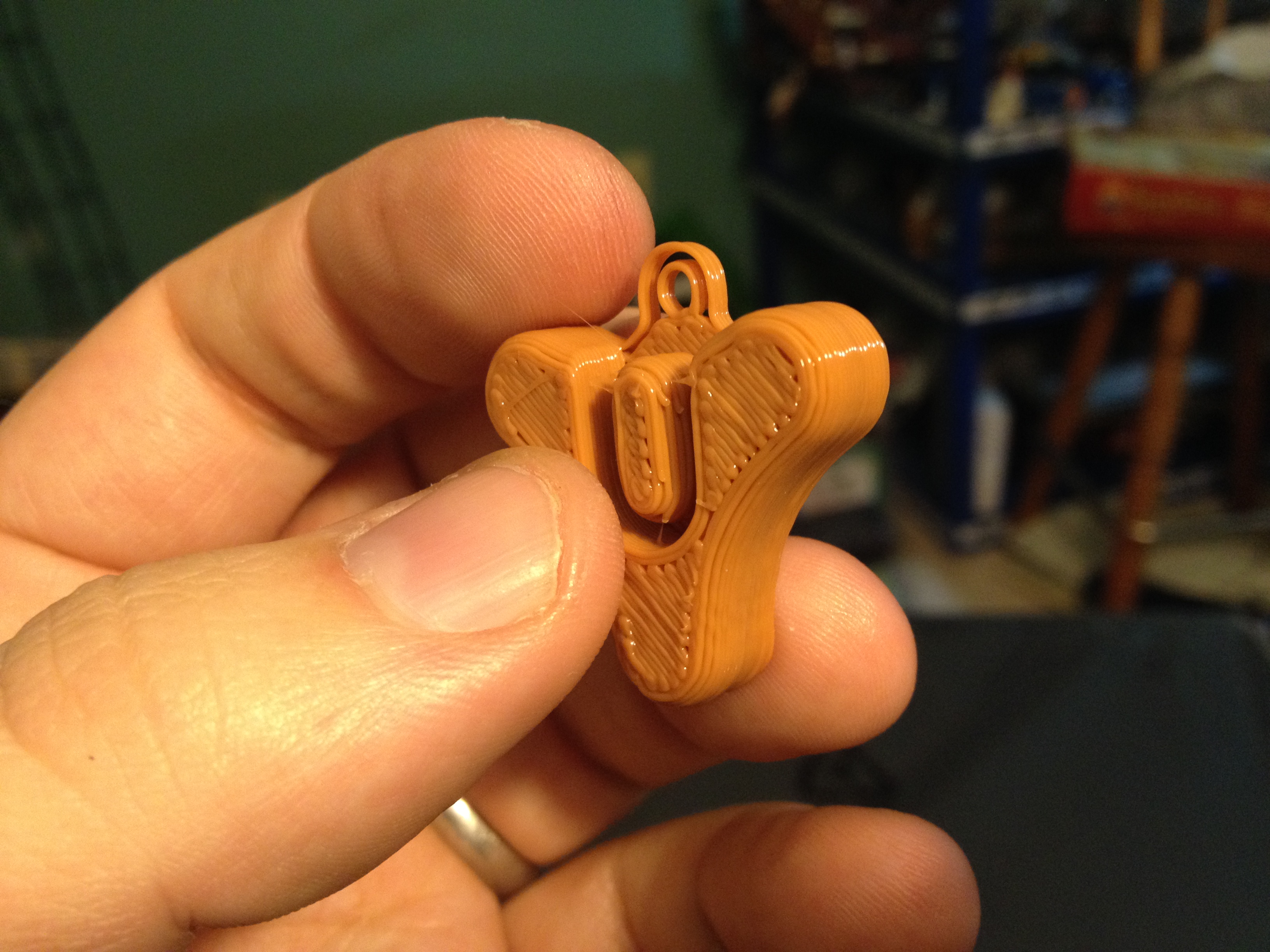
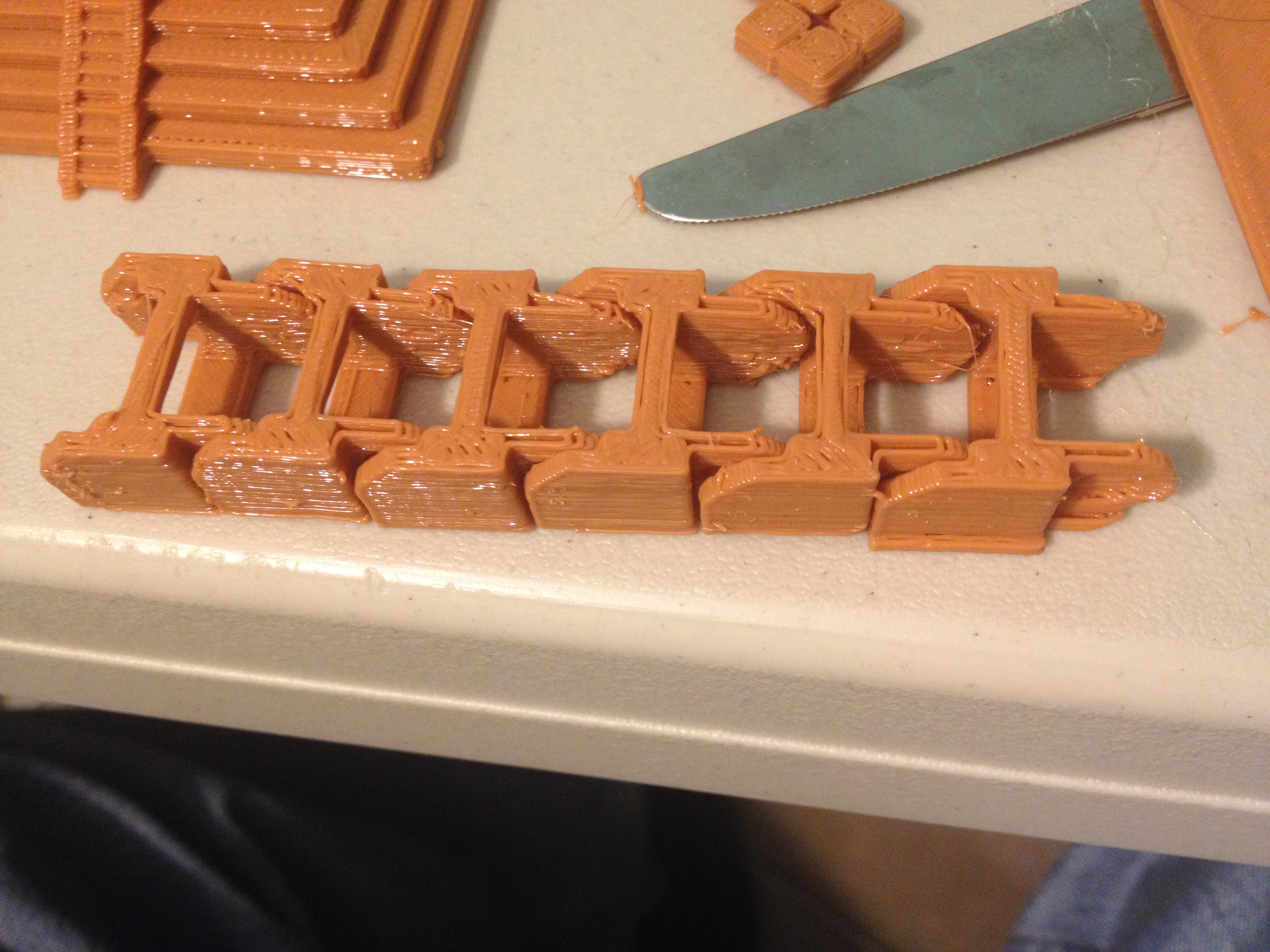
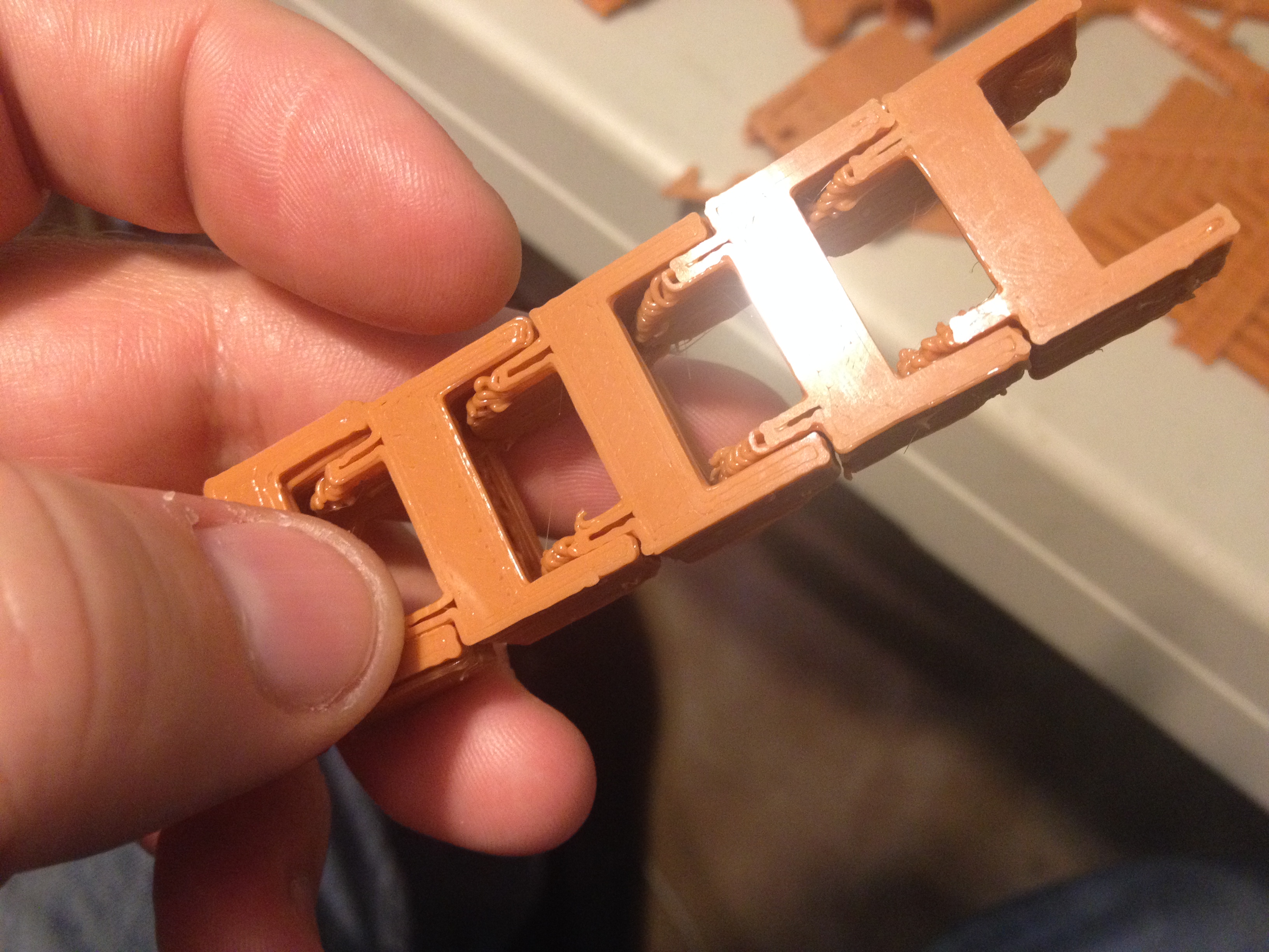
Bungie’s Game Destiny Pendant, Chain Mail – February 10, 2014
Back in February of 2014, it was much easier to do an entire February full of 3D prints, because Bungie had not yet released their incredible game Destiny (which has eaten up most of my spare time since September 2014!). They had, however, shown many copies of the logo for the game. Someone took it and made the Bungie’s Game Destiny Pendant object on thingiverse, which I printed on February 10th of 2014, before the rest of the world knew how awesome a game Destiny would become (I knew.. Love you Bungie!):
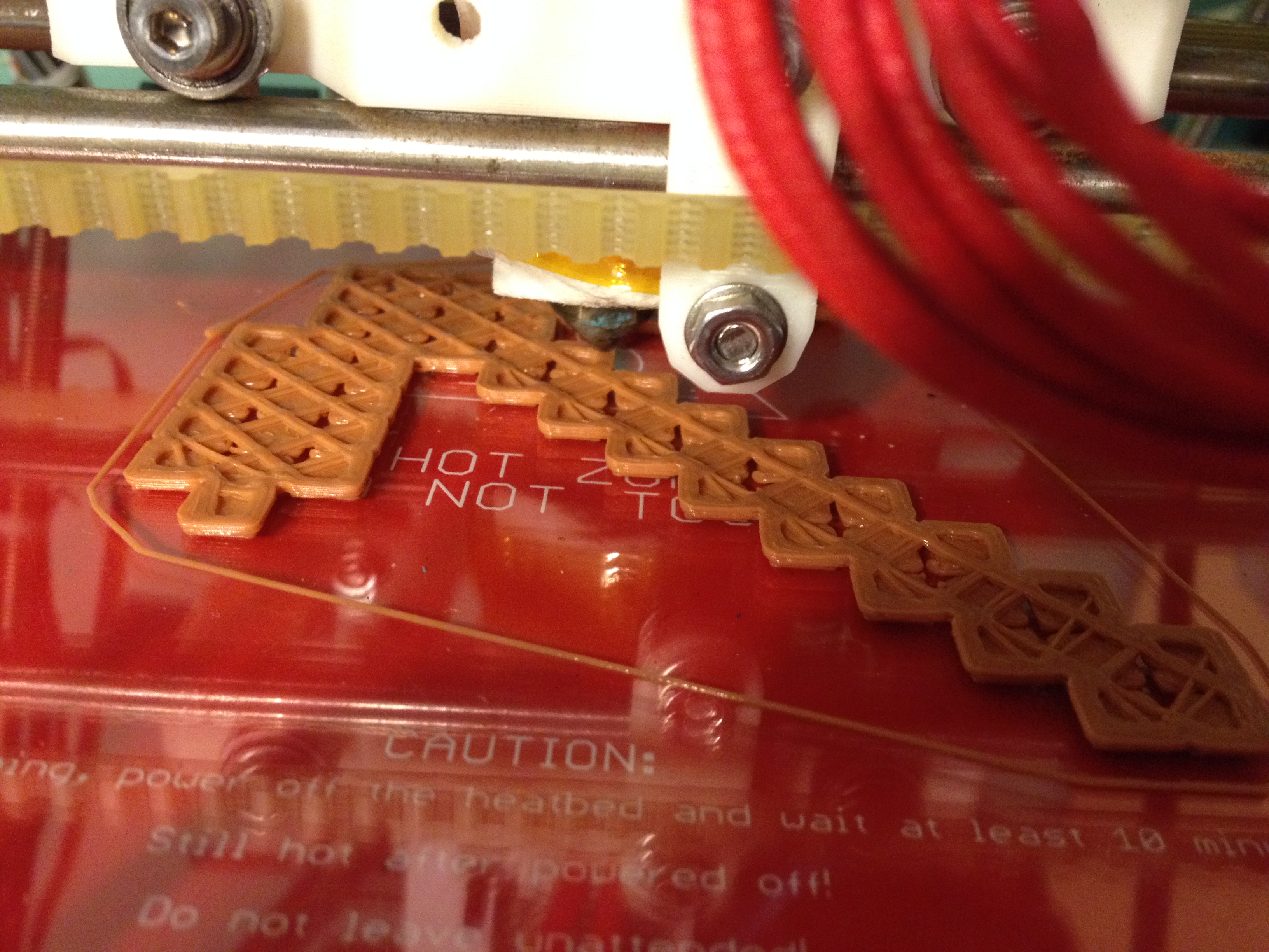
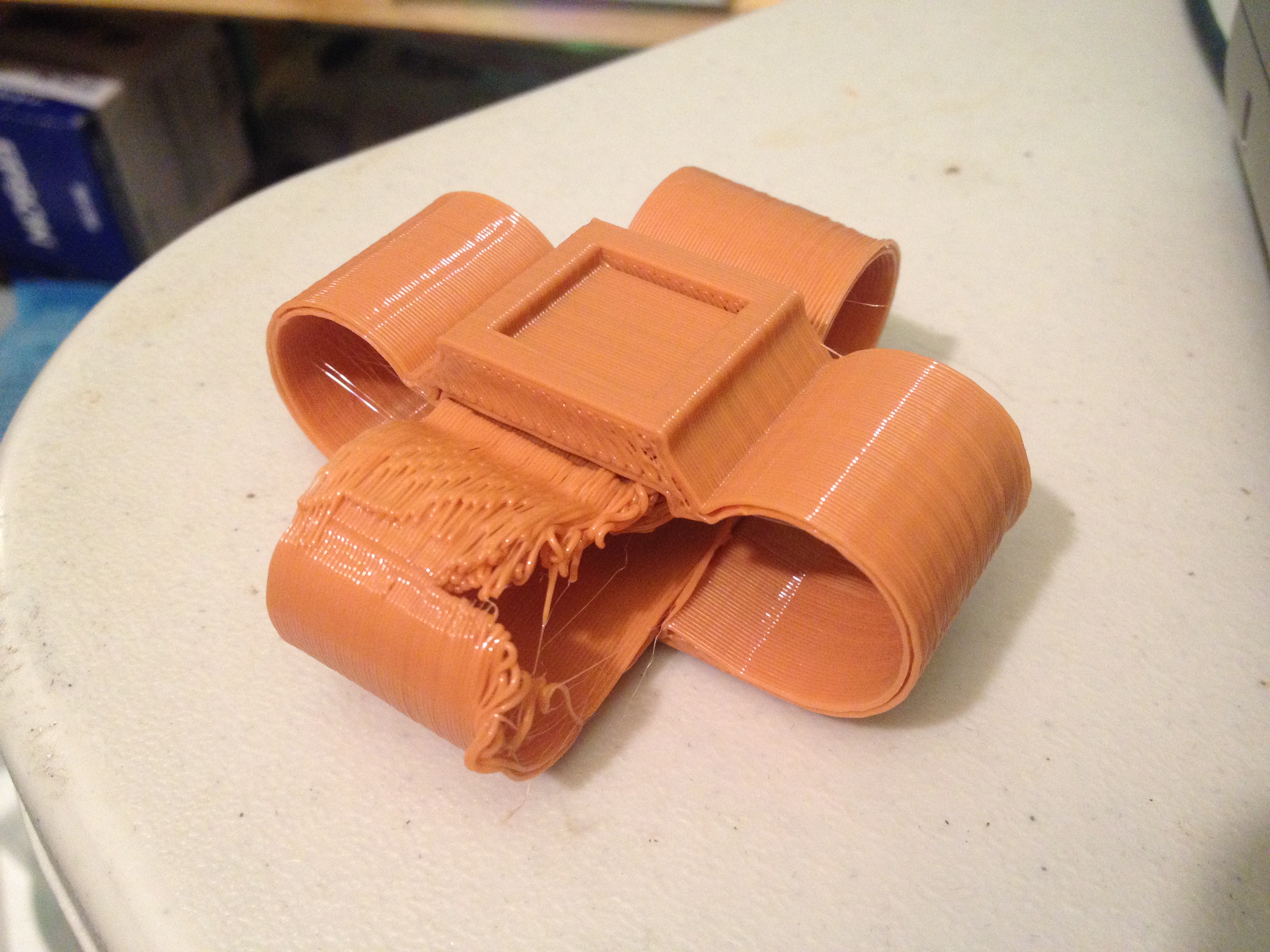
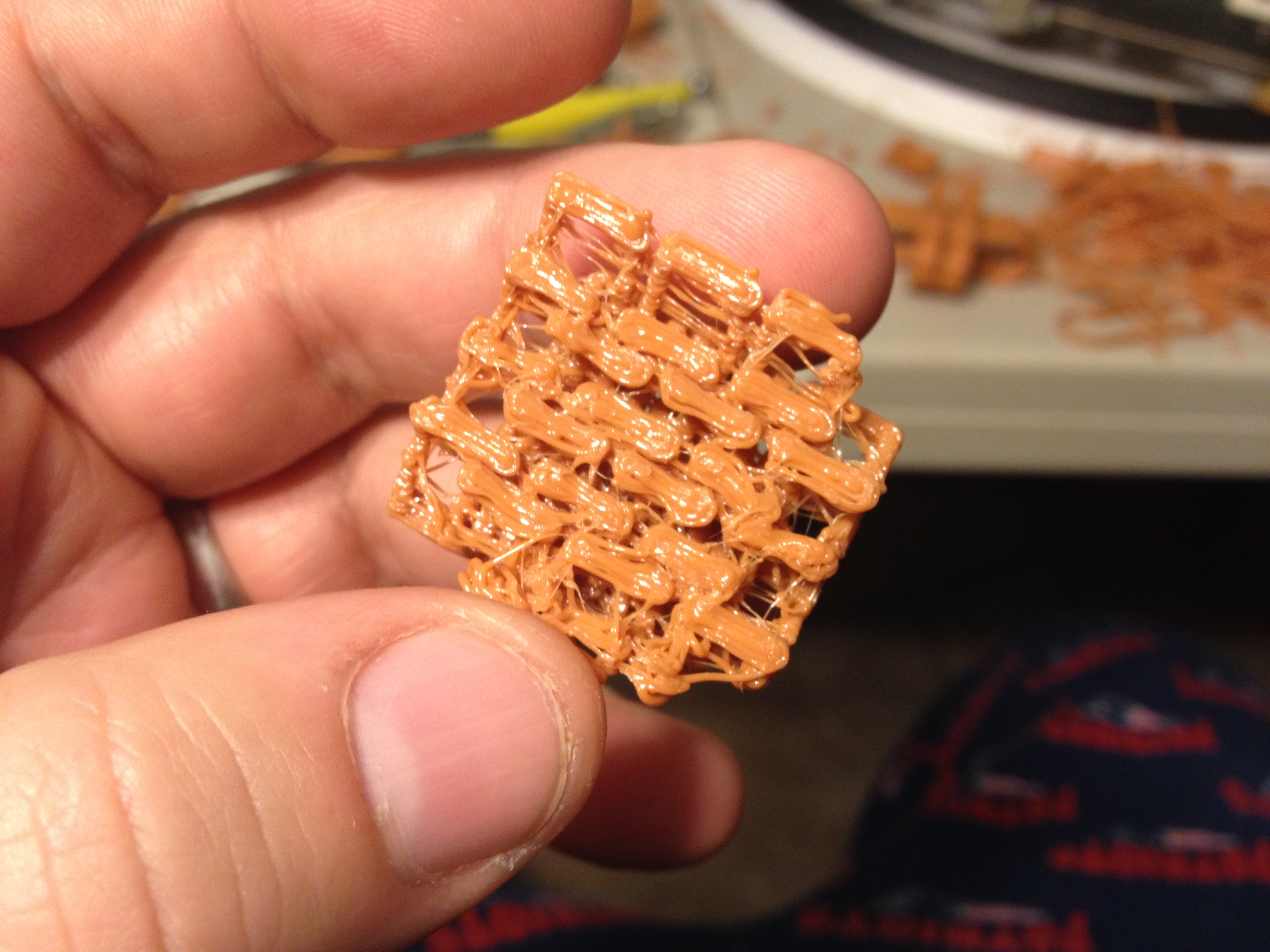
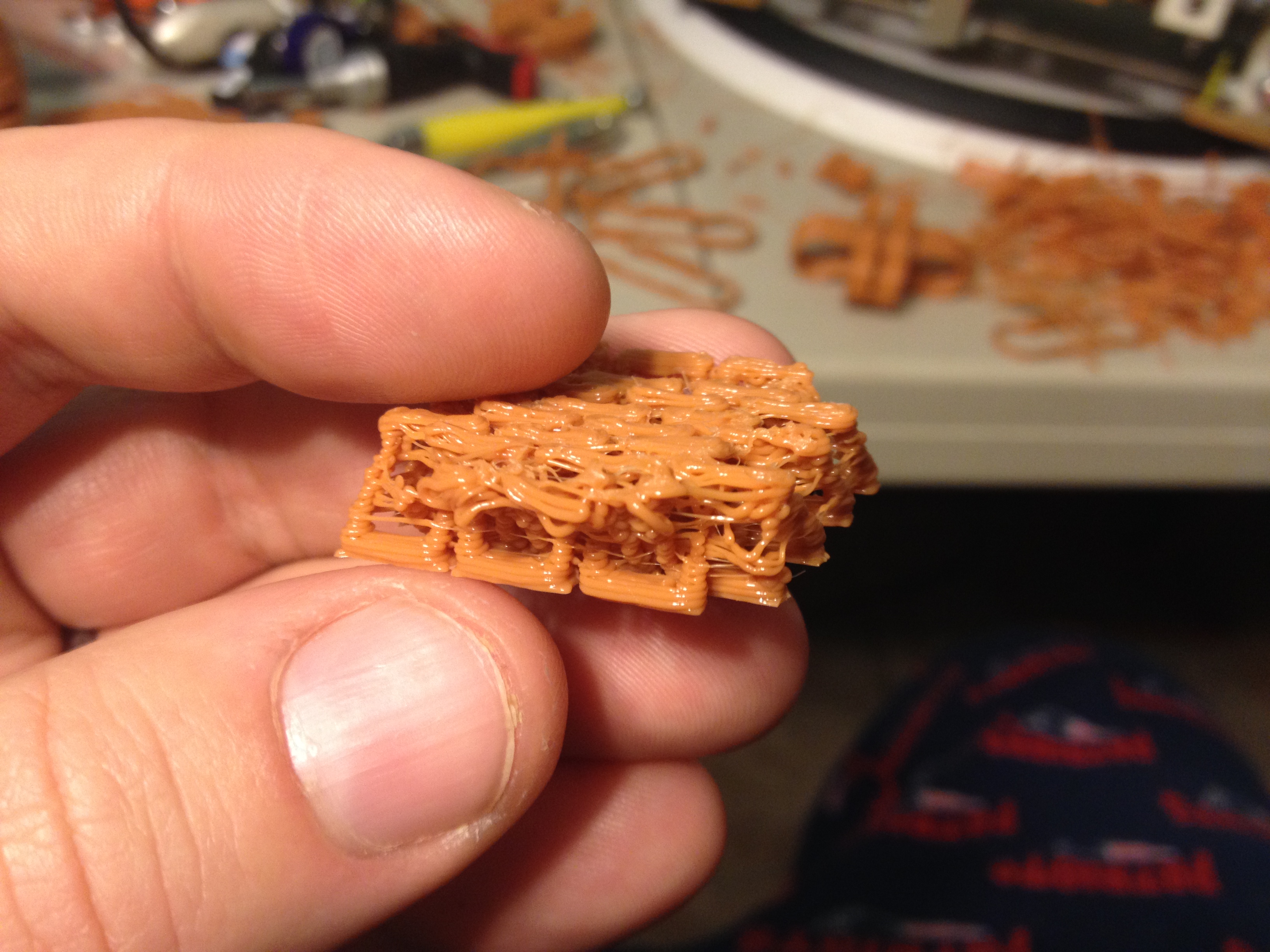
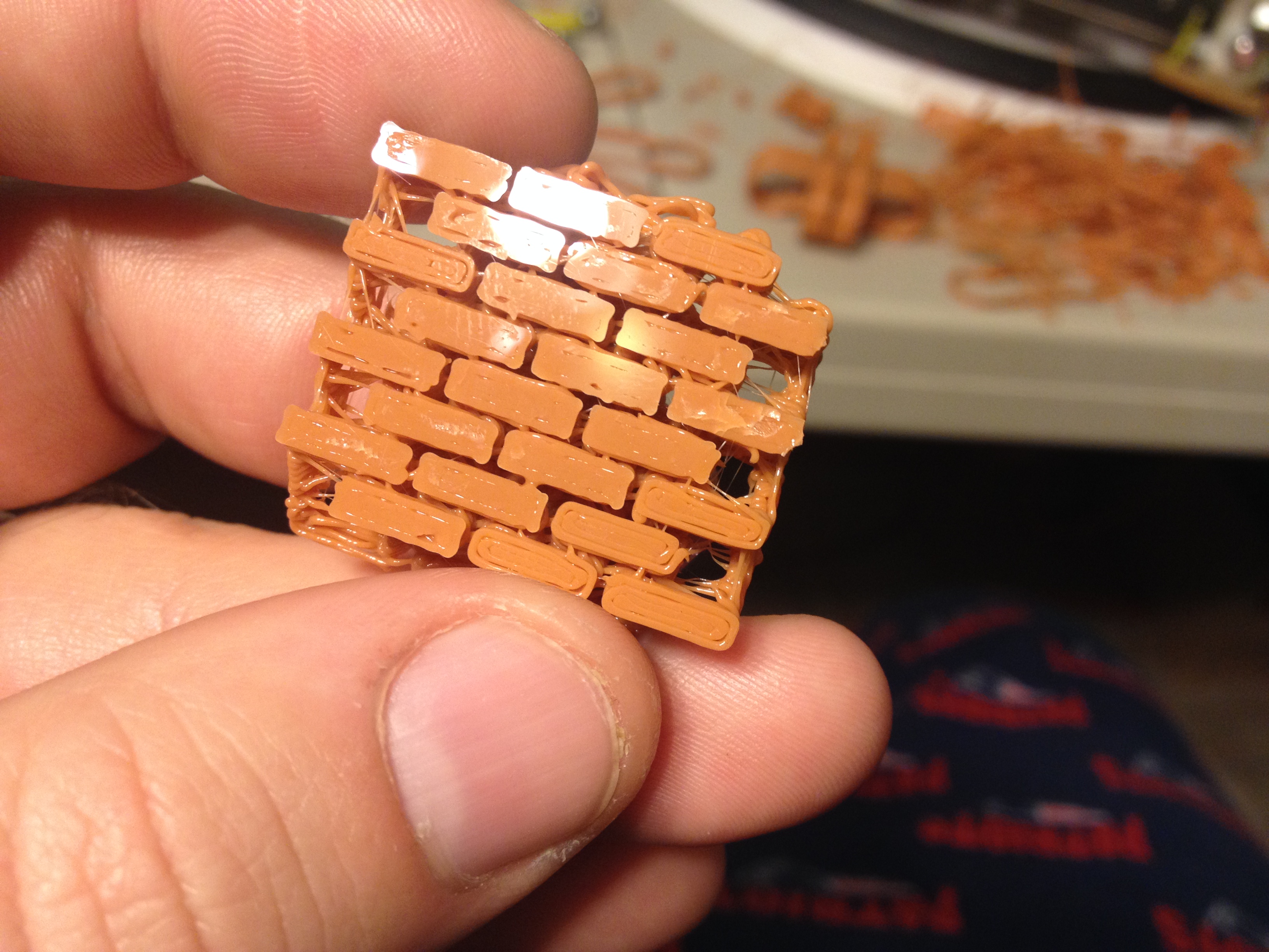
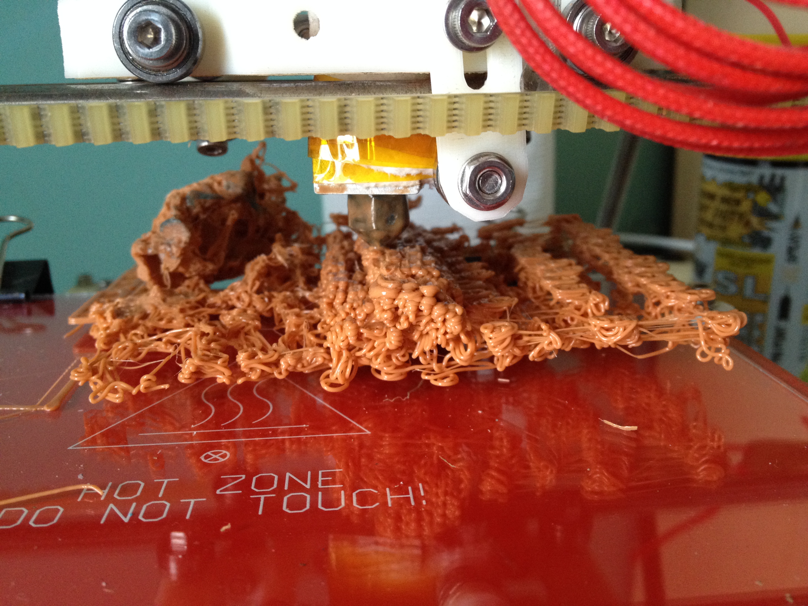
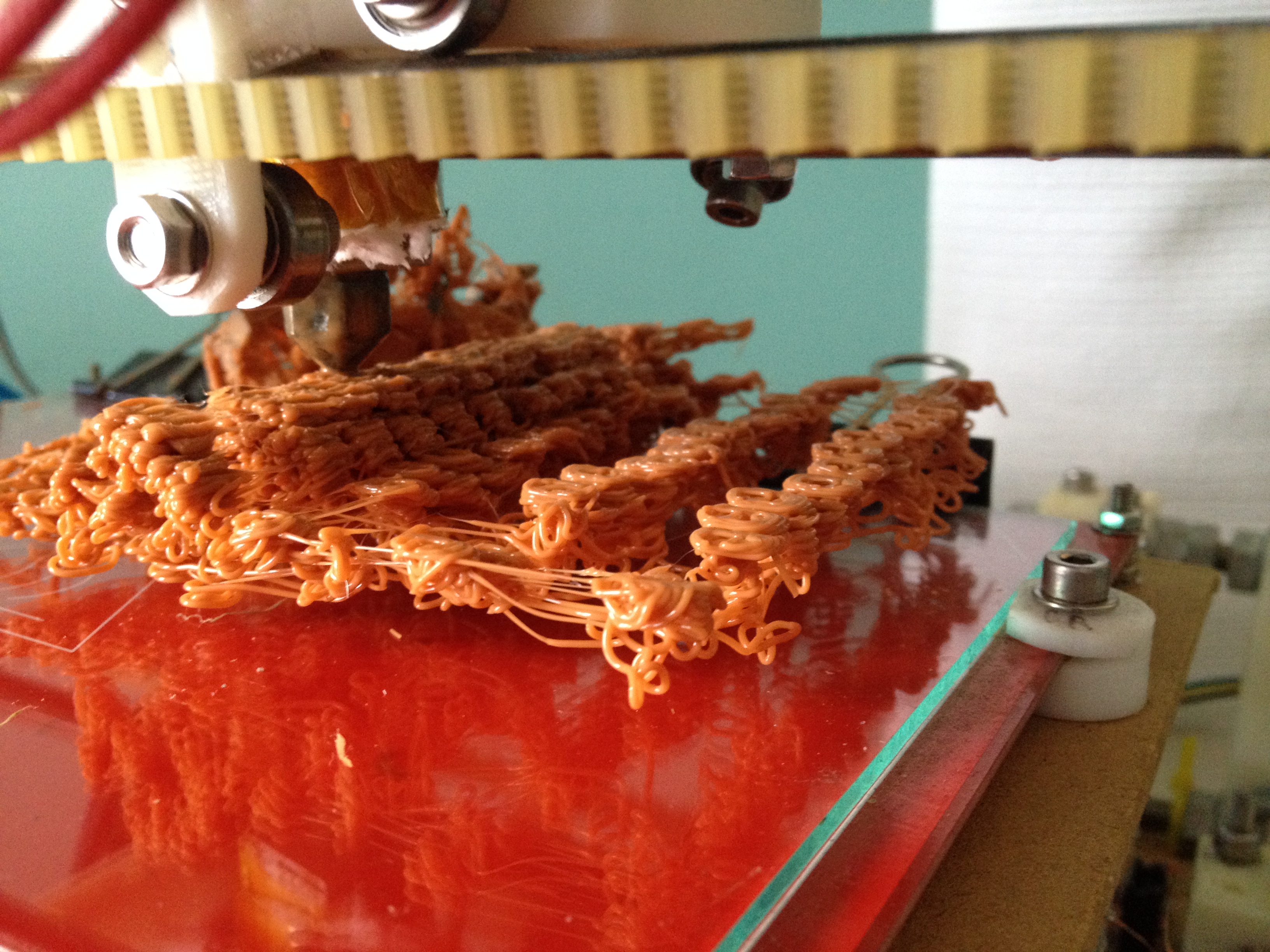
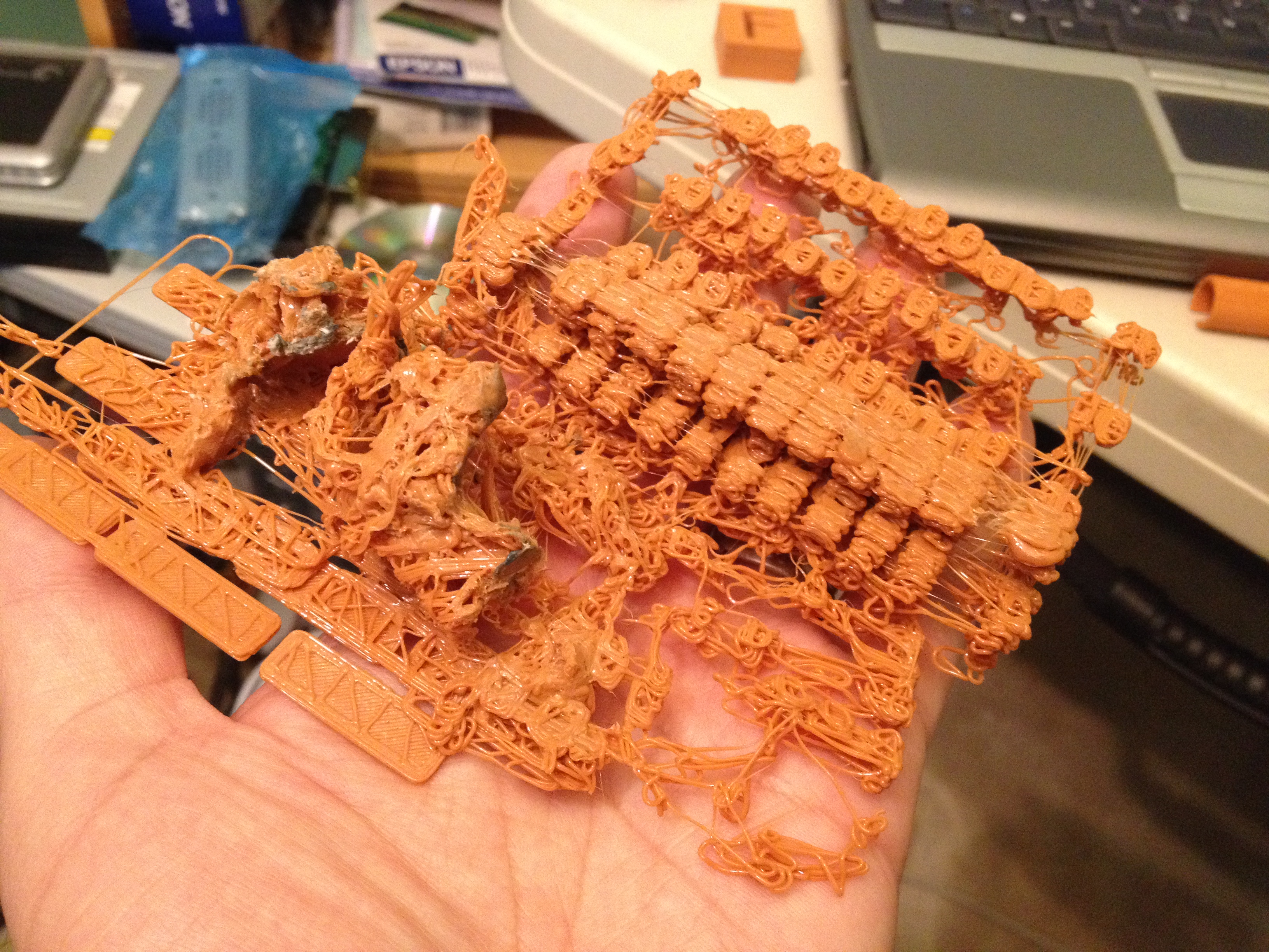
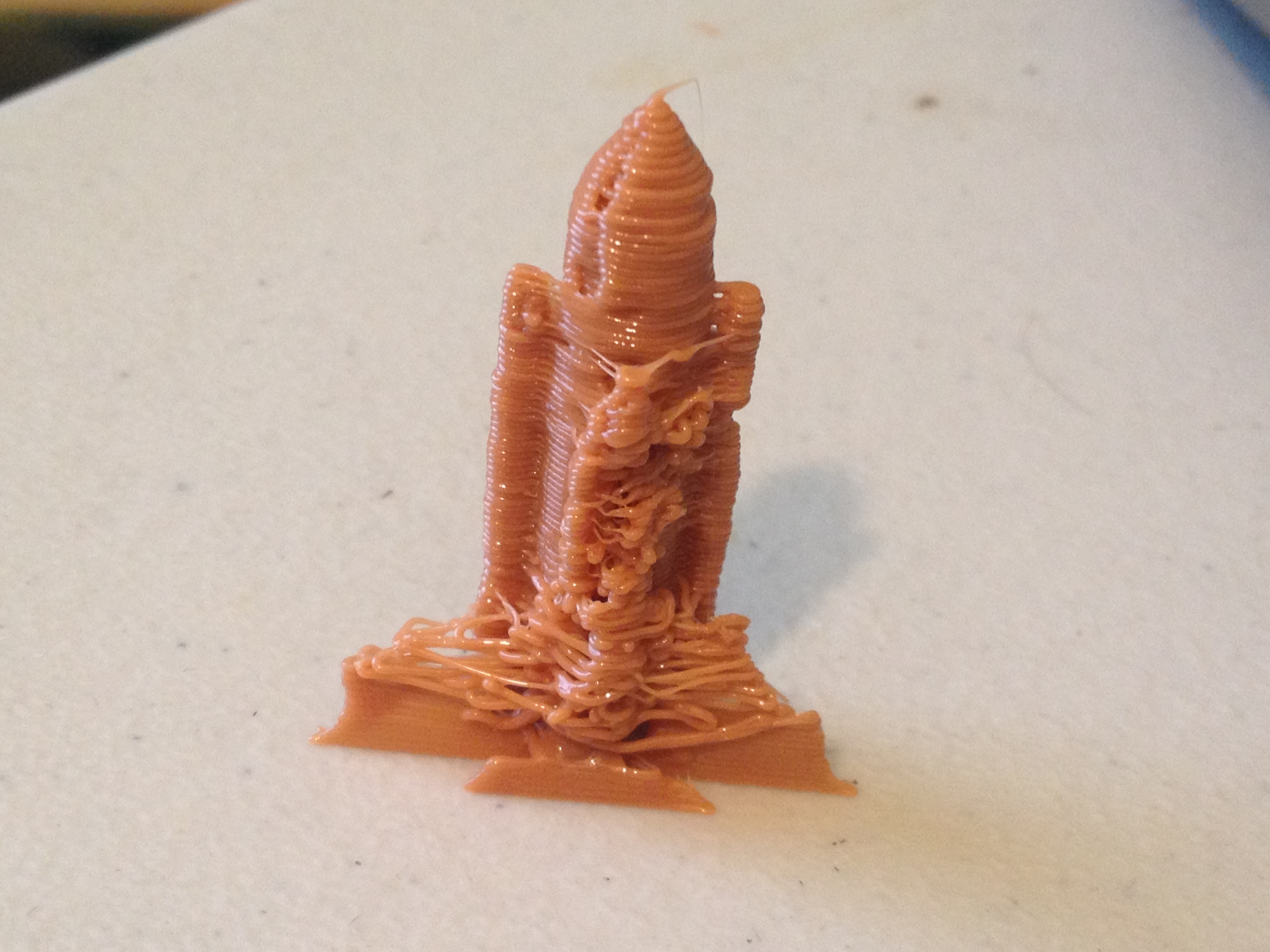
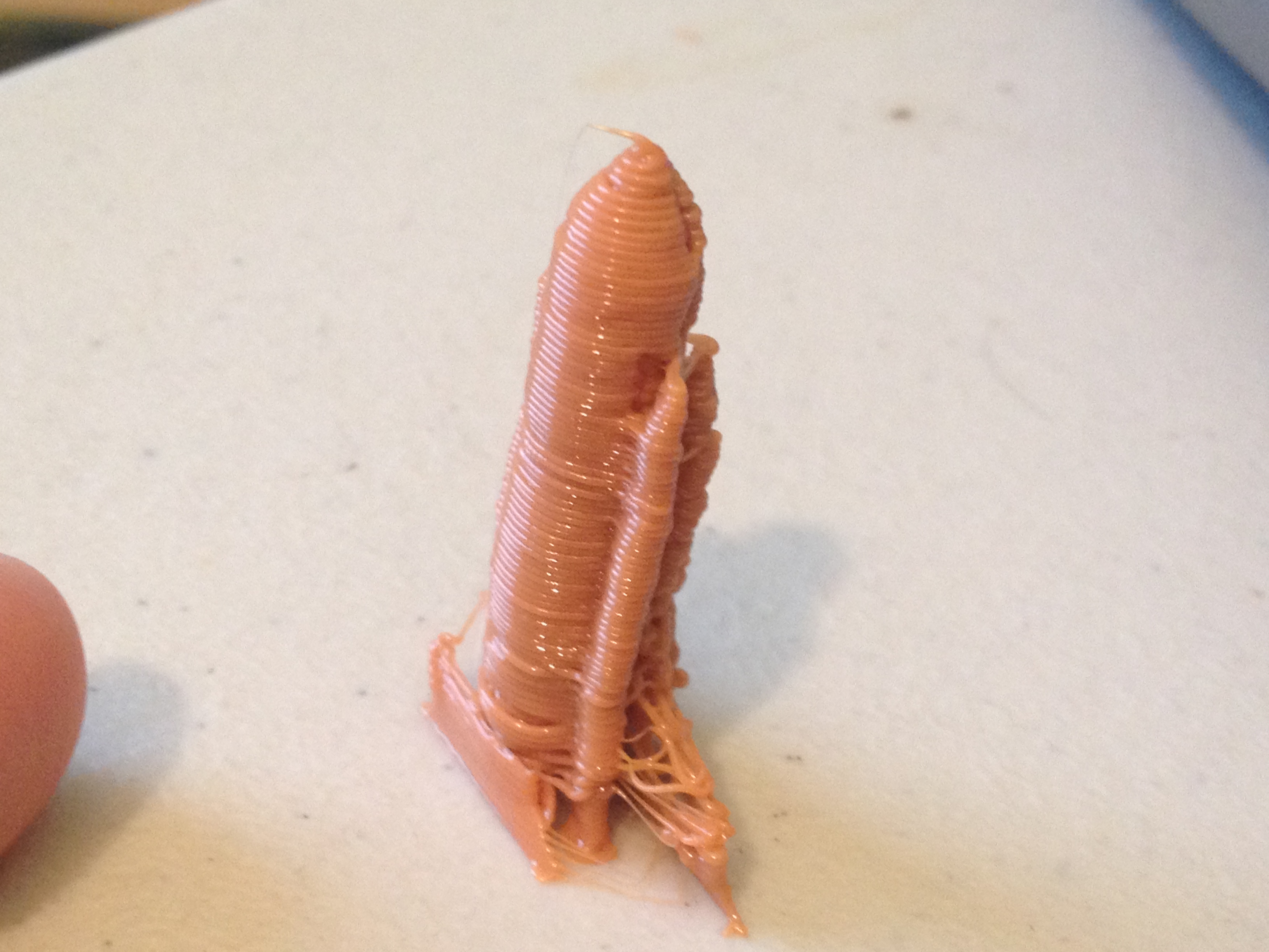
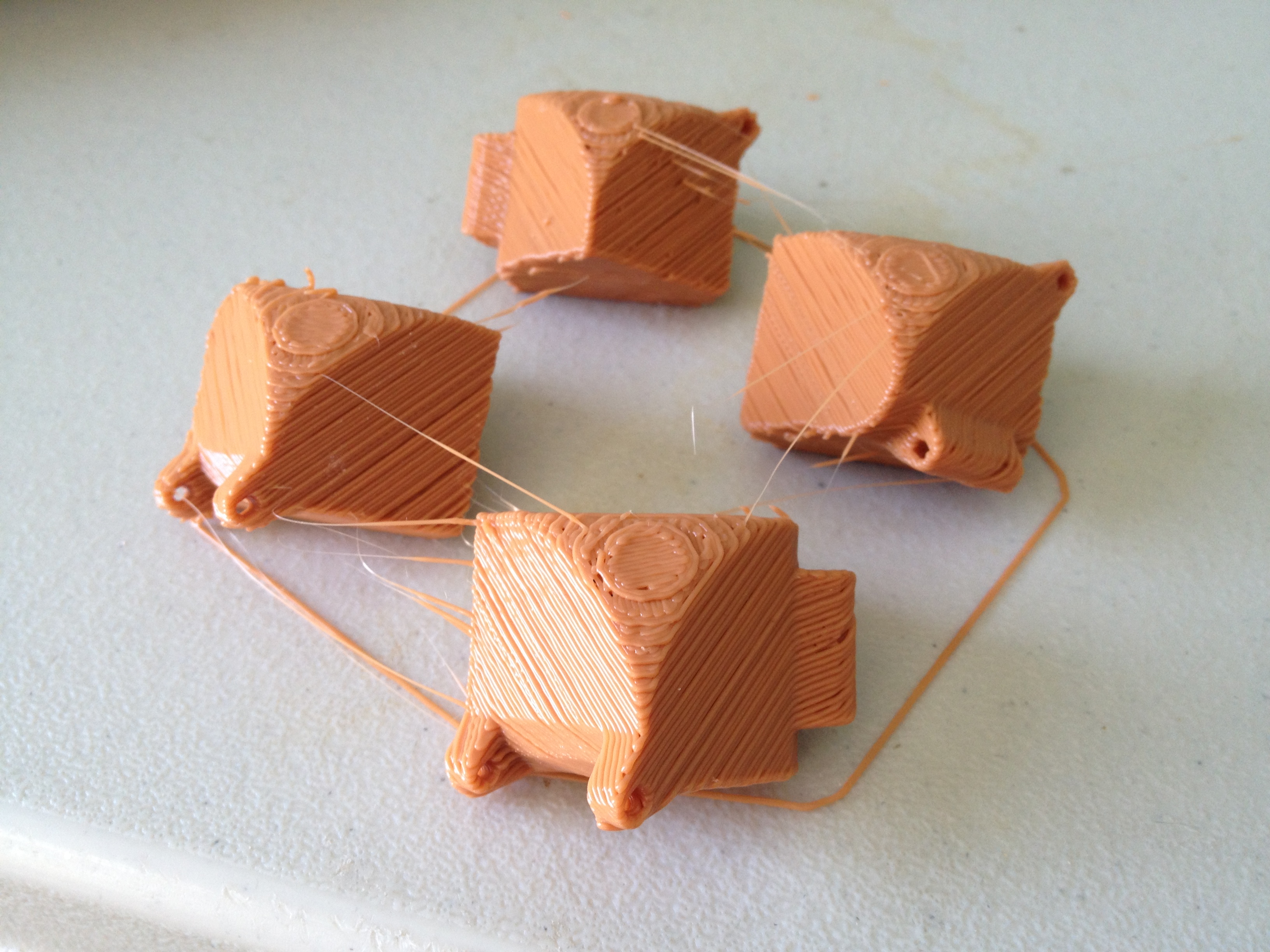
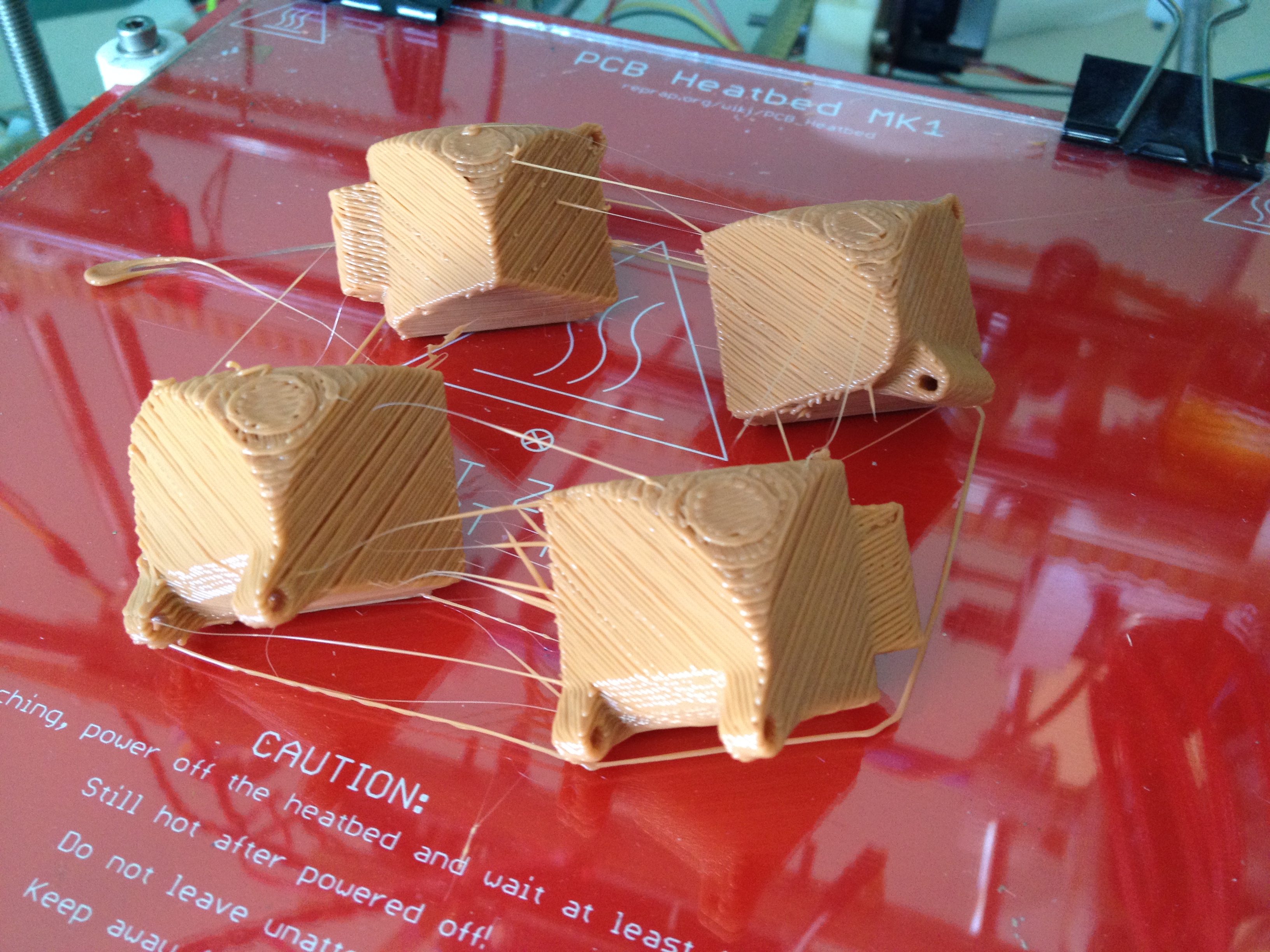
Before printing that, I had attempted to print some Chainmail.. That didn’t go so well. I tried printing out a small version, which fused together and broke apart when I tried to bend it. Then I tried scaling it up, and left that print unattended for too long. Feast your eyes on some failures:
So like I said, I scaled it up, and left the printing unattended…
Like I said, the official part for the day was the Bungie pendant. 🙂
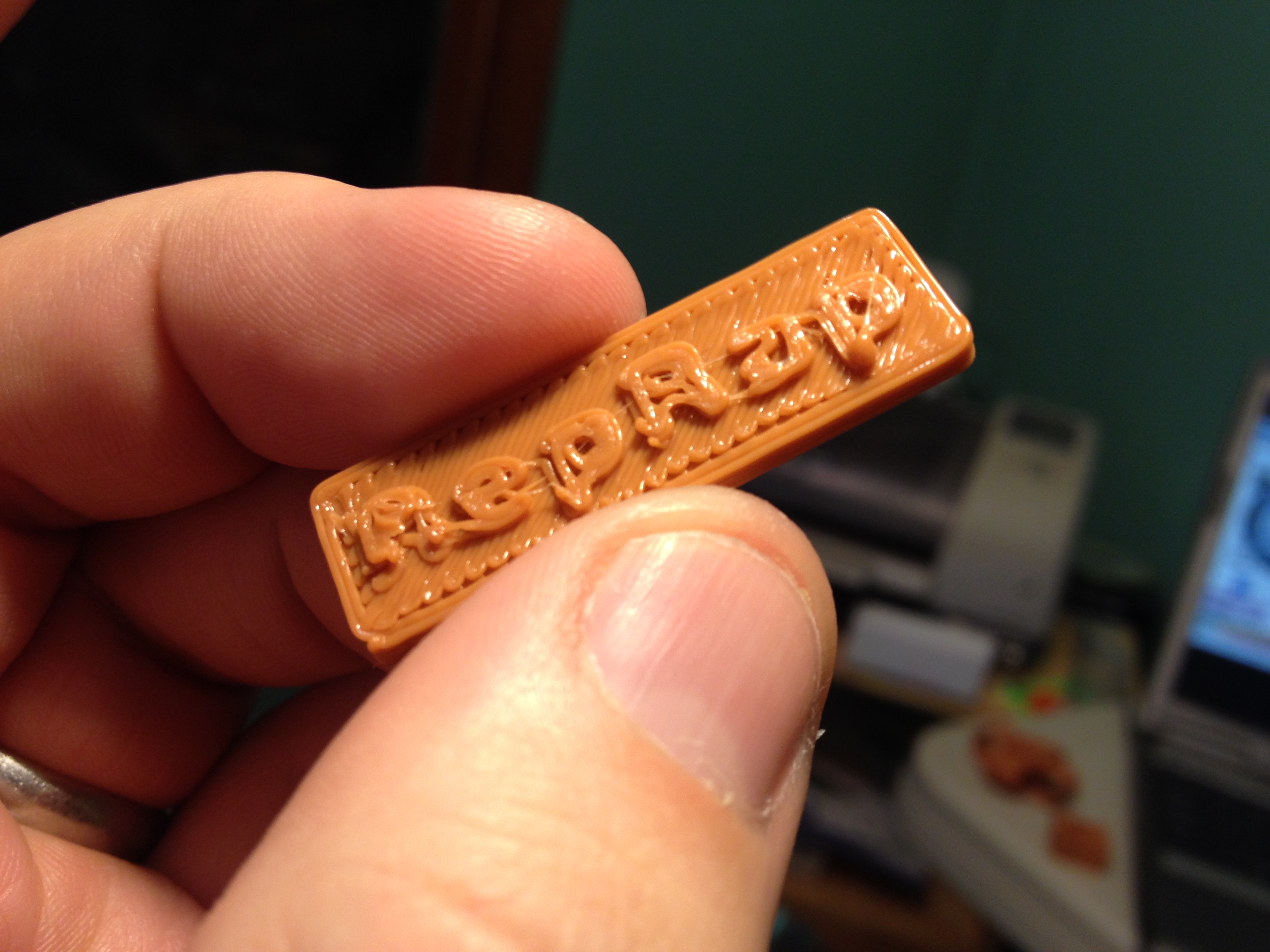
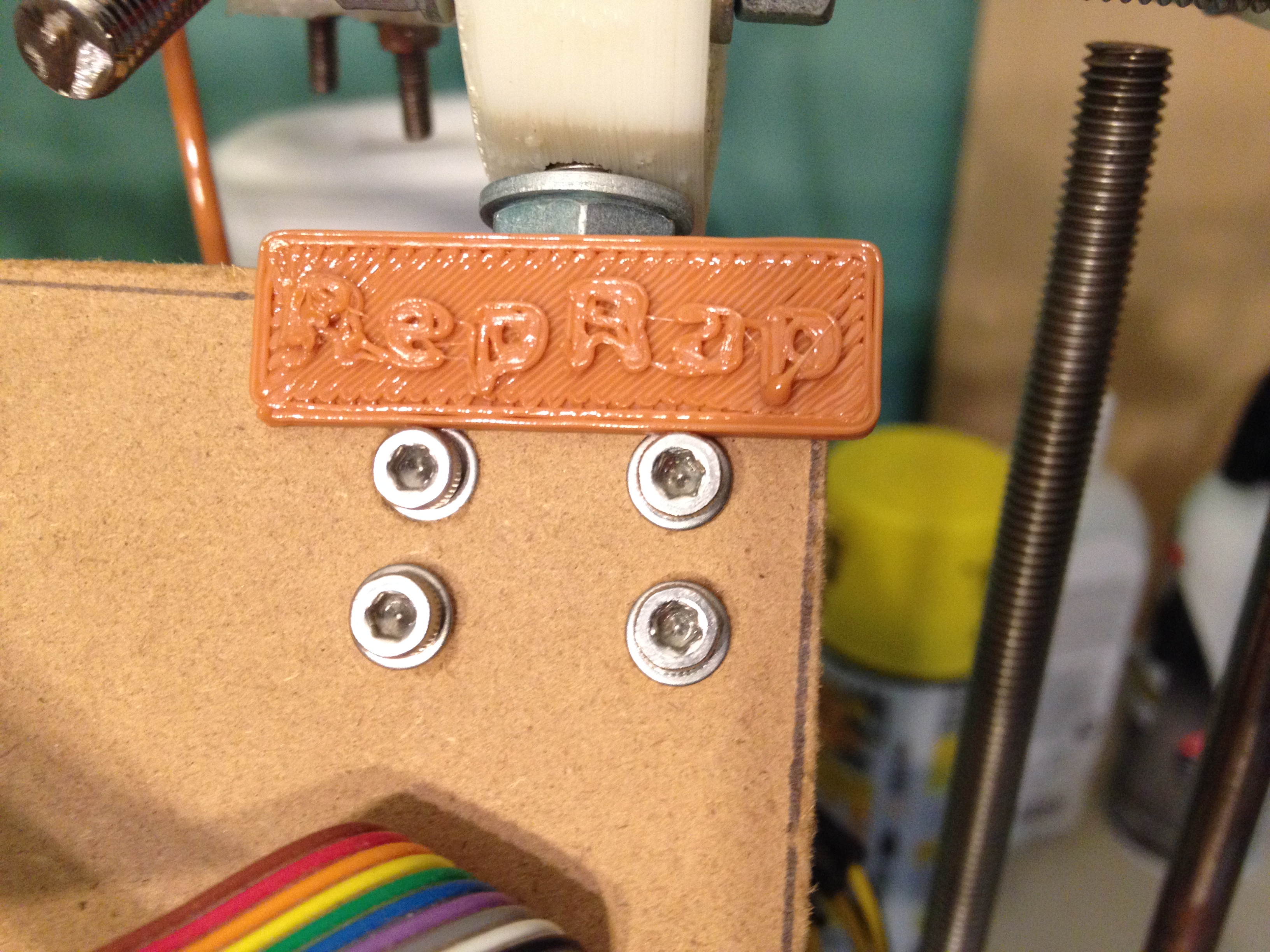
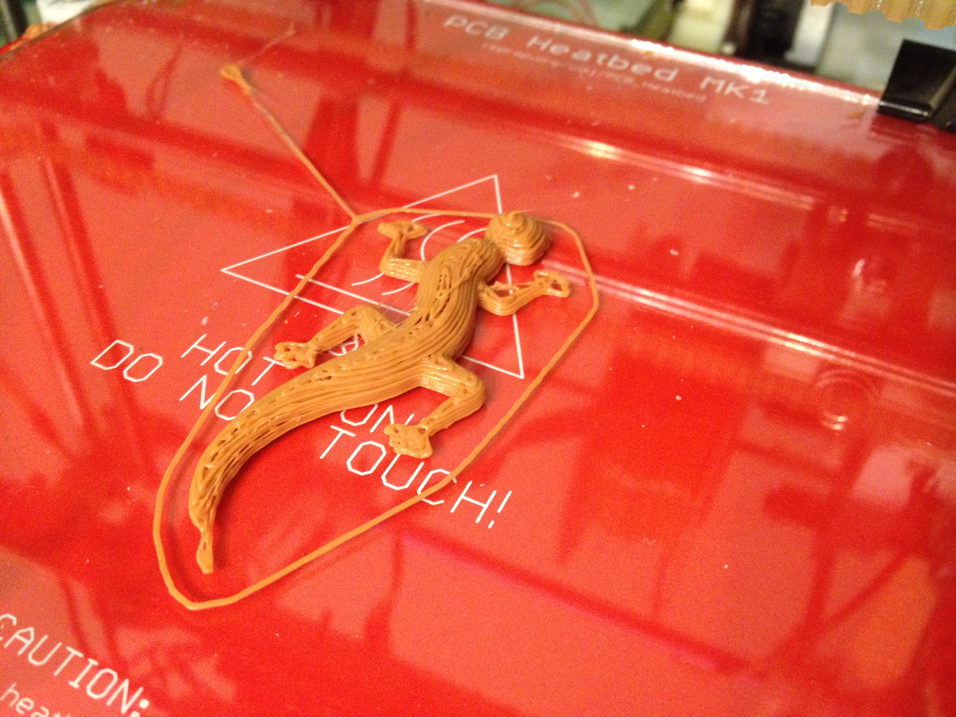
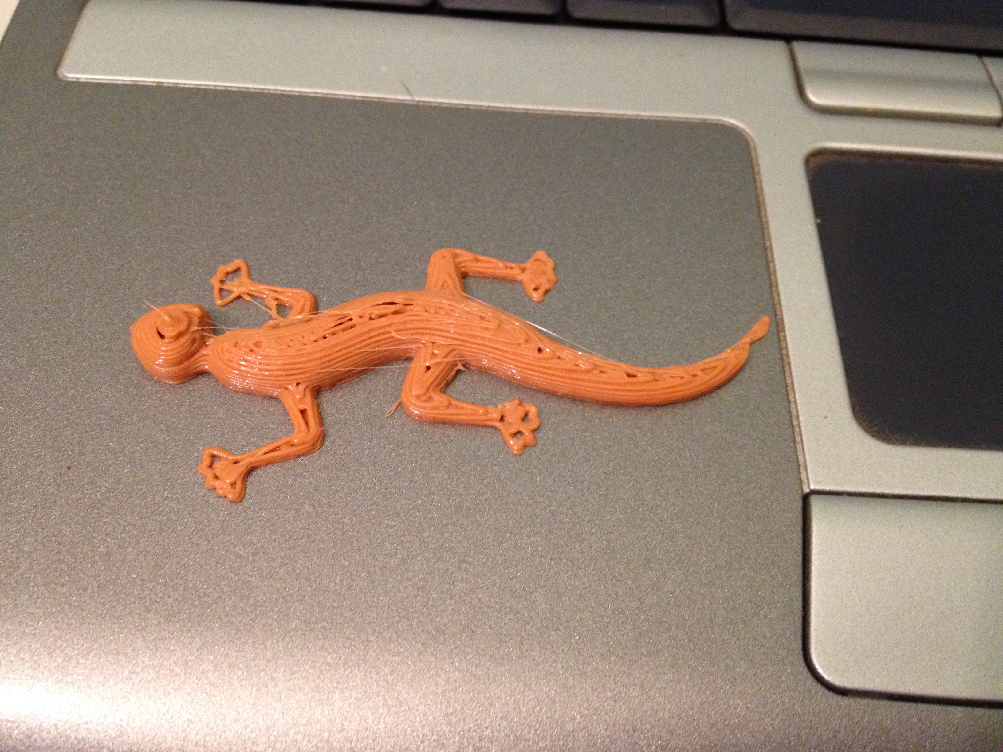
RepRap Name tab, A Gekko – Fixed, Simplified, and Plated – February 11, 2014
Over the next several days, if I finished my print for the day, I’d start up another 4 links of the chain, just to make it larger.
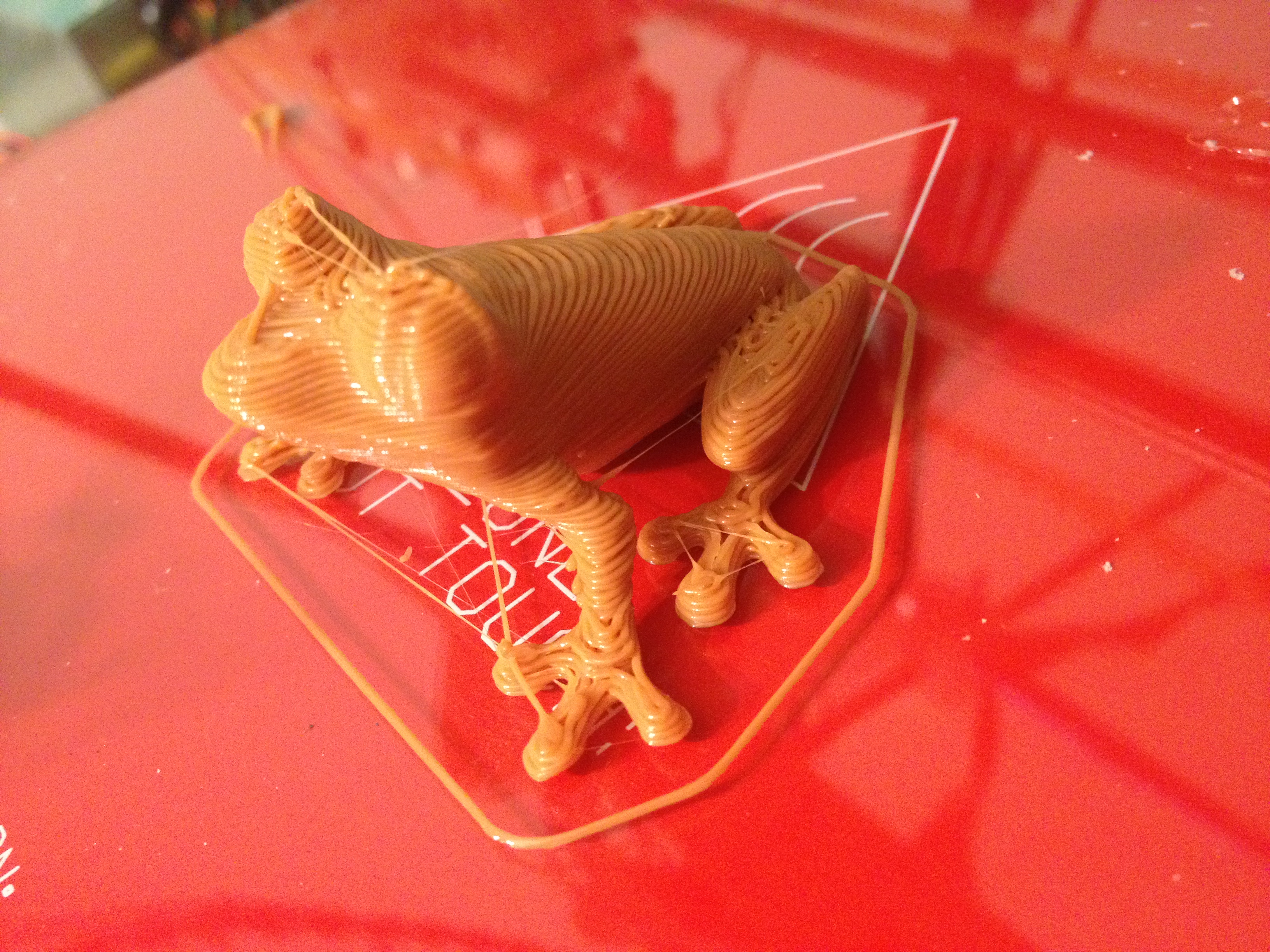
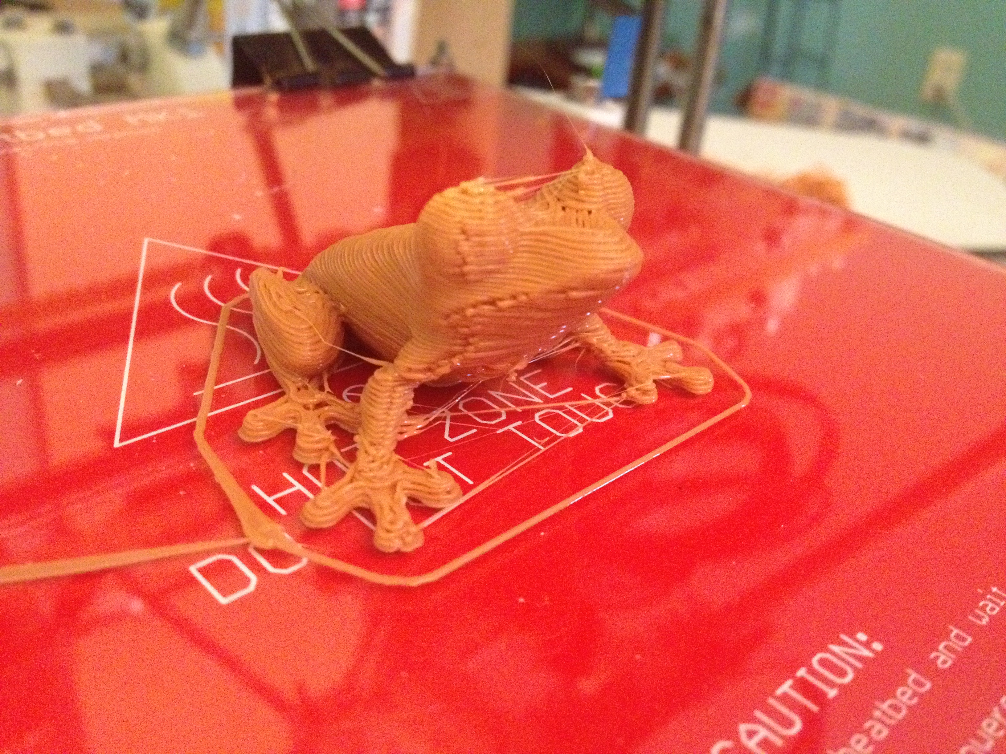
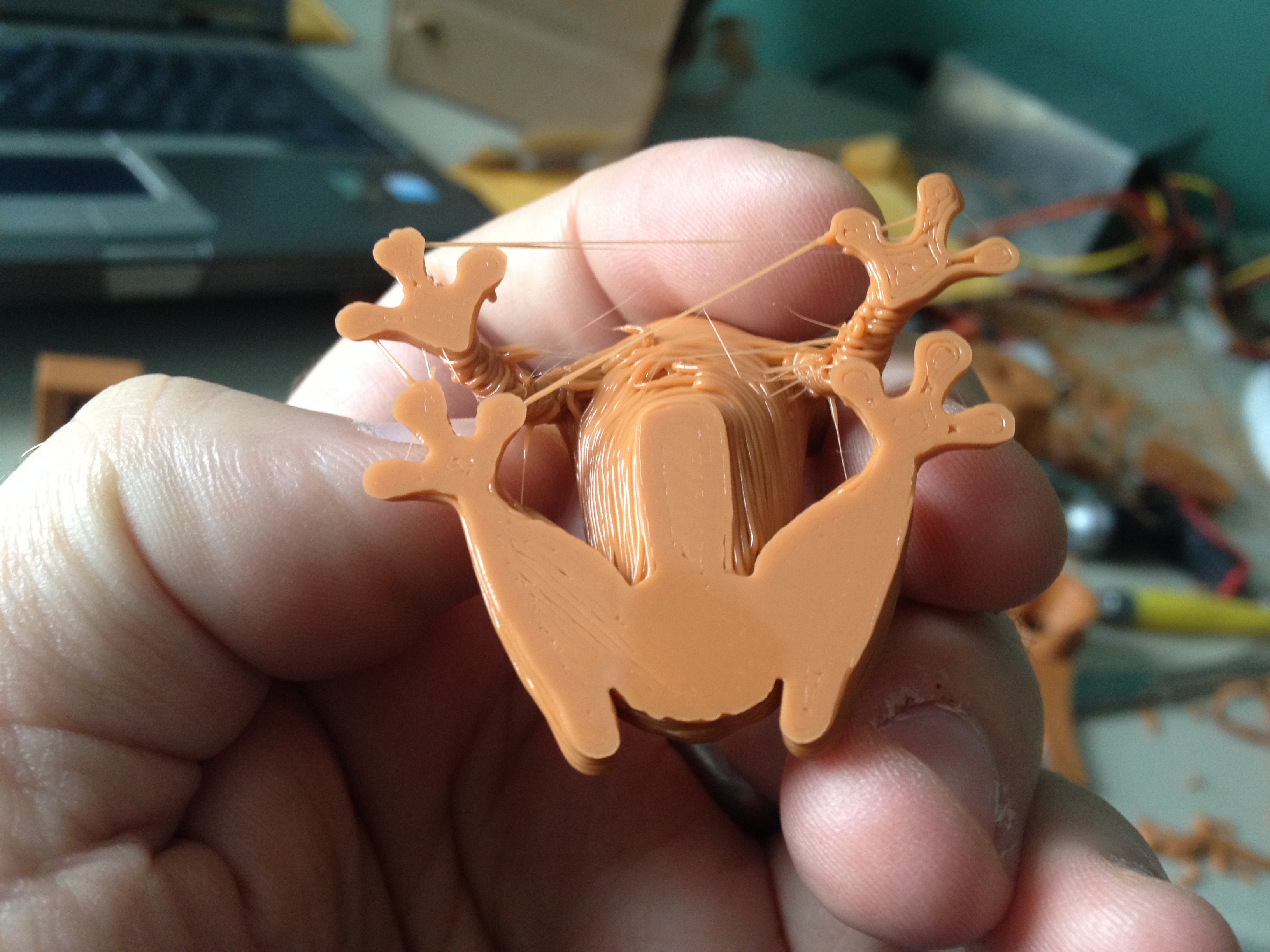
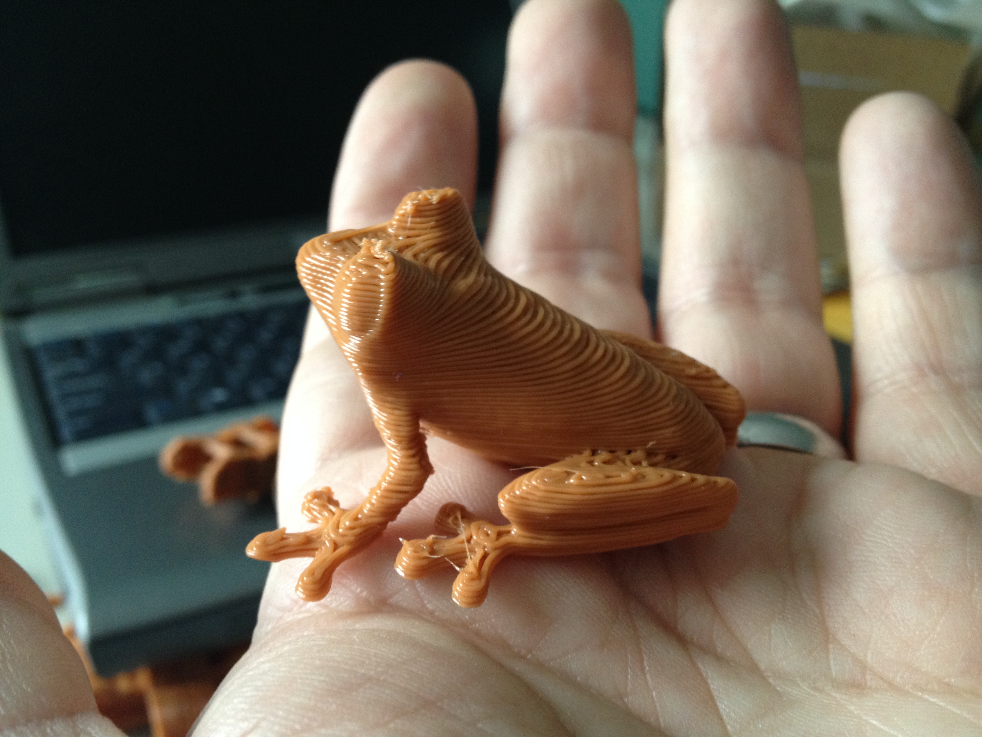
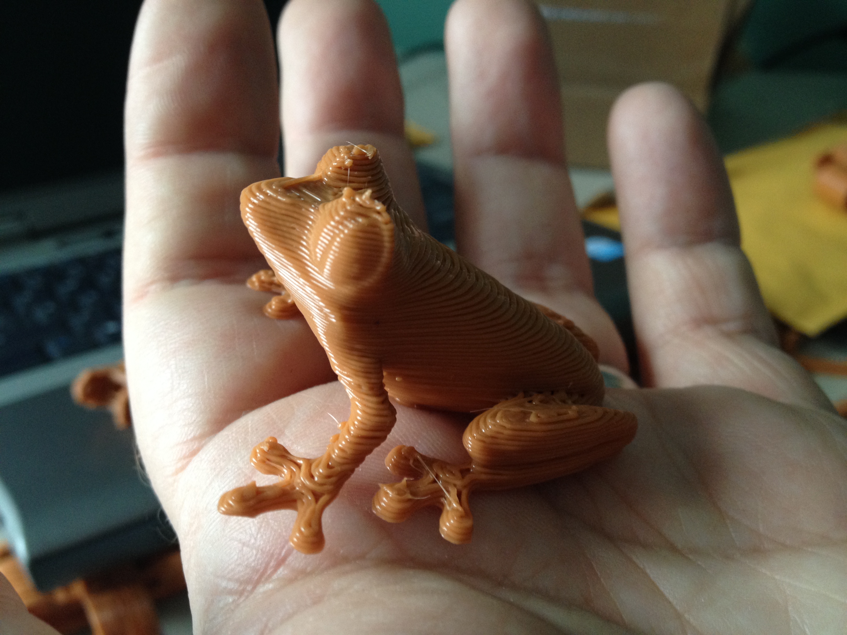
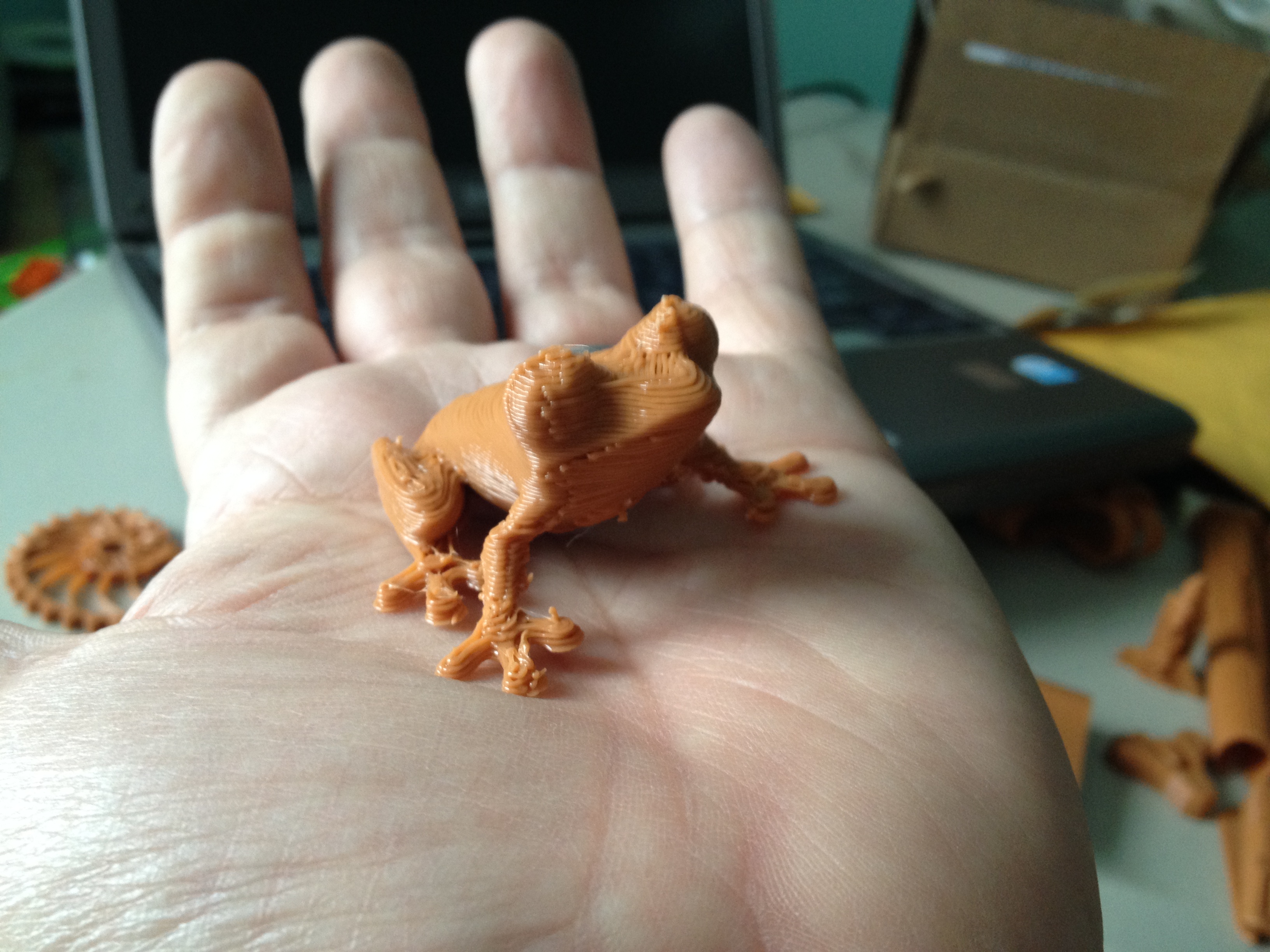
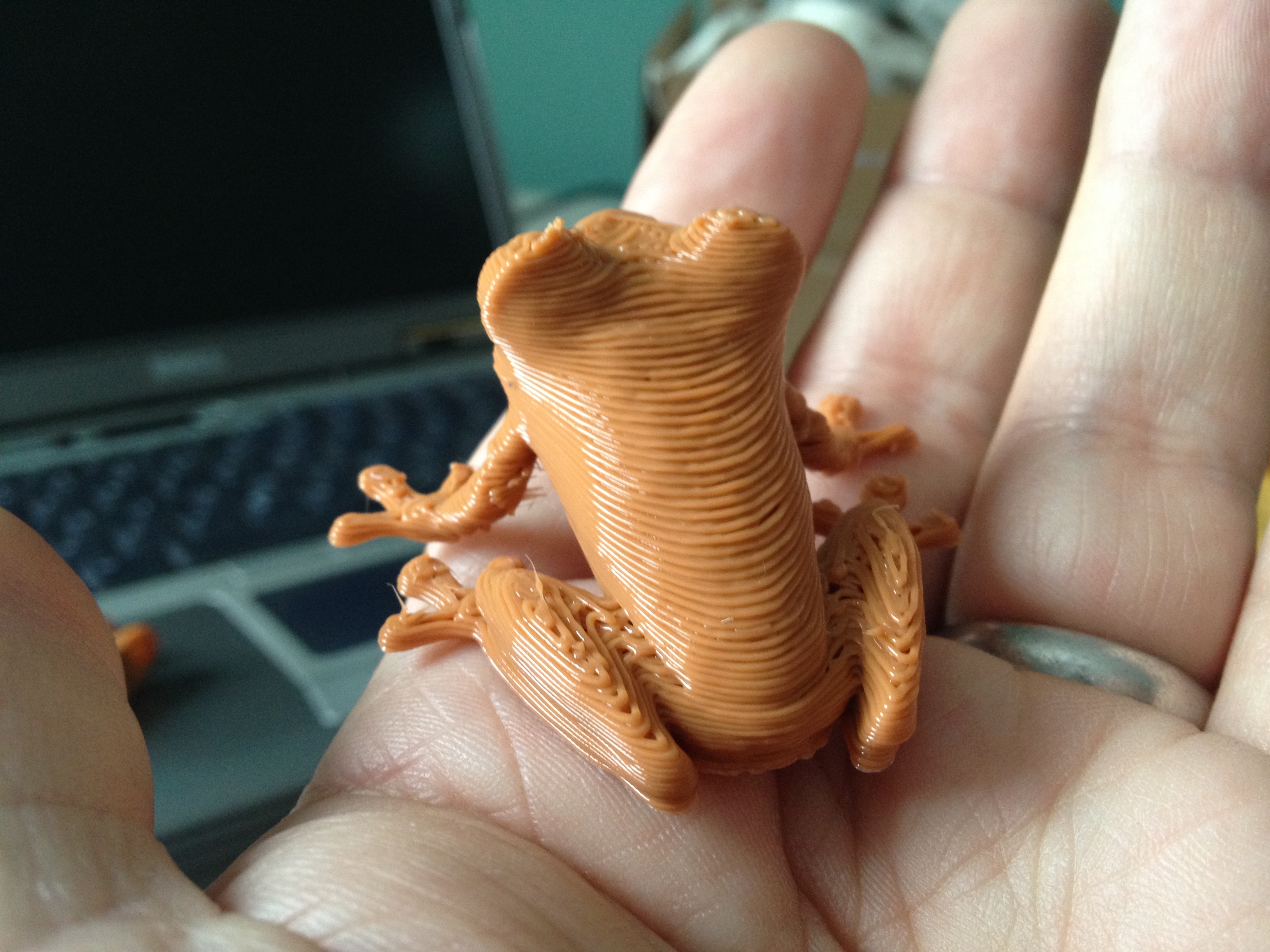
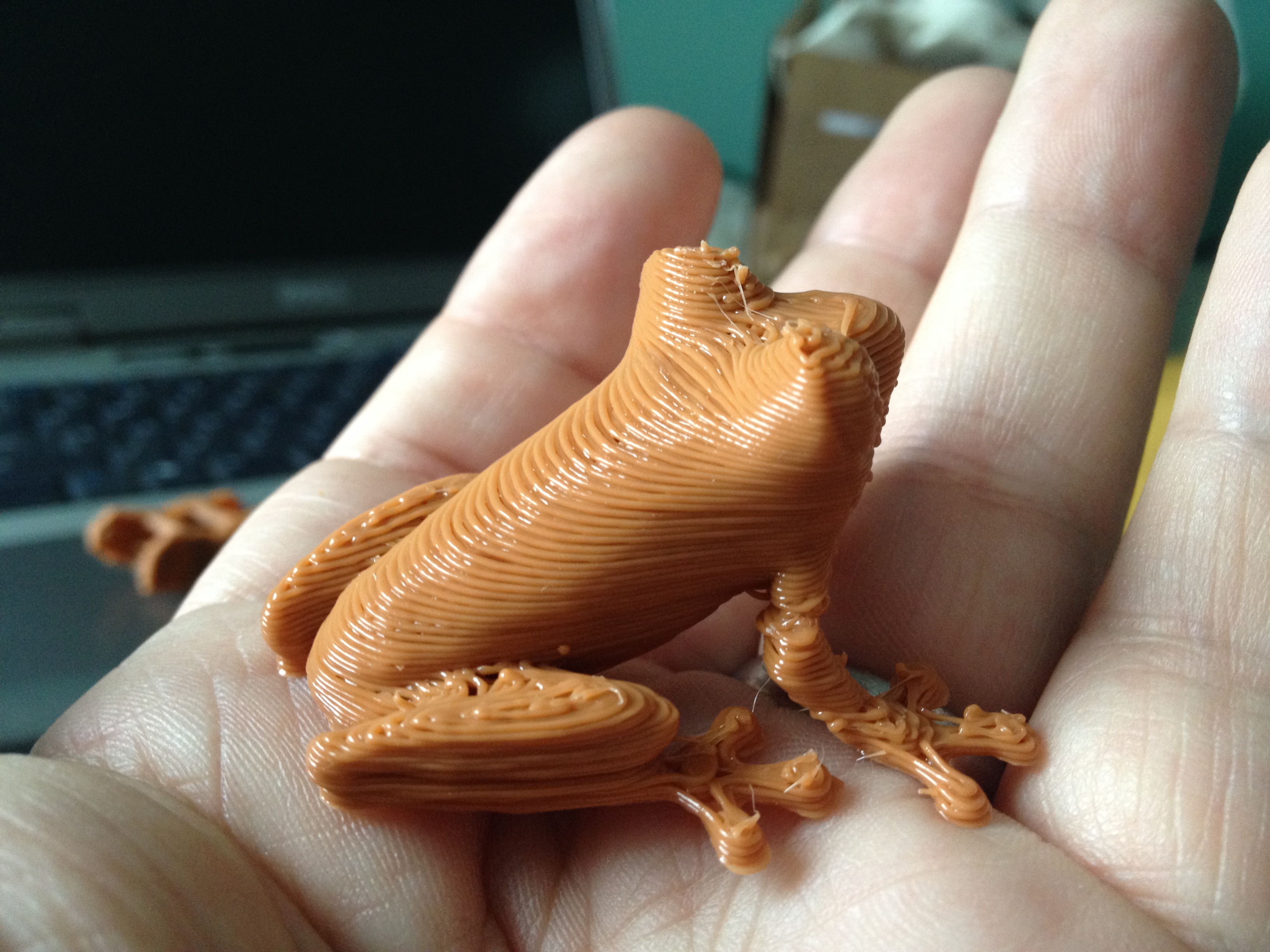
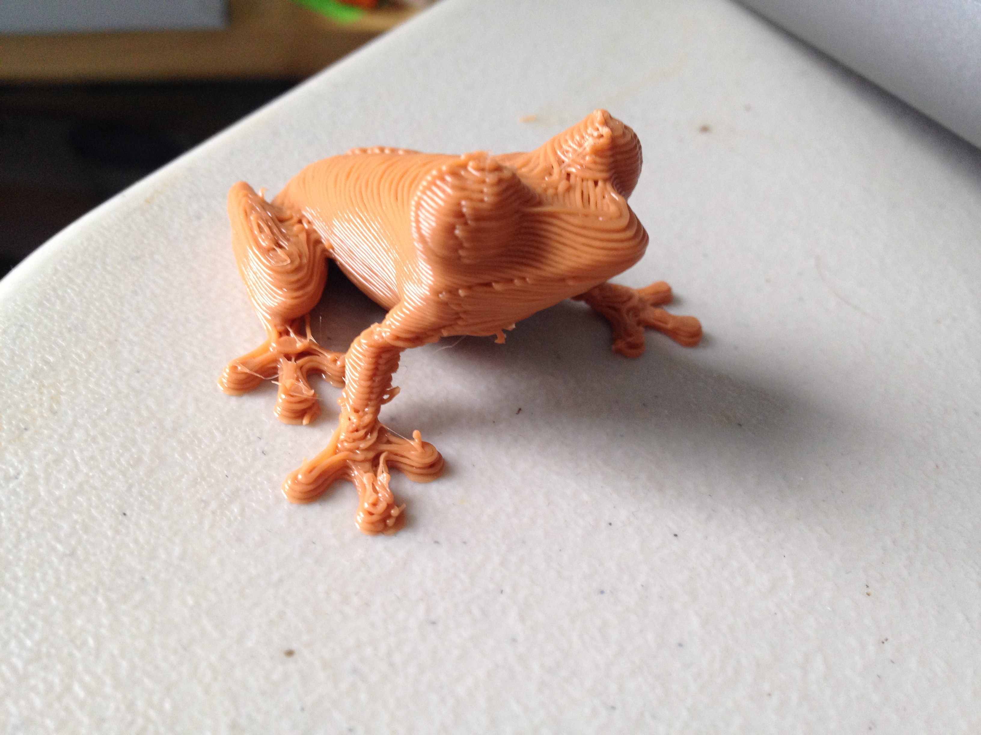
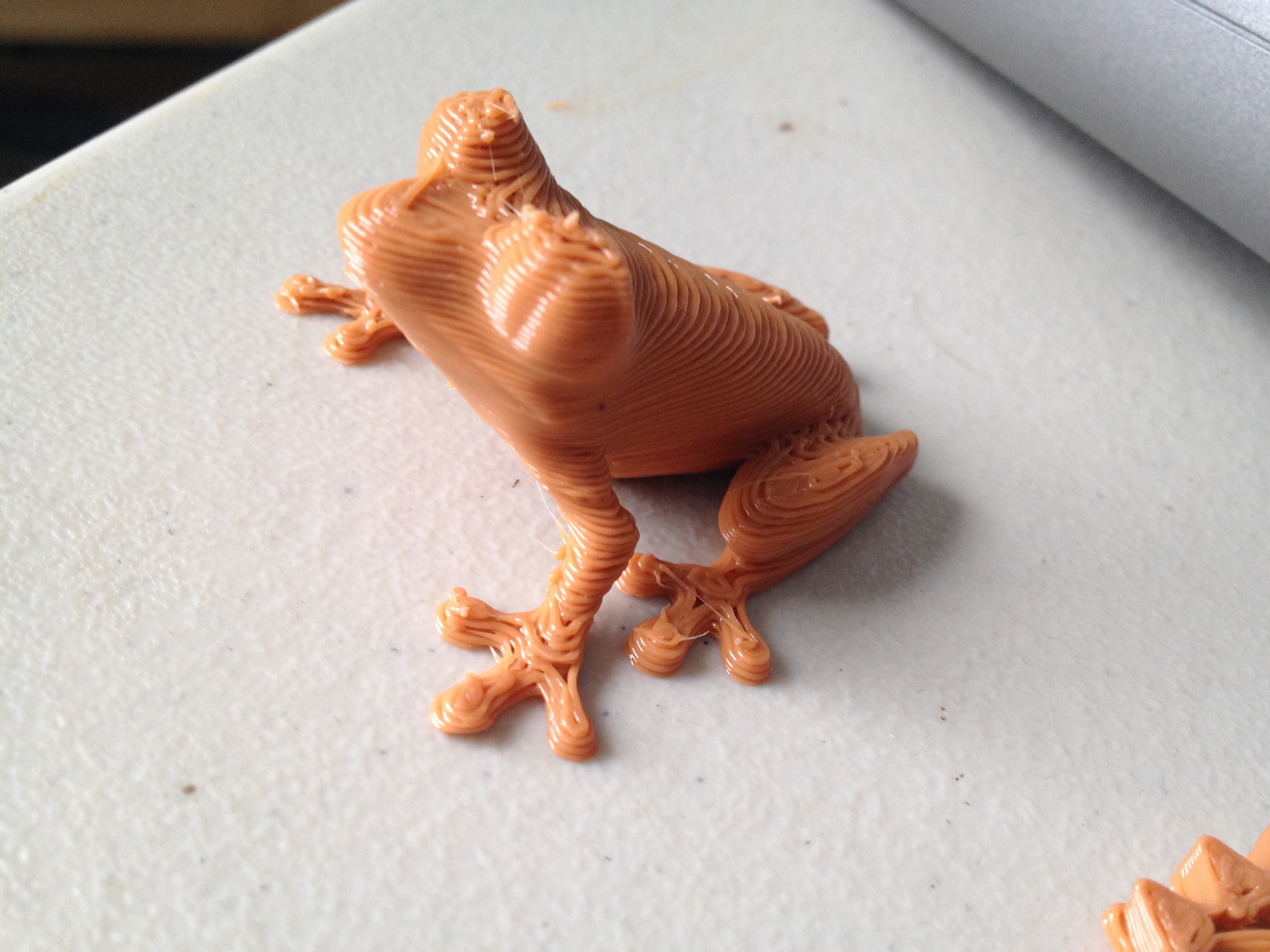
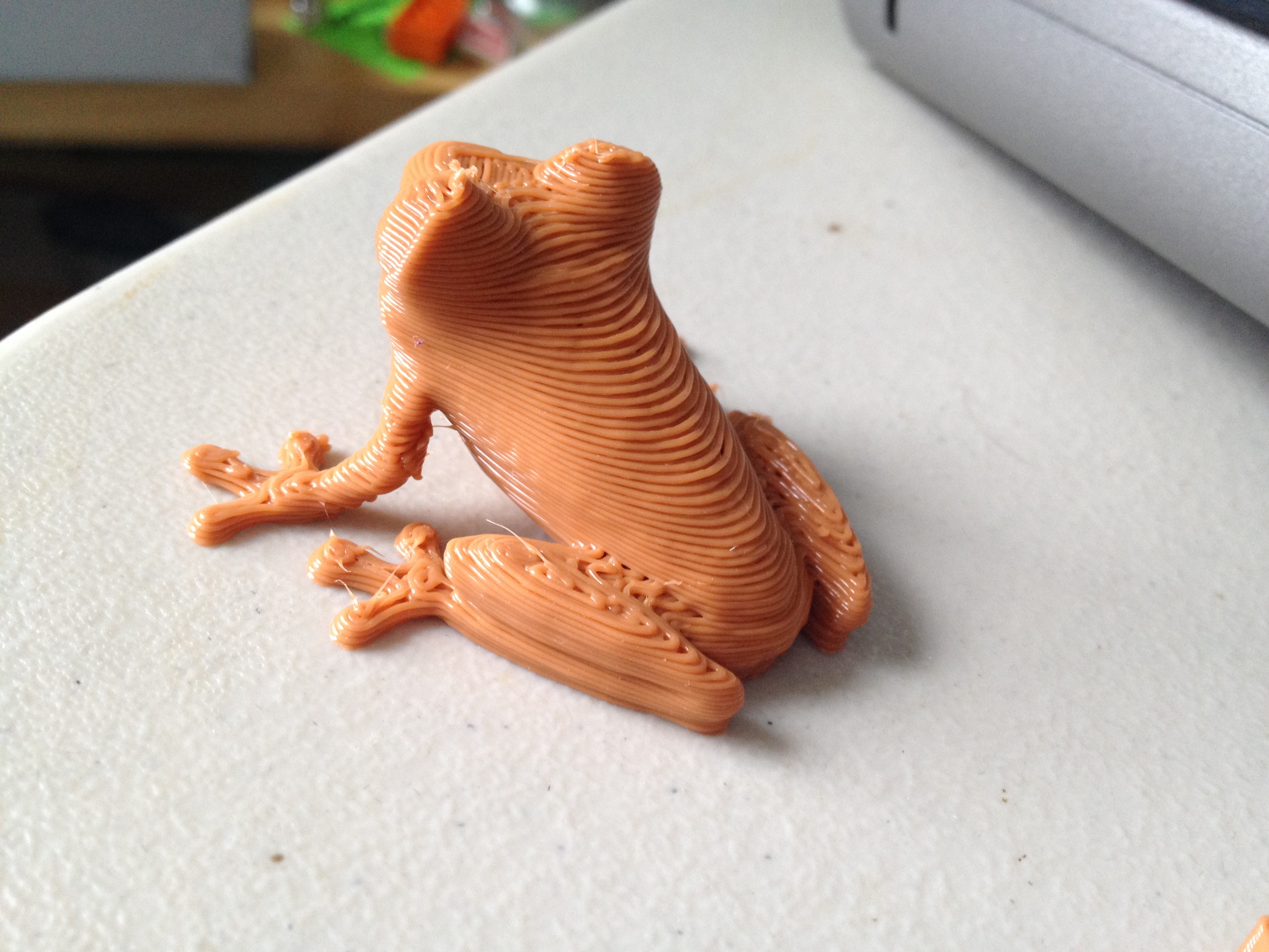
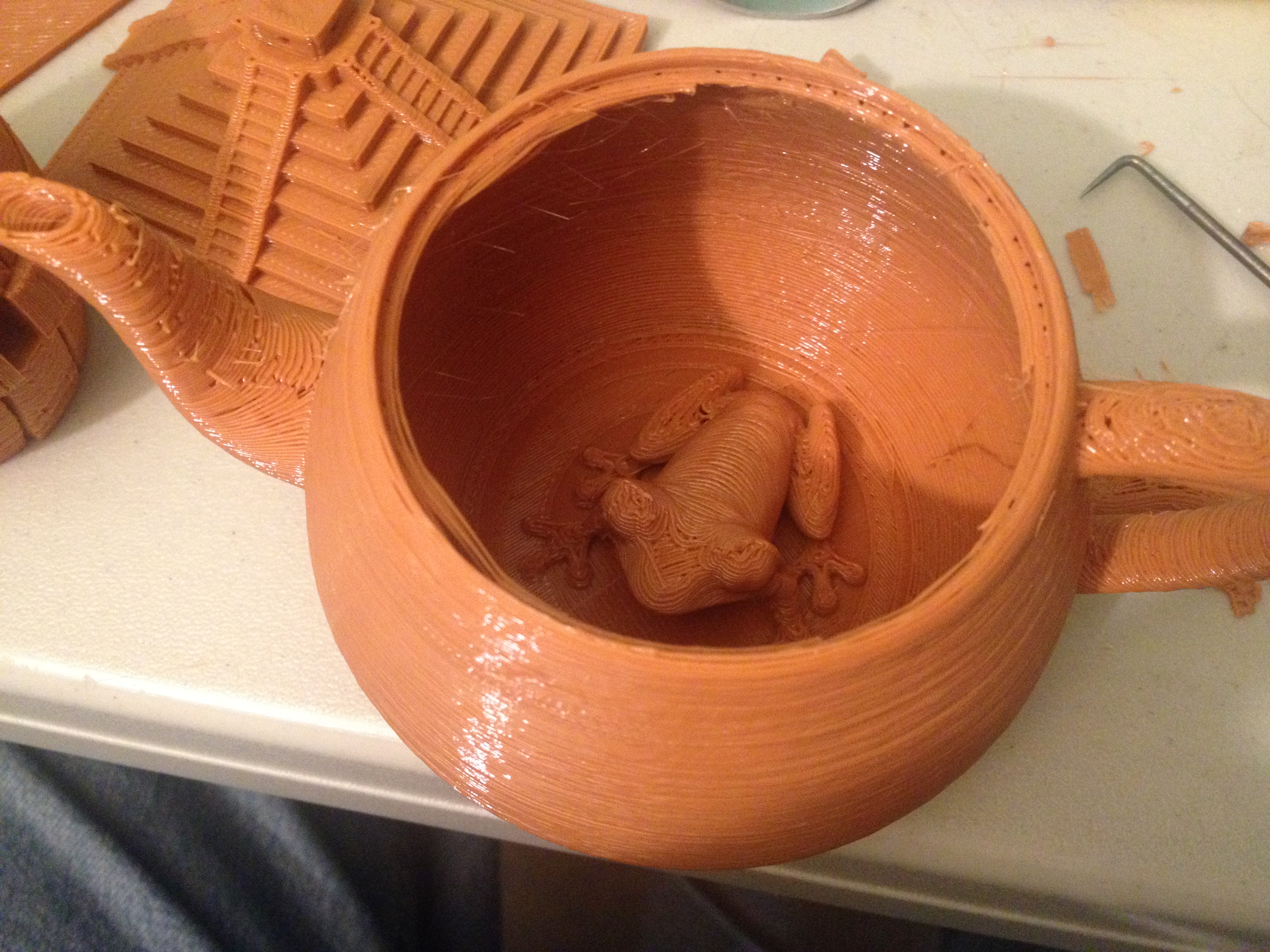
Treefrog – February 14, 2014
Somehow, up until this point, I had never printed a Treefrog!
Yeah that’s a lot of pictures of a frog, but I really liked how it came out. 🙂
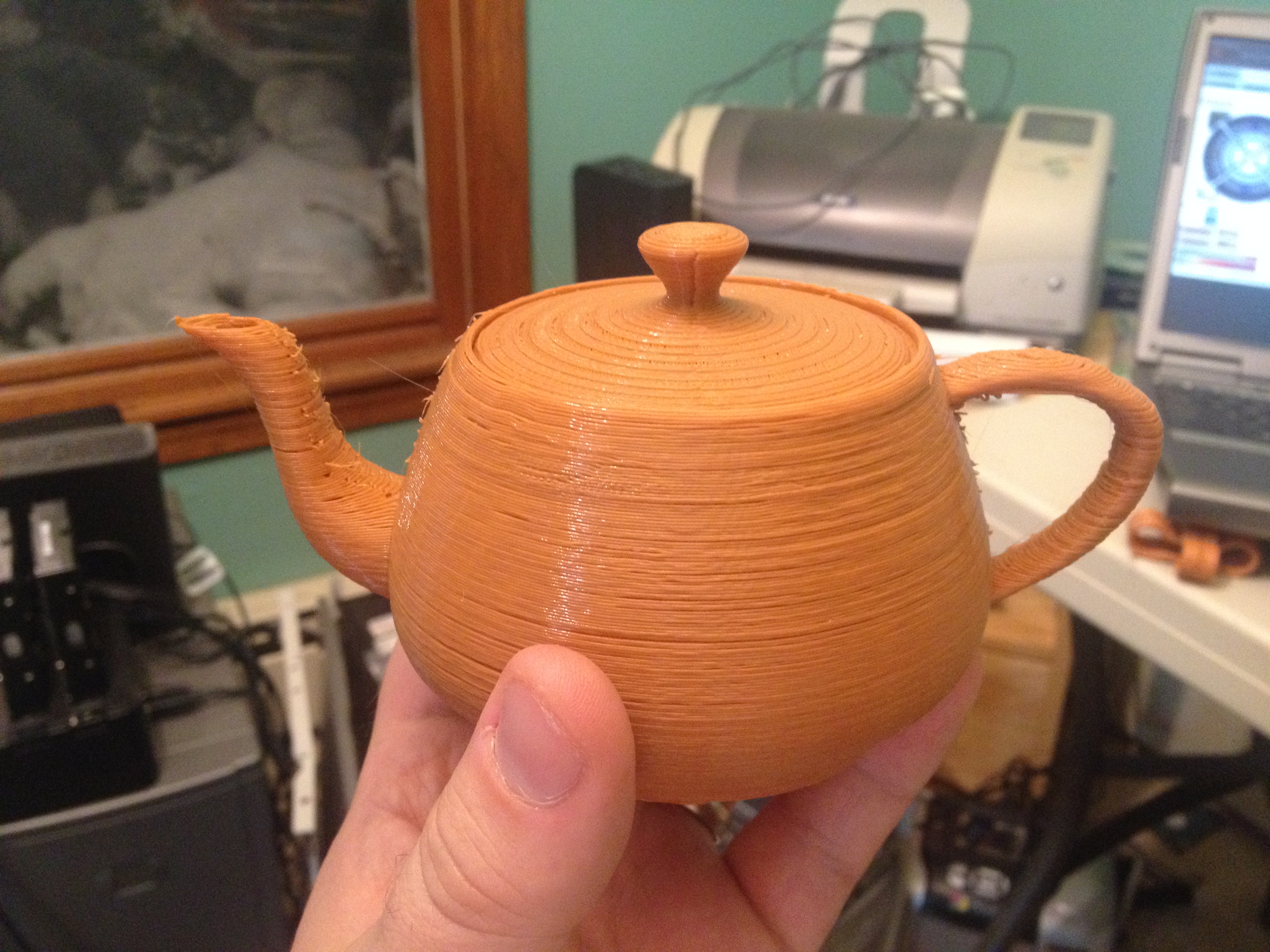
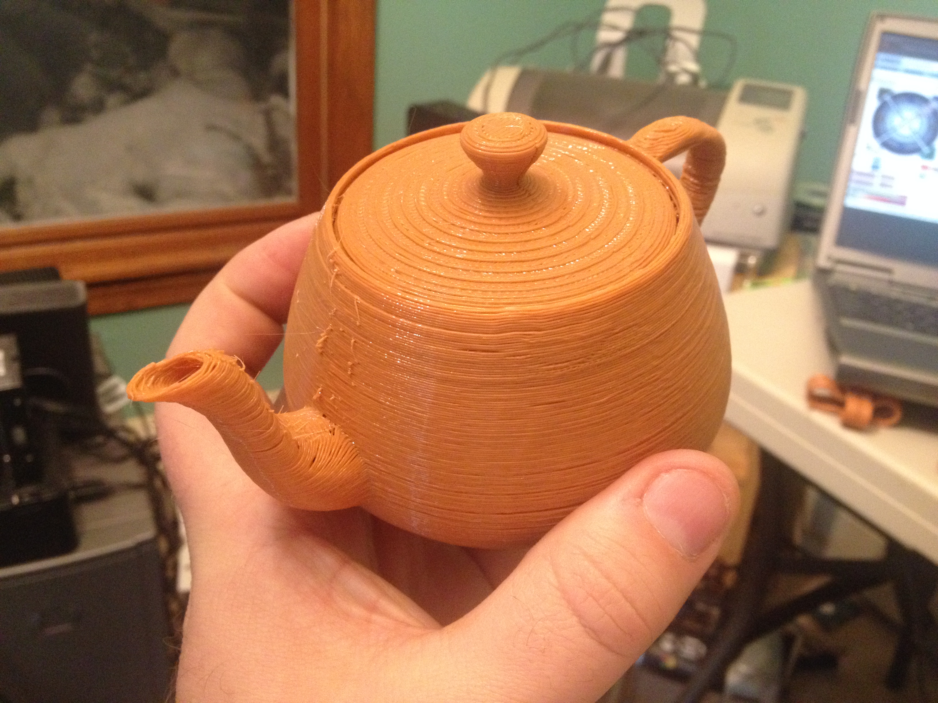
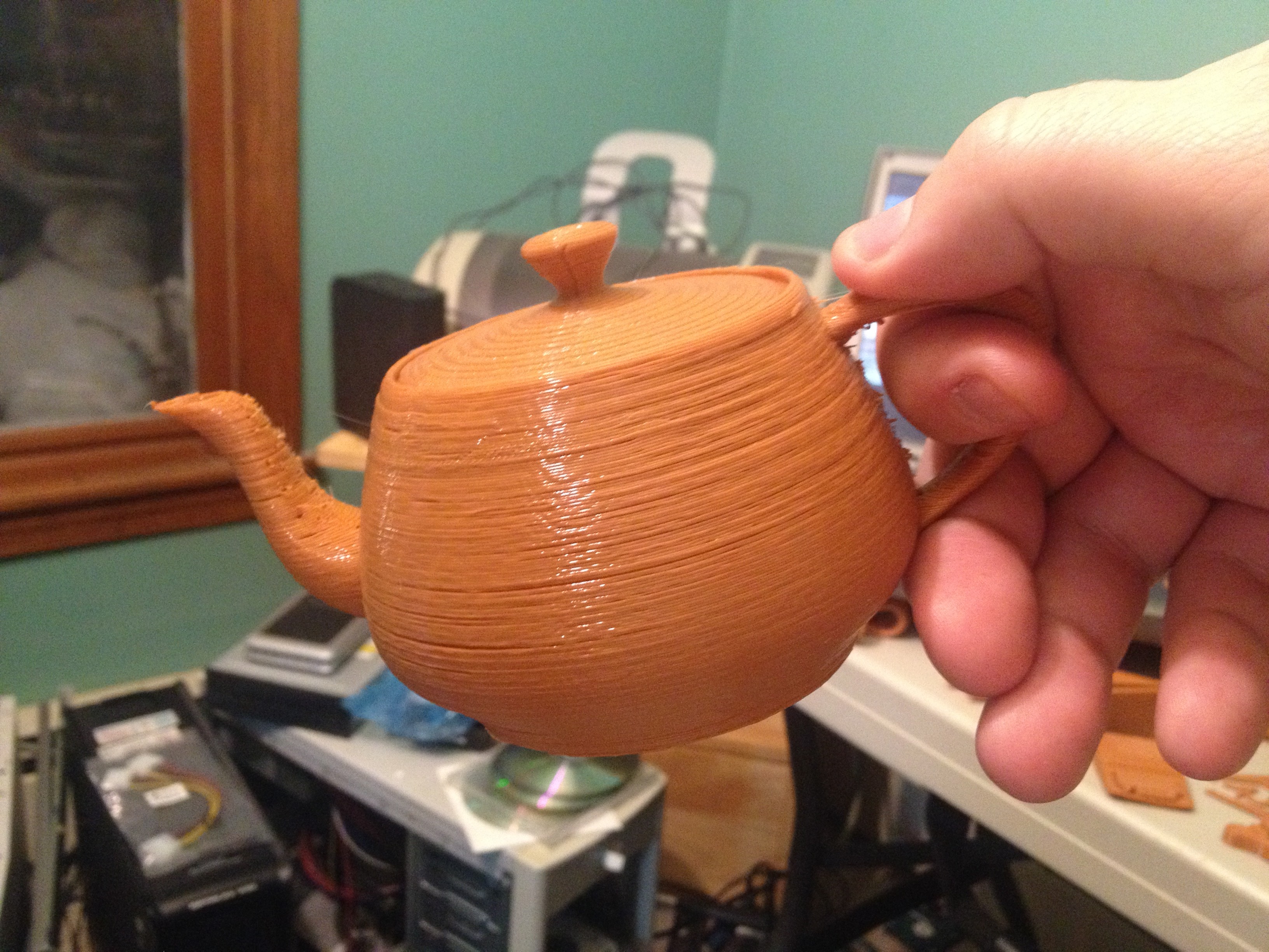
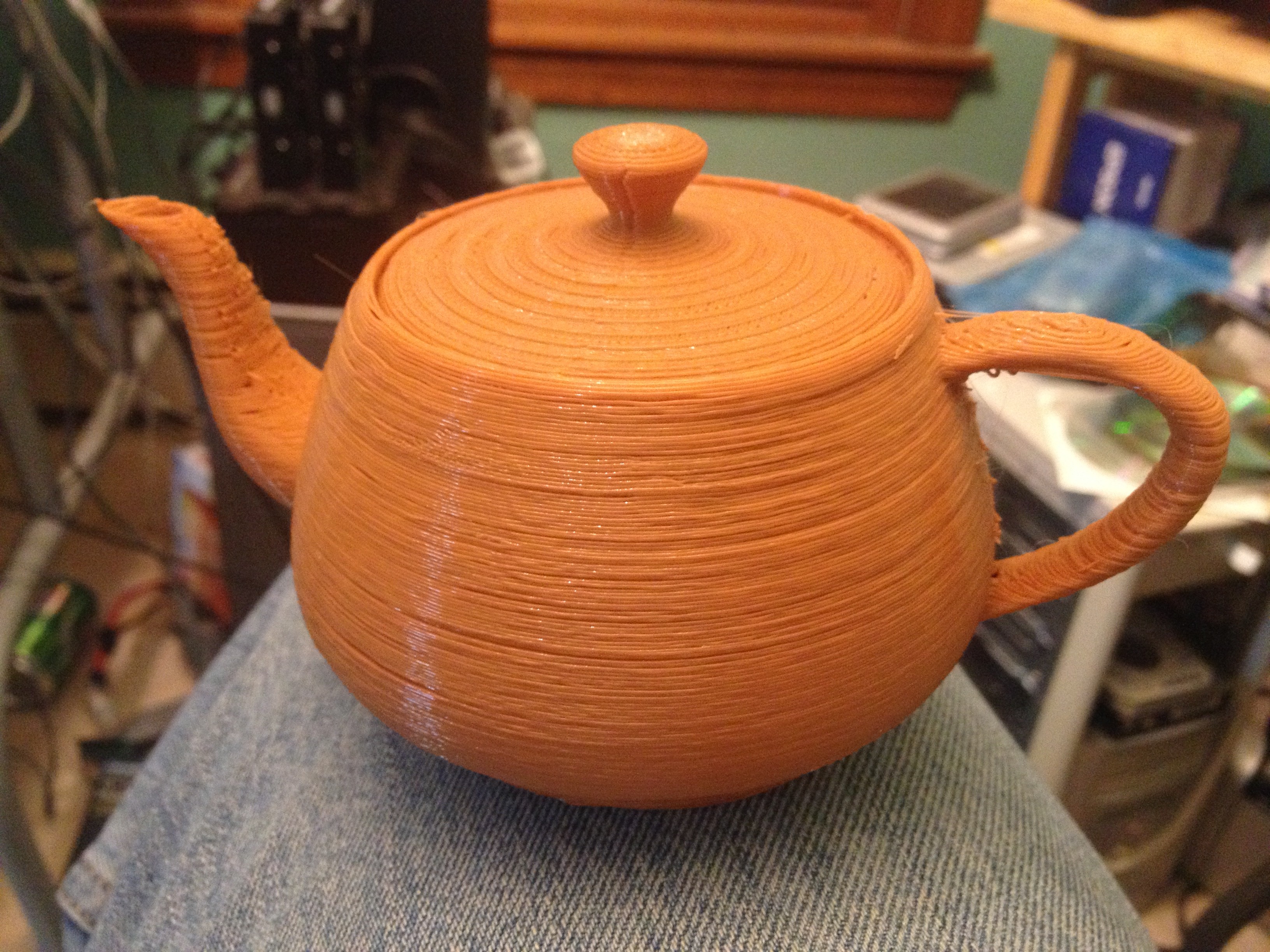
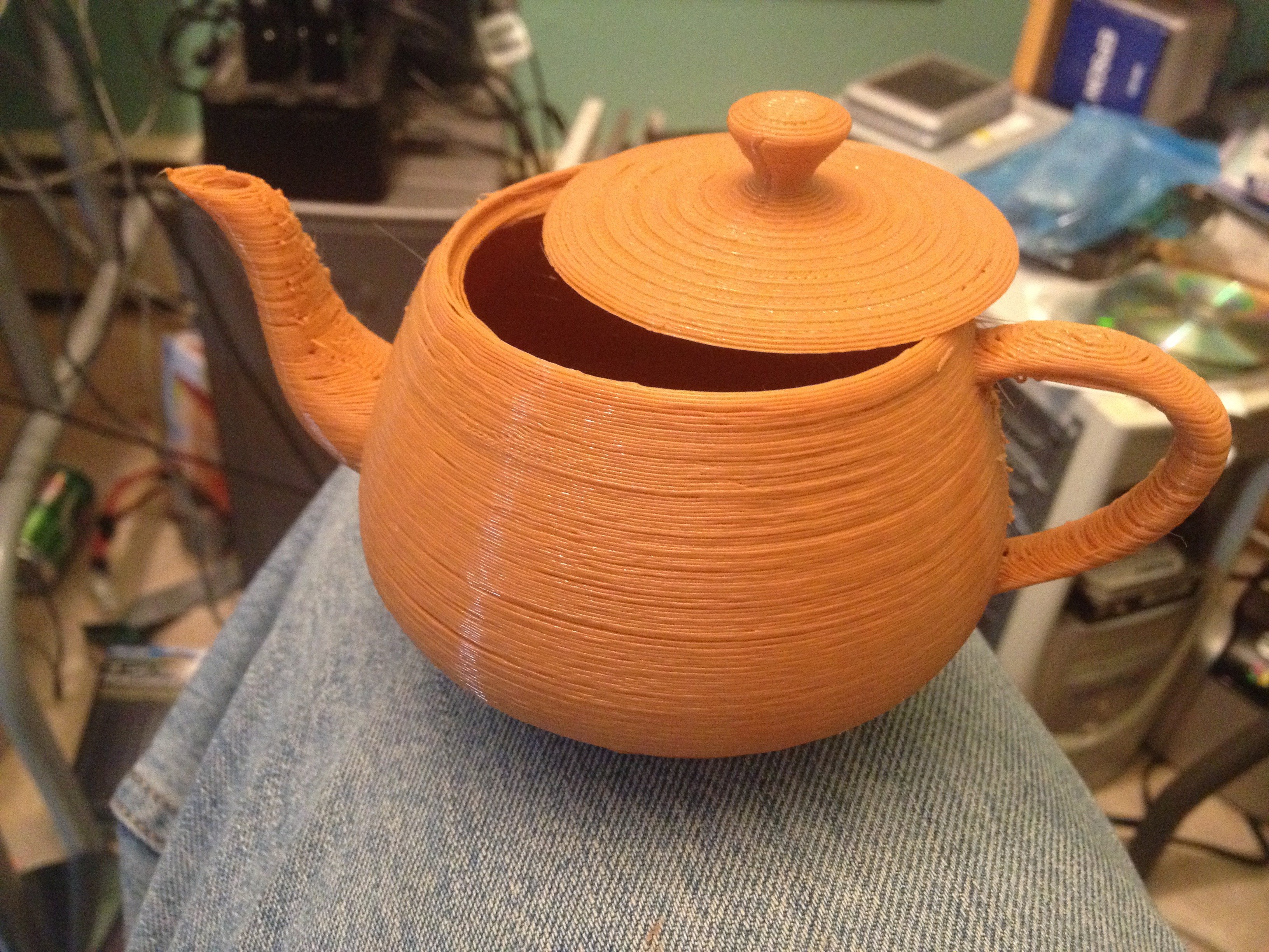
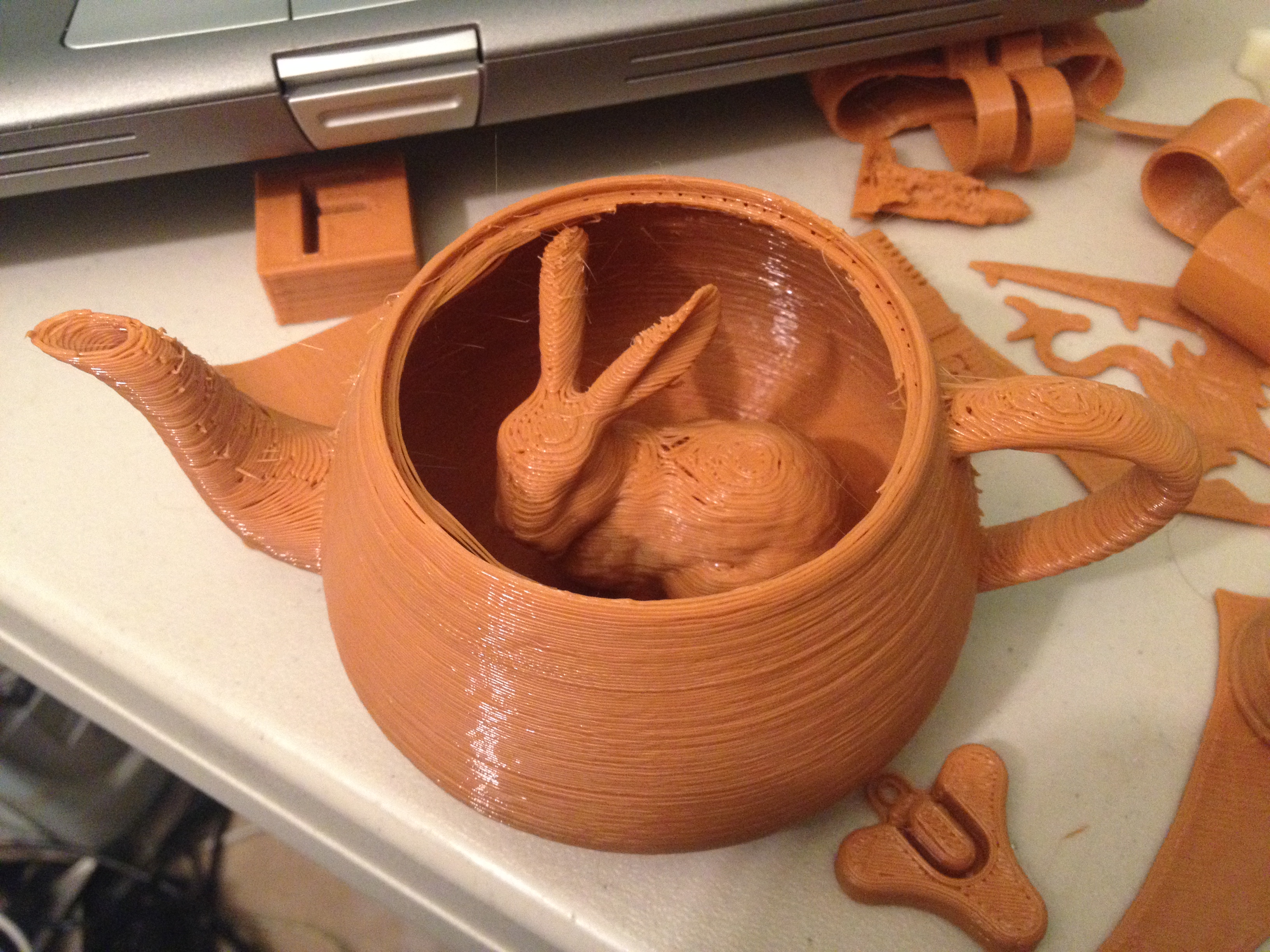
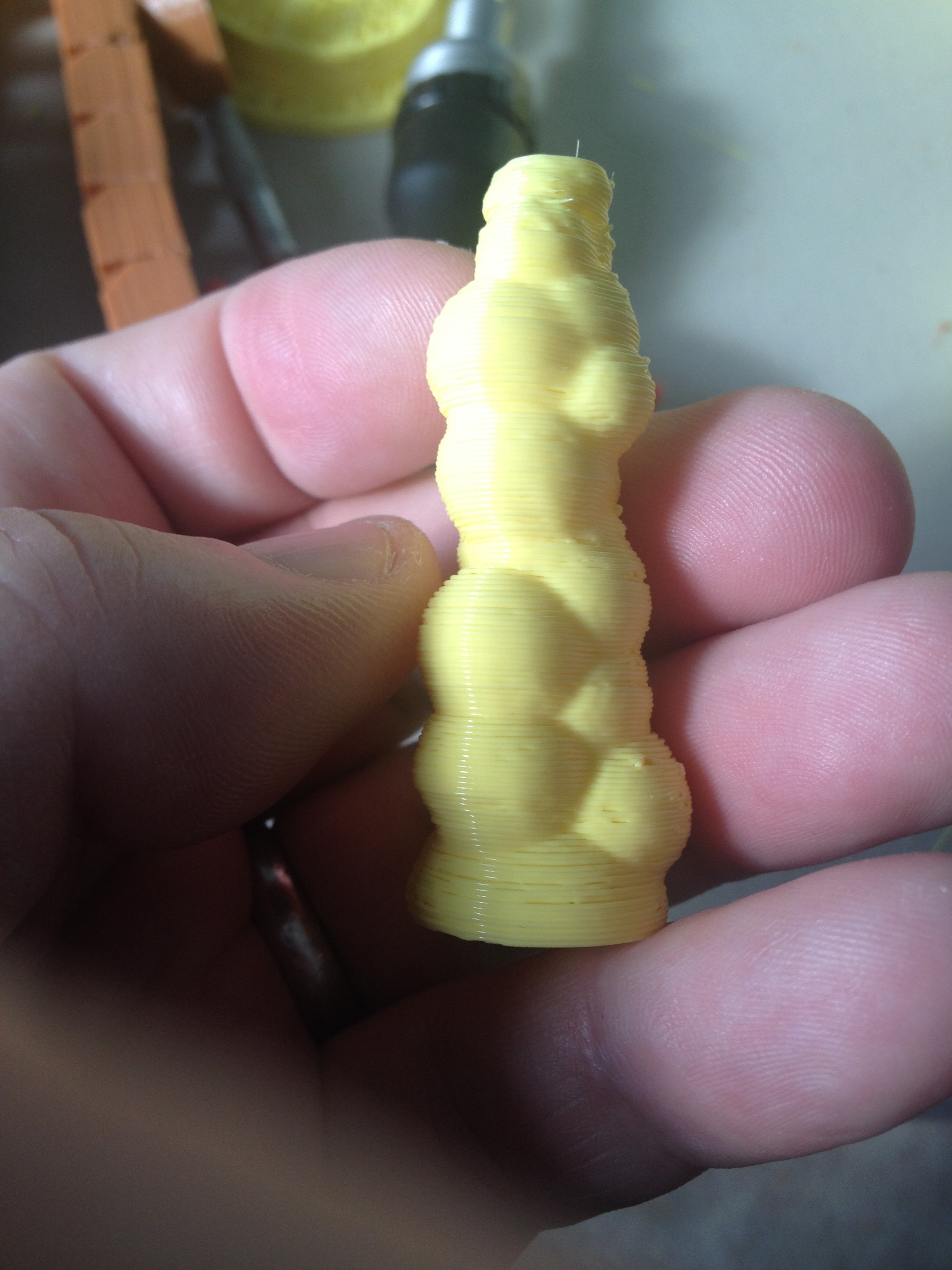
Utah Teapot – February 15, 2014
This was an old classic (thing #1176 – that’s a low number!) that I’d never gotten around to printing.. Here is the Utah Teapot:
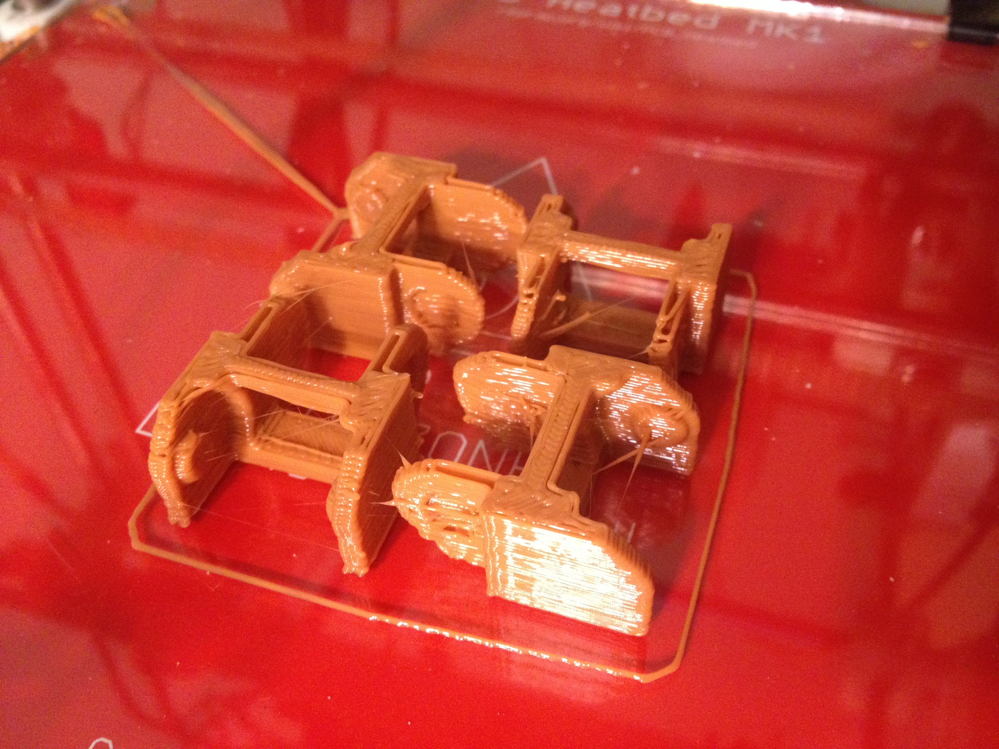
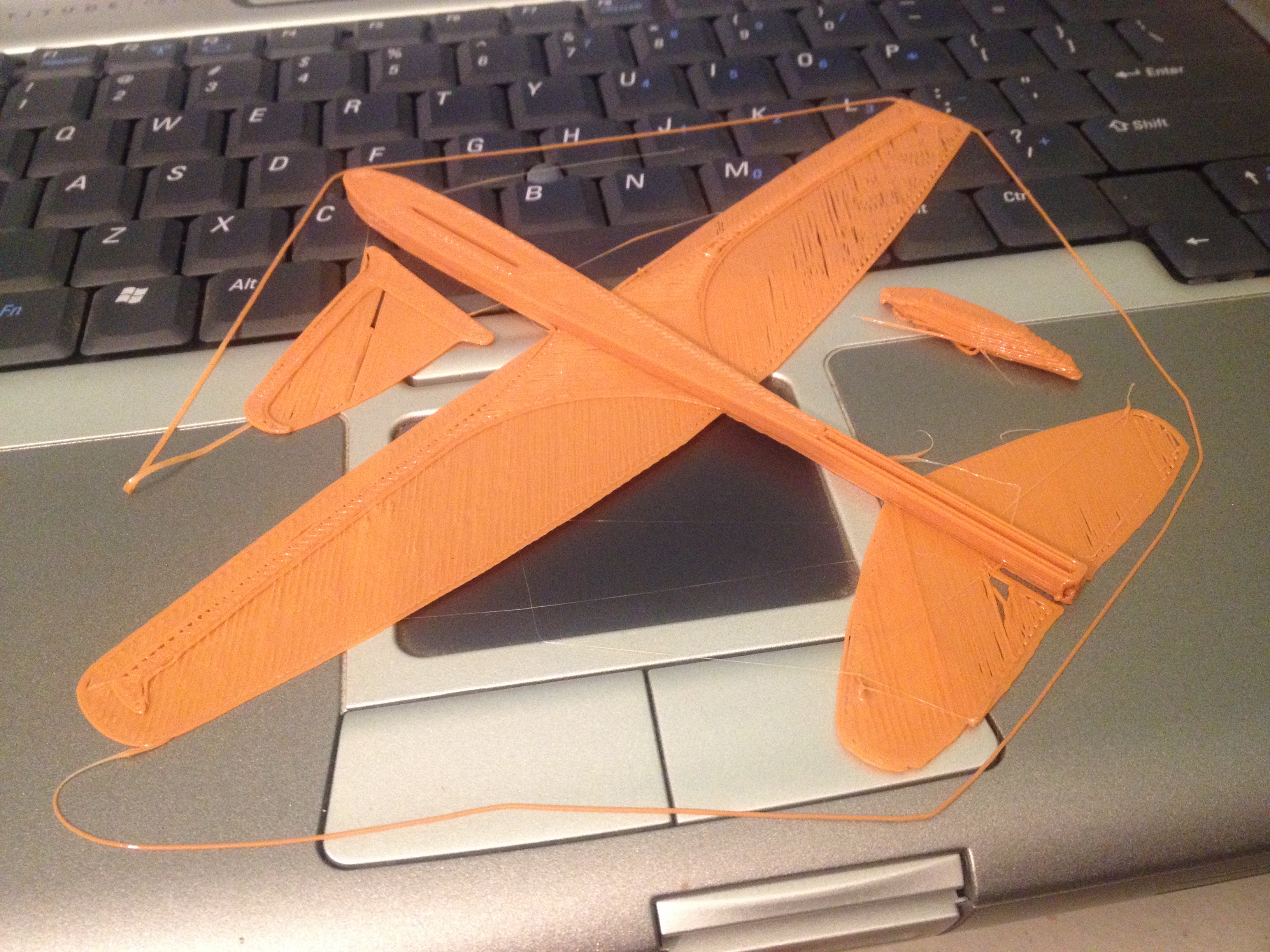
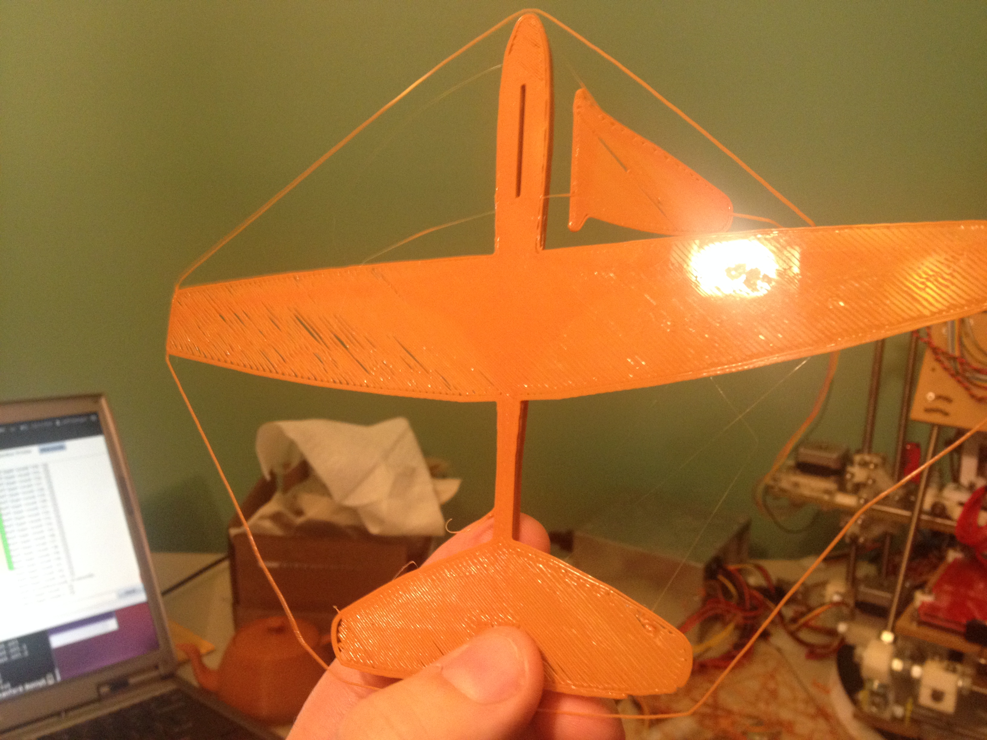
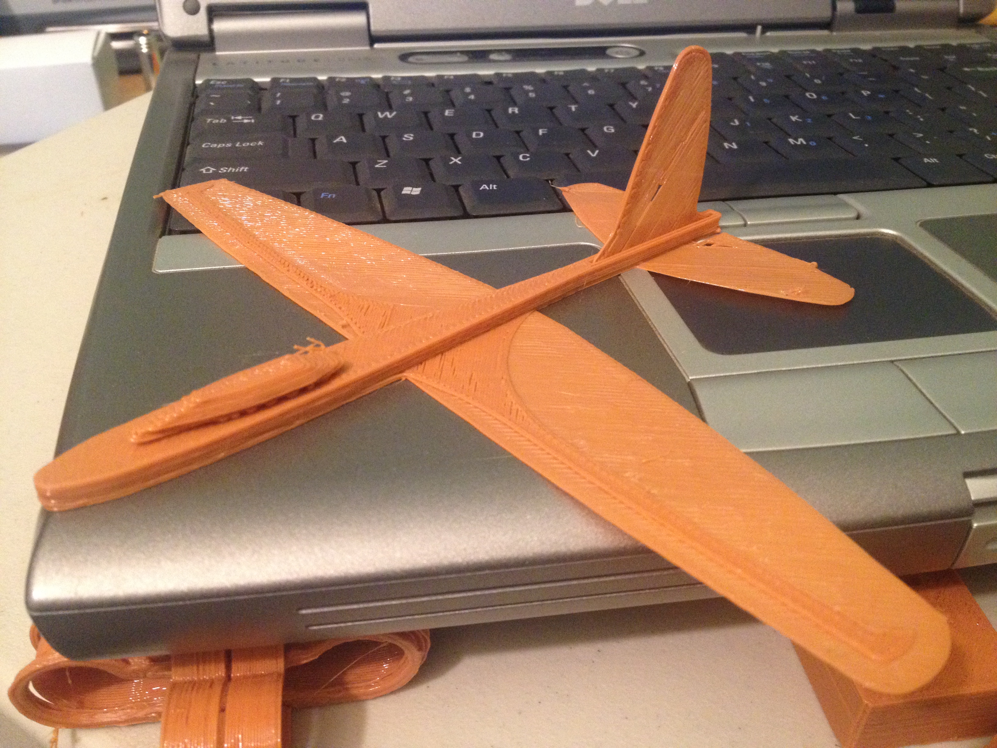
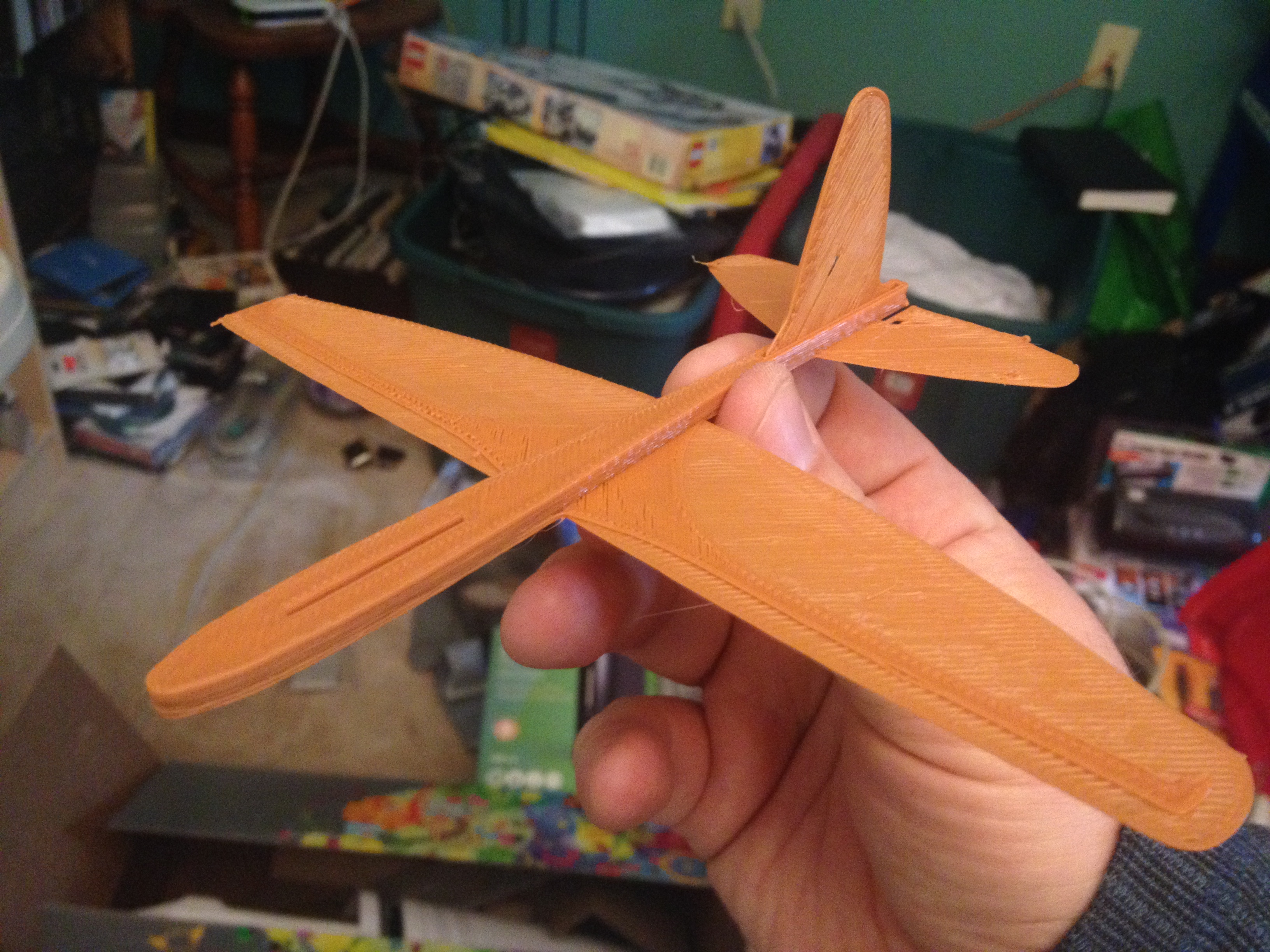
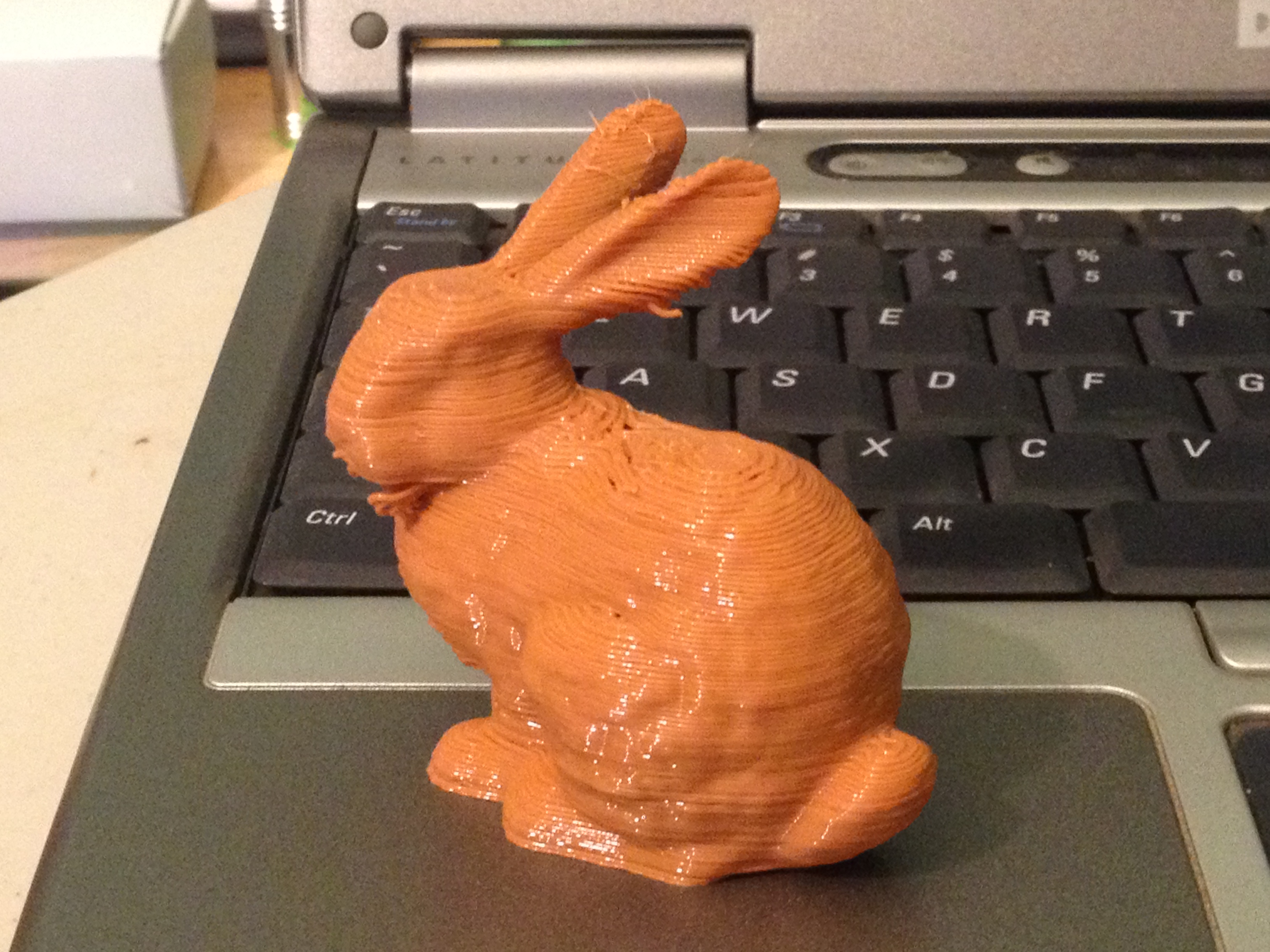
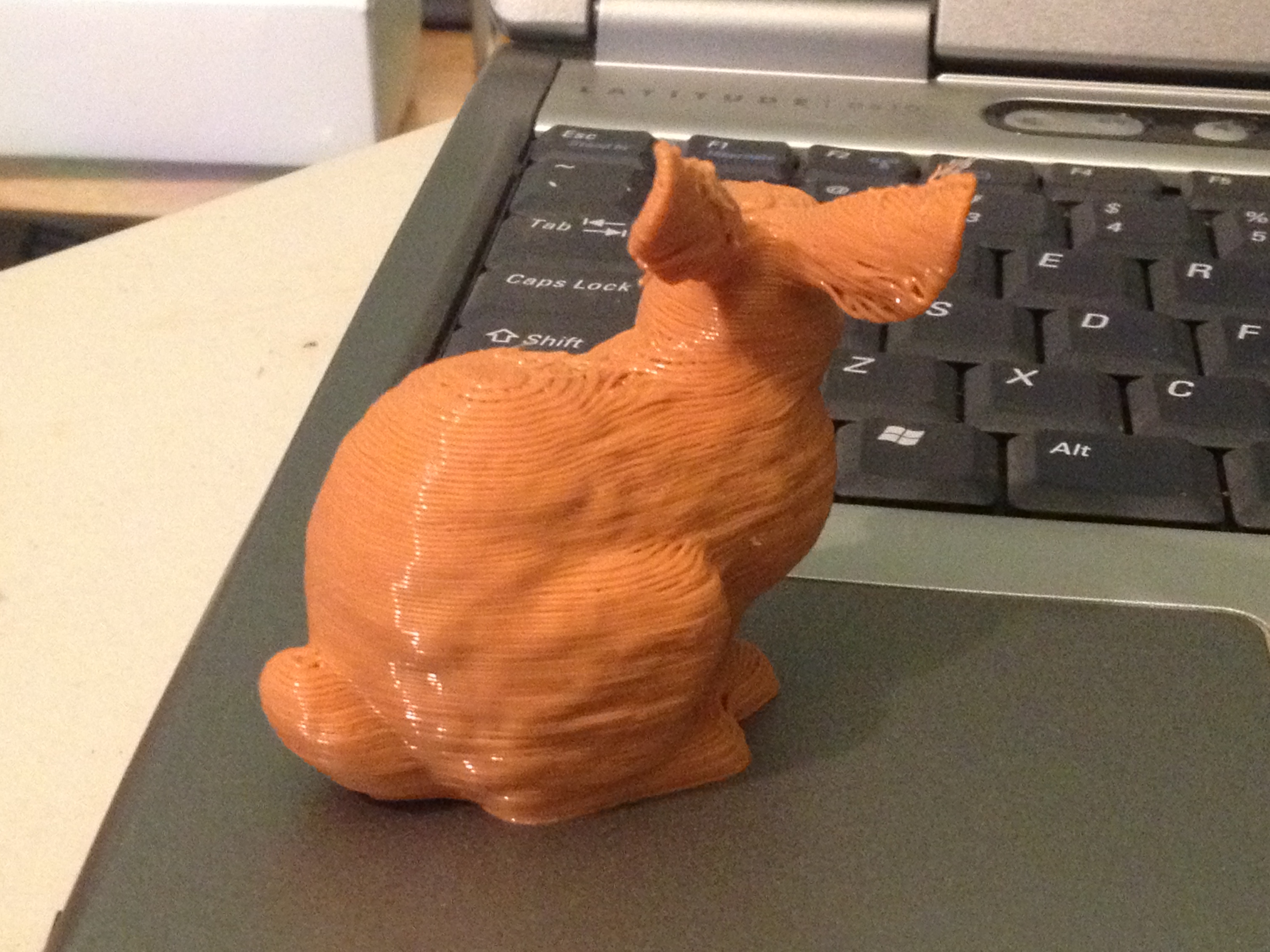
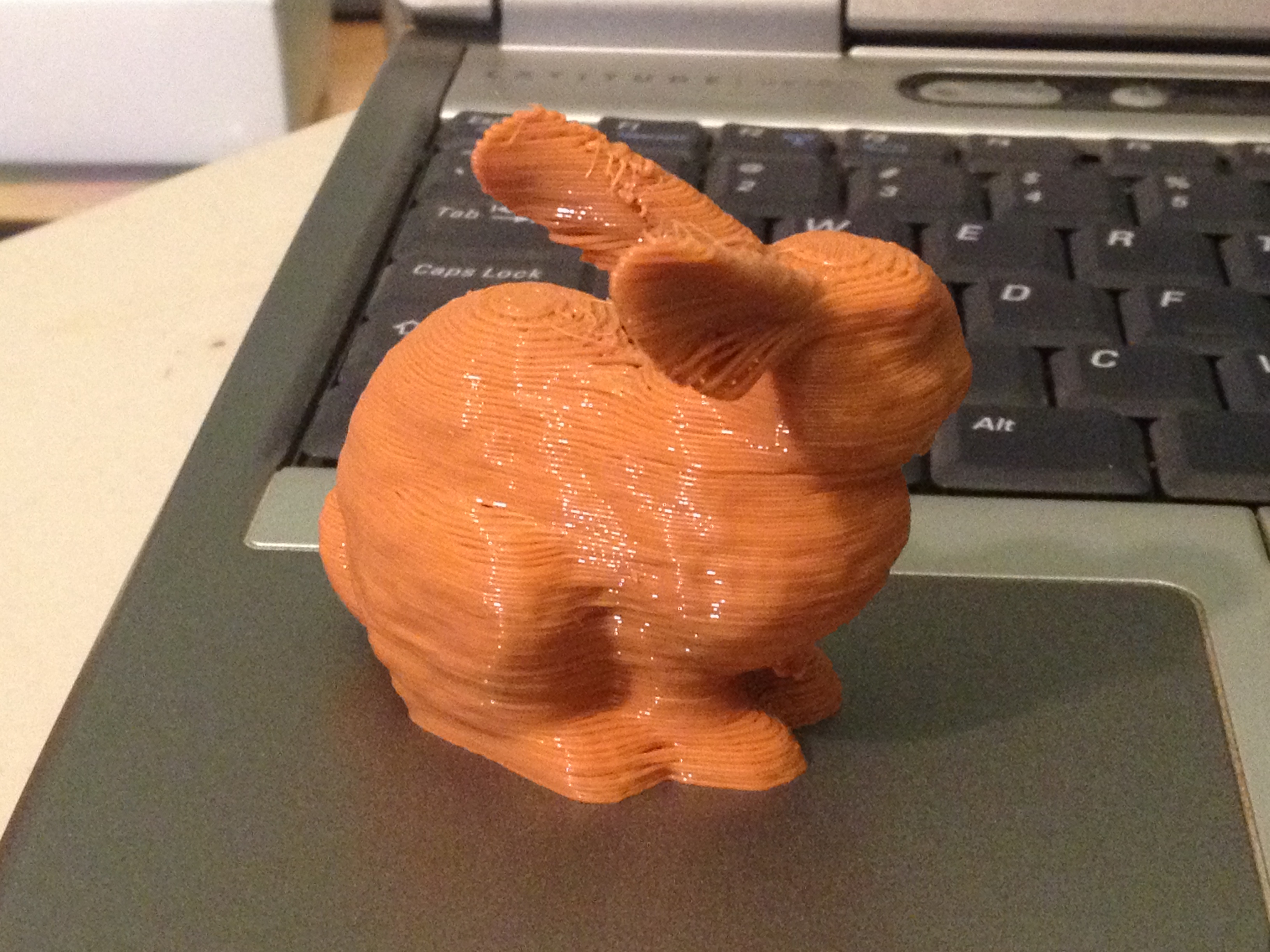
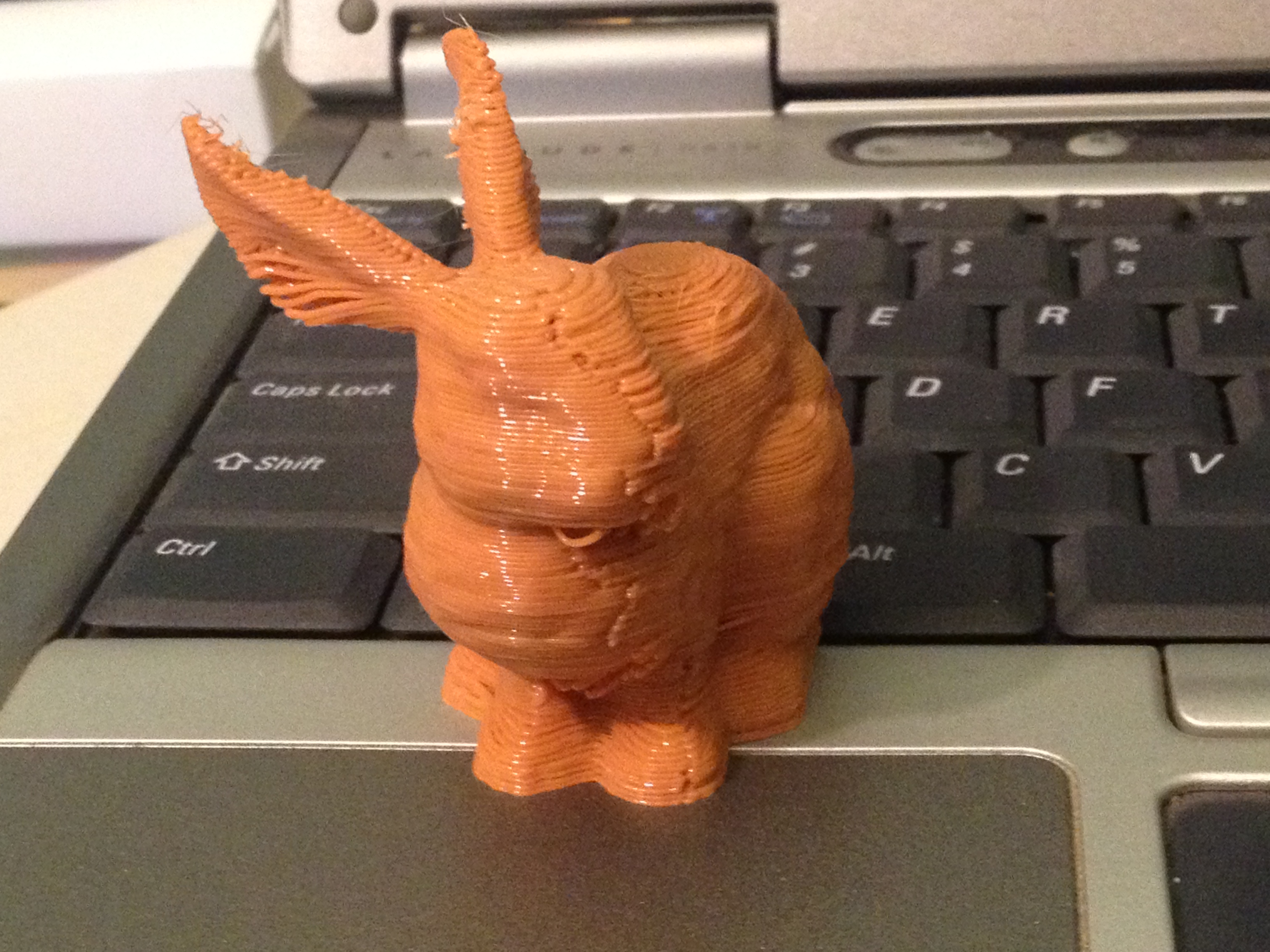
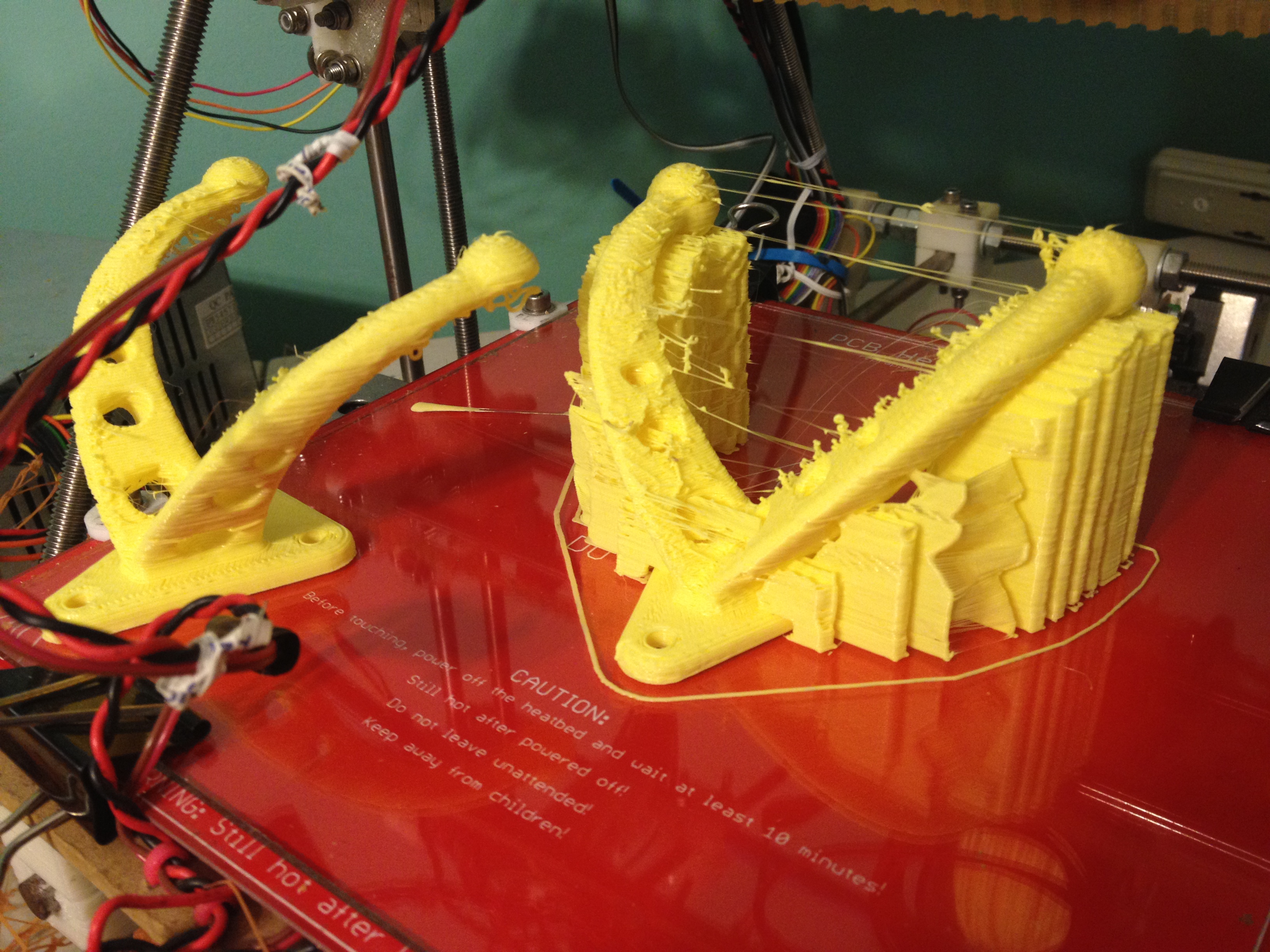
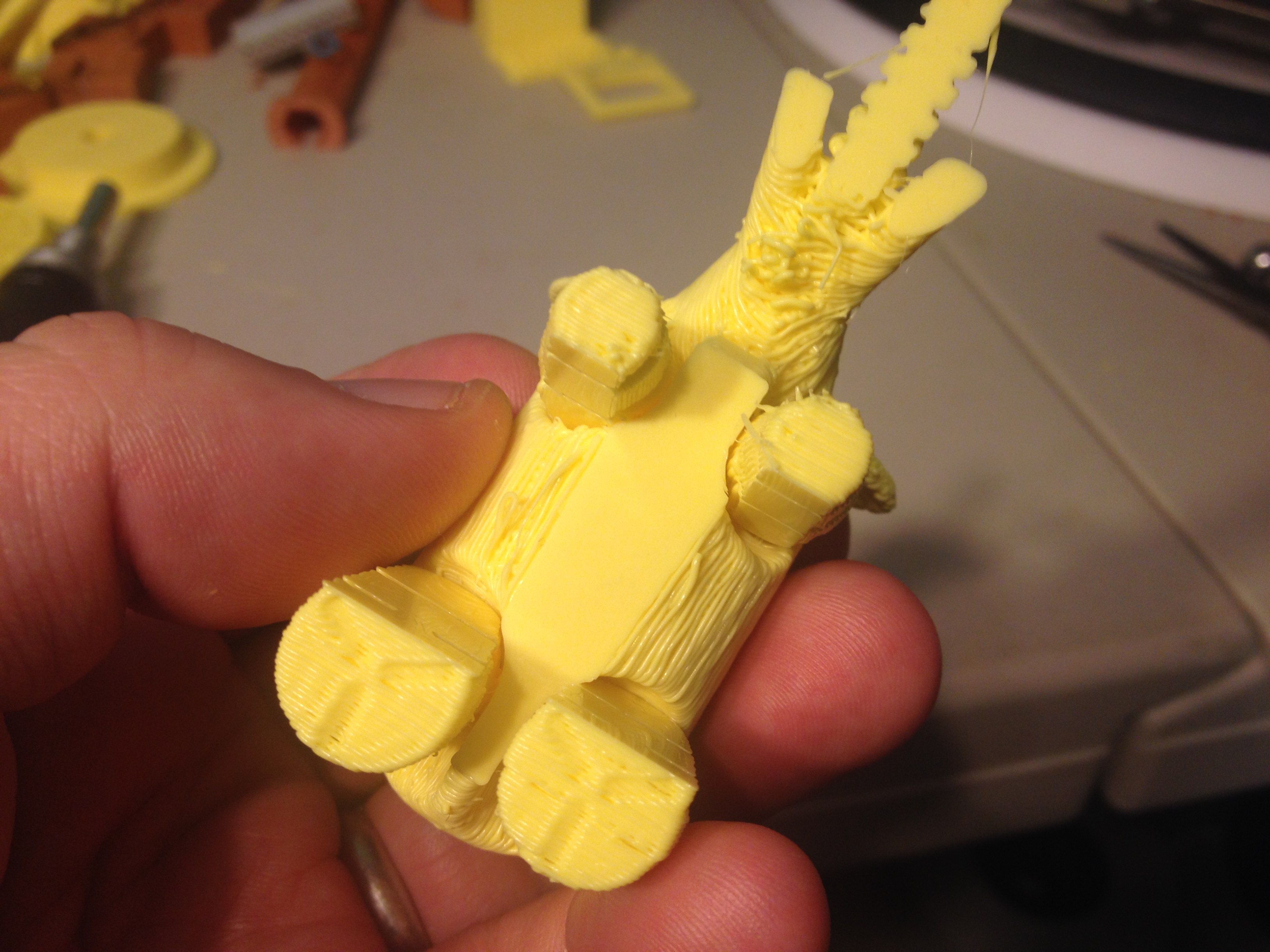
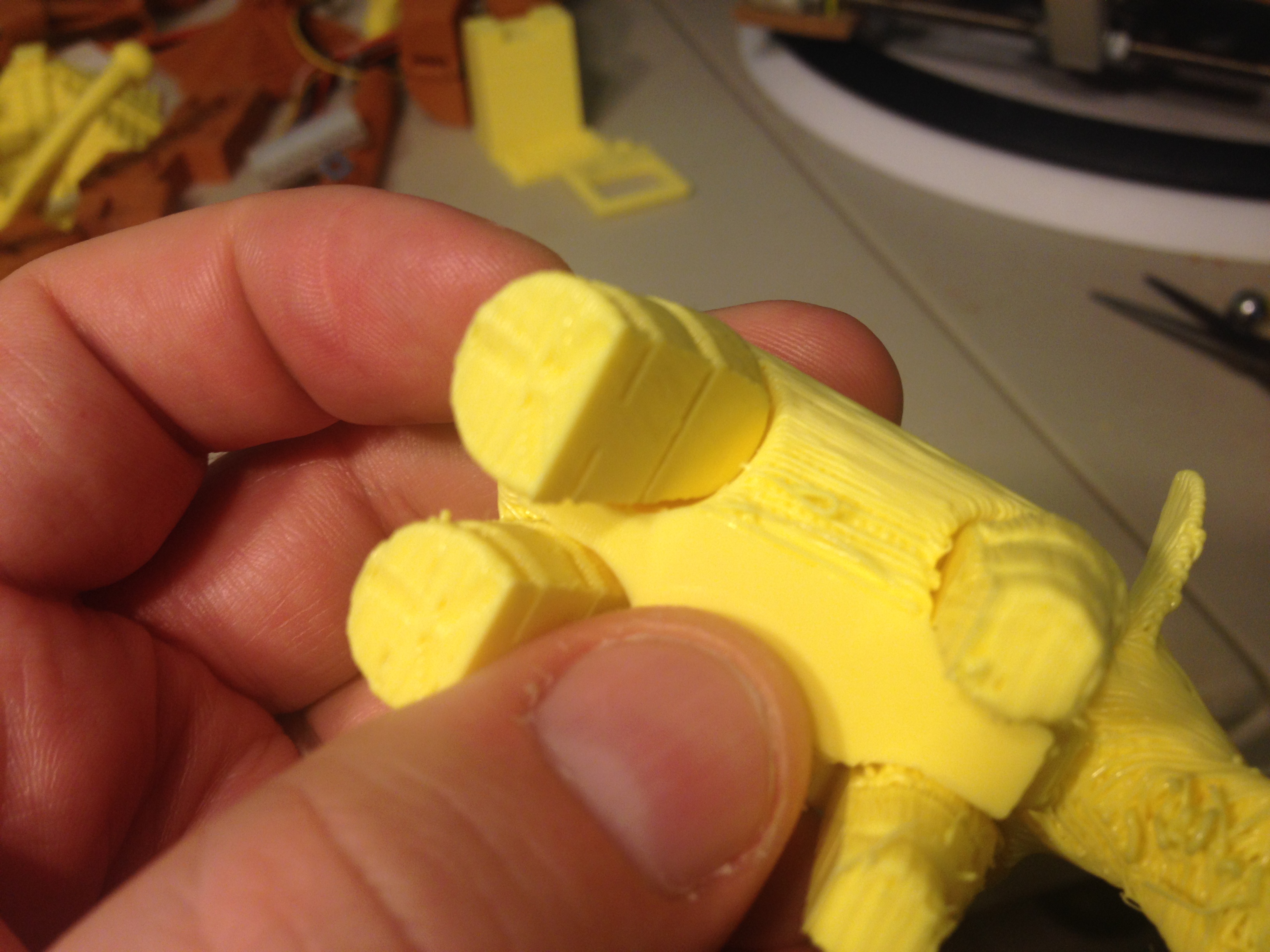
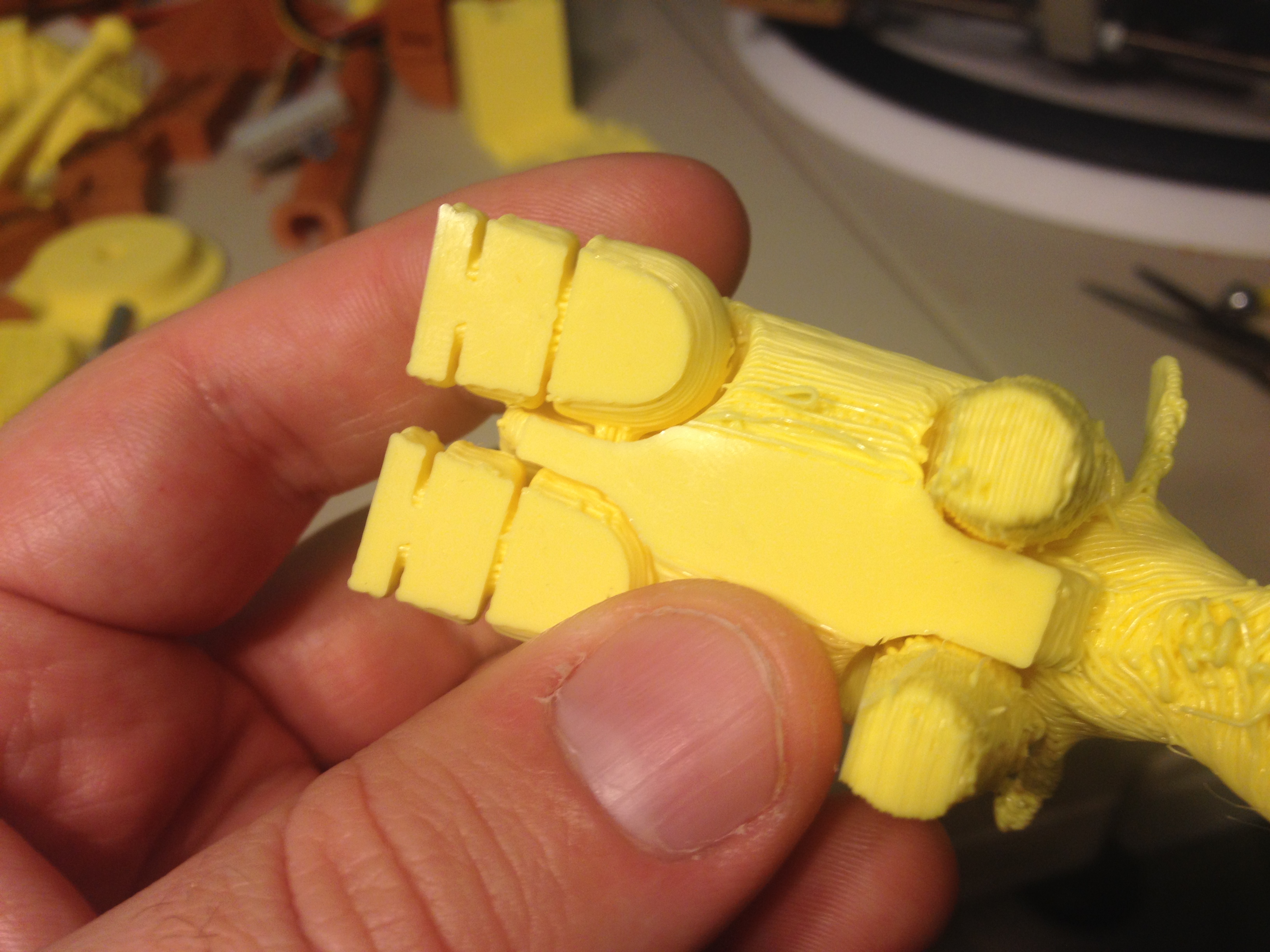
Monarch Glider, Stanford Bunny, REDO: PL1Q Vampire Arm – February 16, 2014
I wanted to give a risky print a try, so I printed the Monarch Glider (which I did throw once or twice, but didn’t have much grace..). Then again, I might have just been timid about breaking one of the things I printed for #FFo3DP
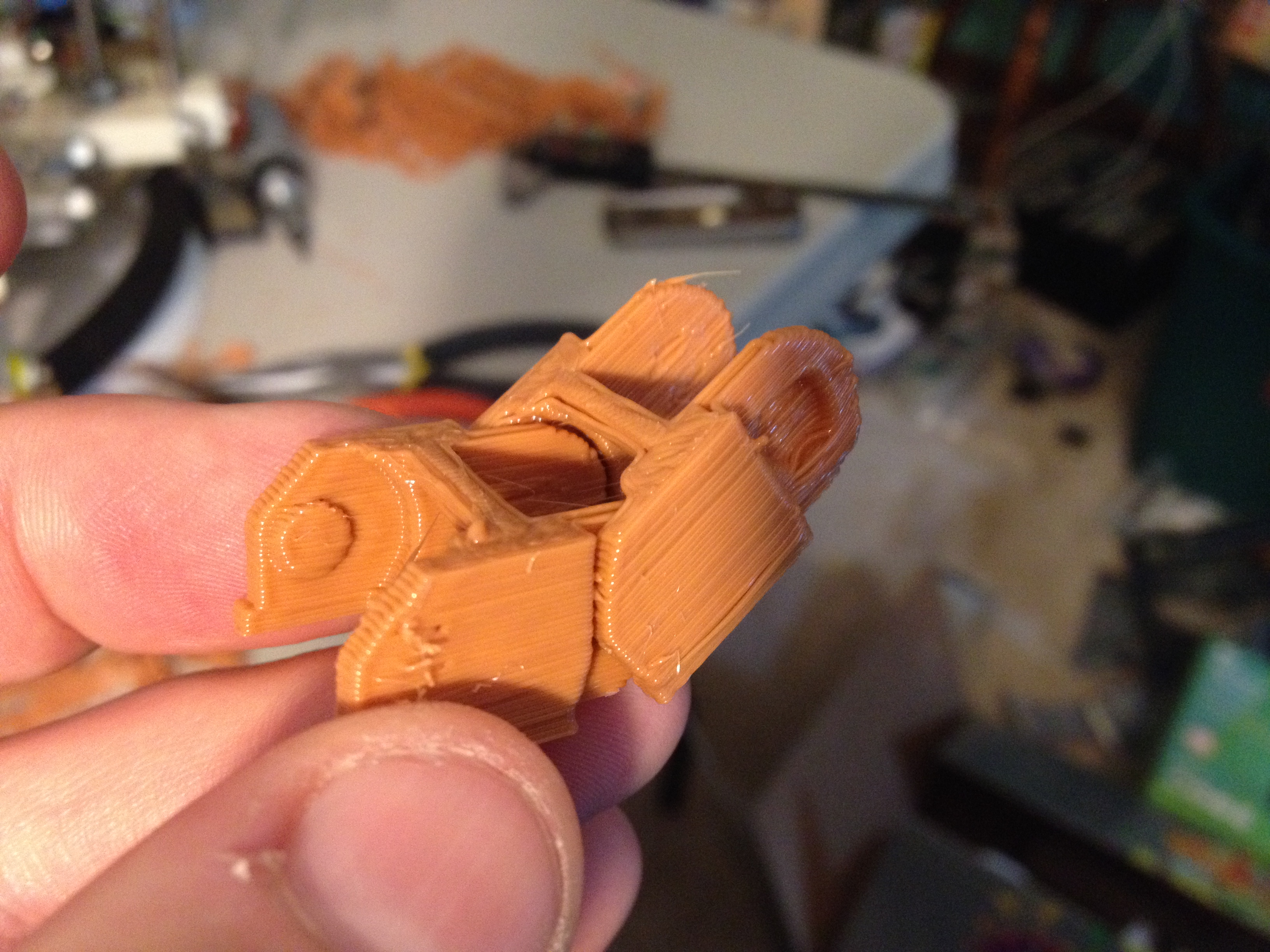
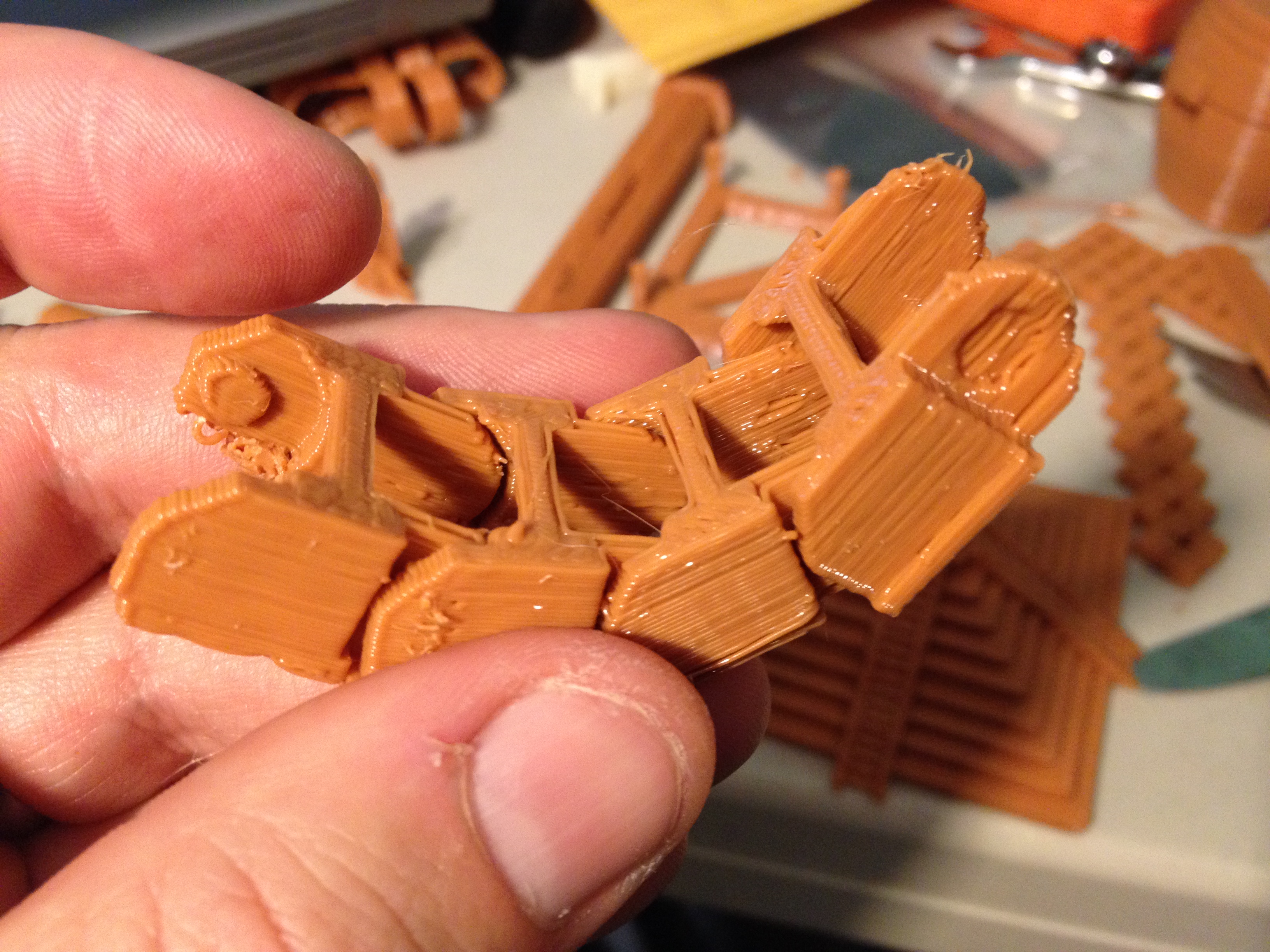
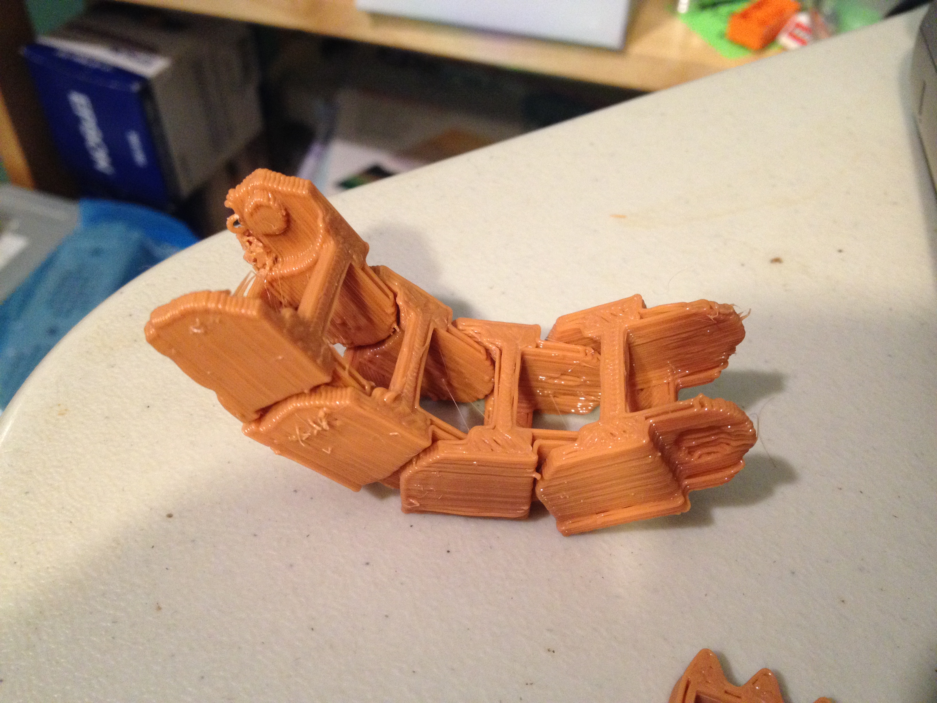
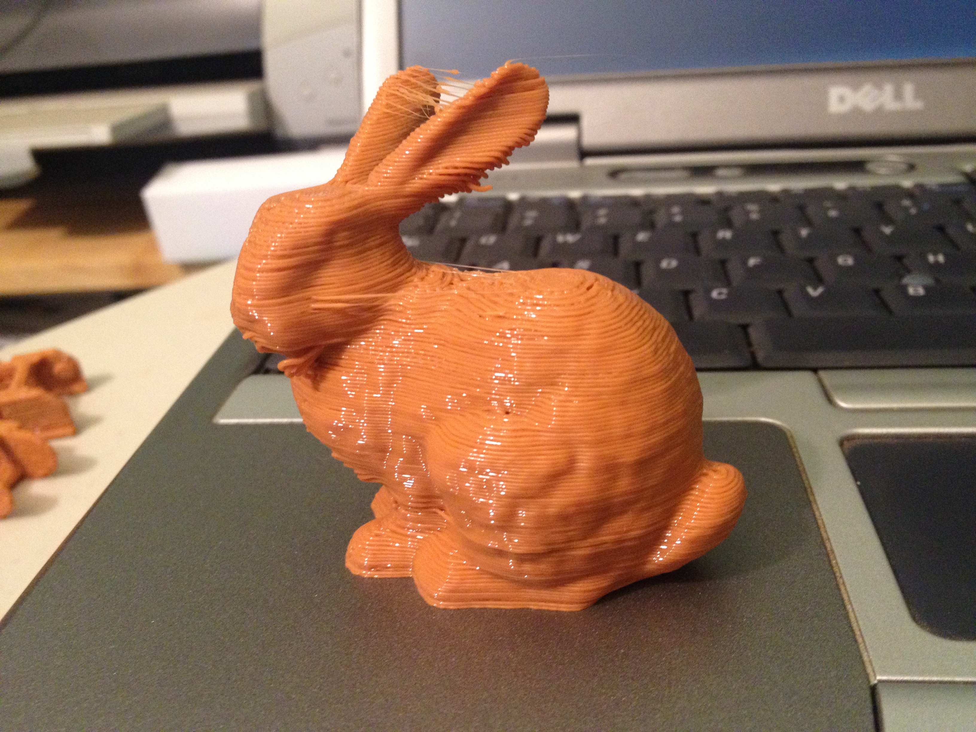
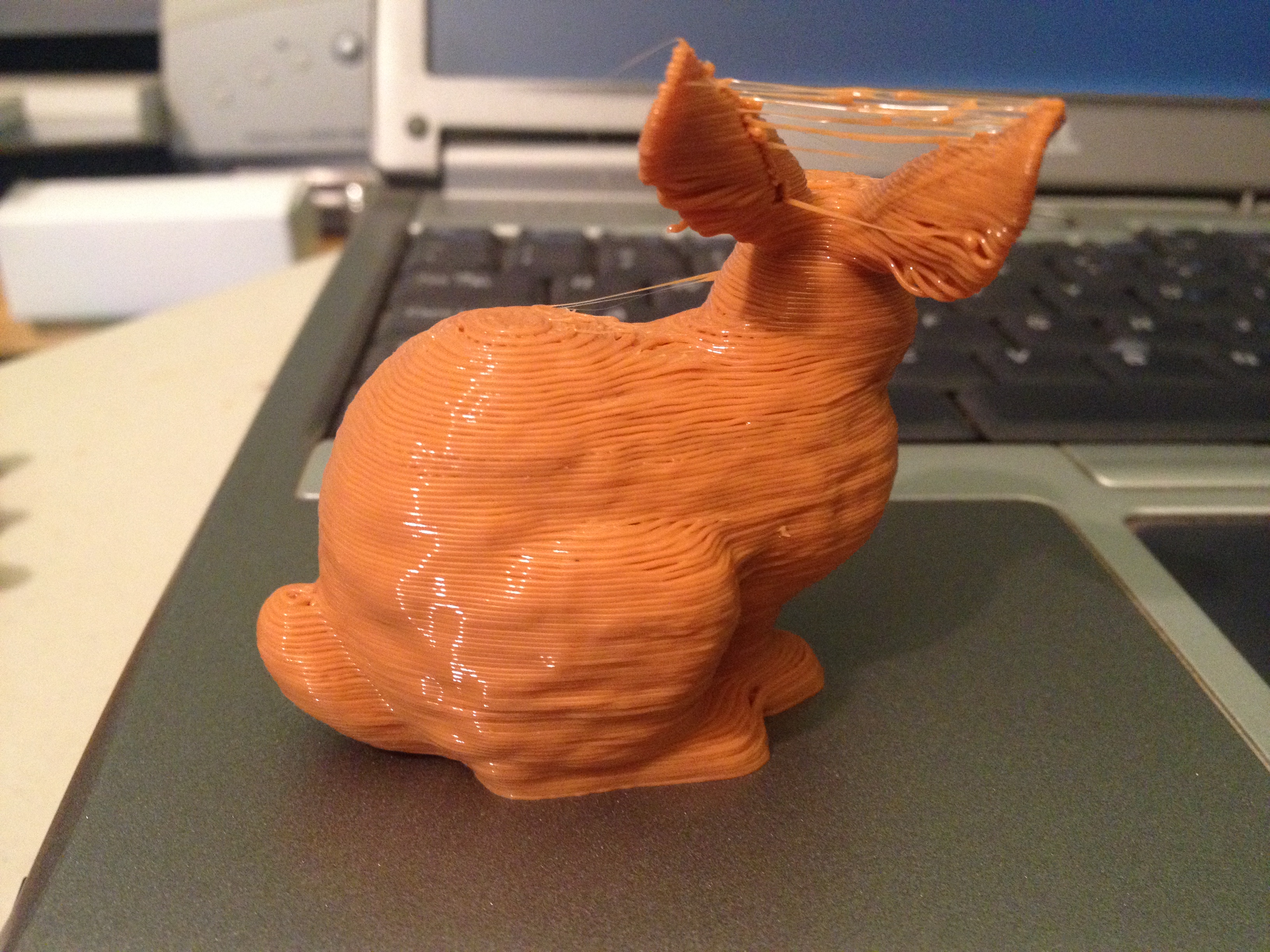
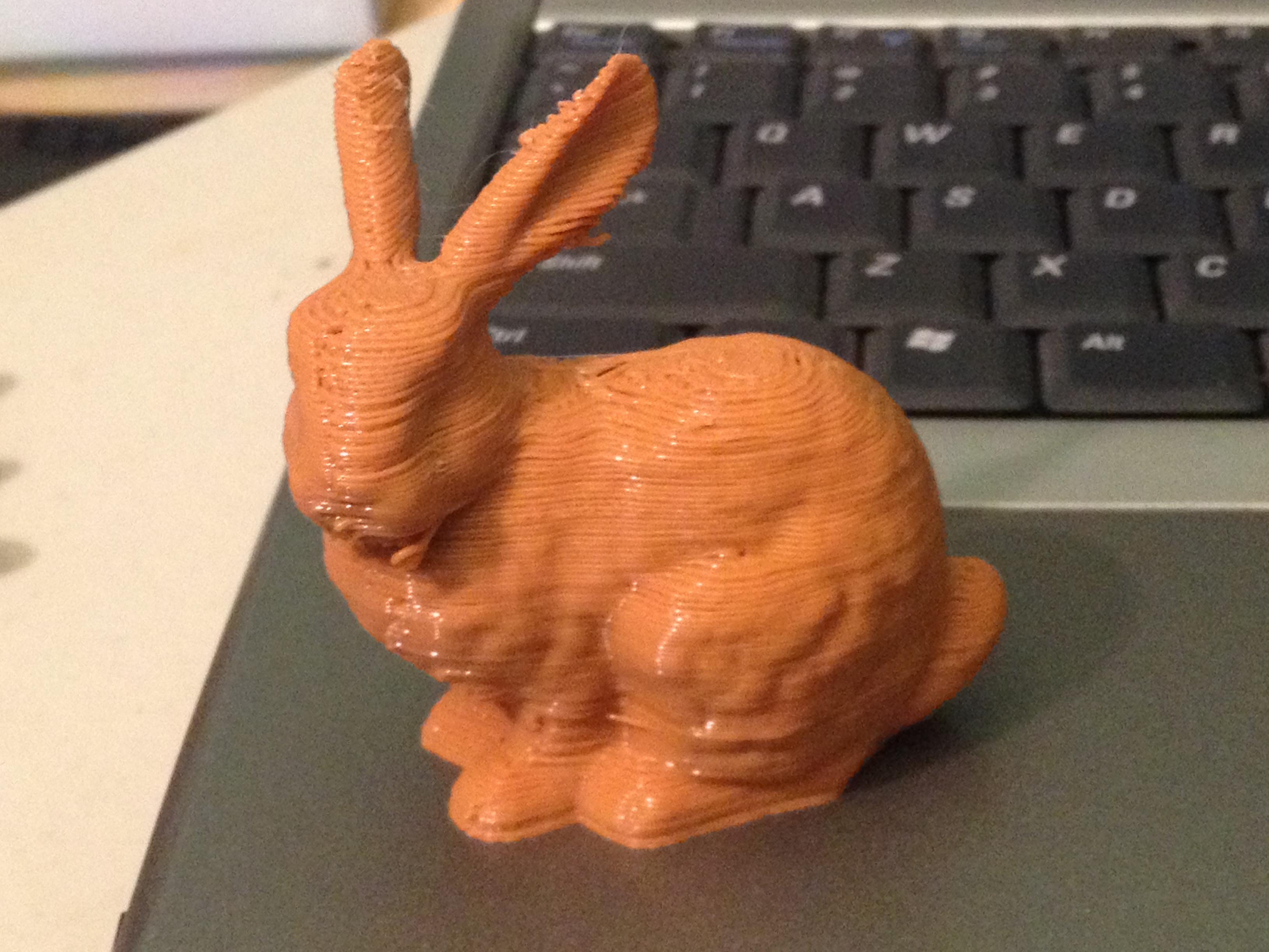
Since that turned out just okay, I decided to print another classic. I figured I’d tackle the Stanford Bunny, which goes all the way back to 1994 as a computer graphics test model.. I wasn’t sure how well it would come out. Oh man..
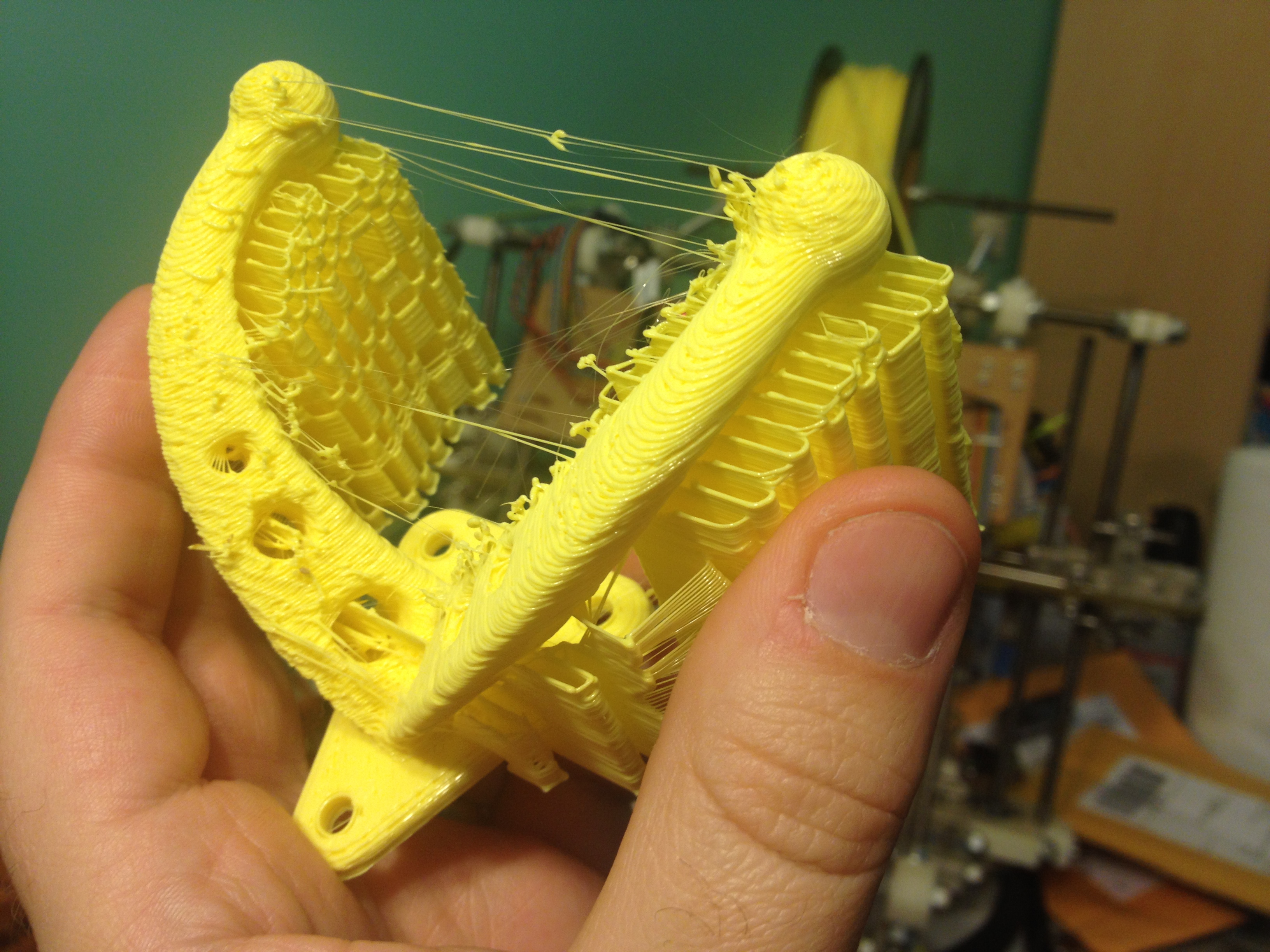
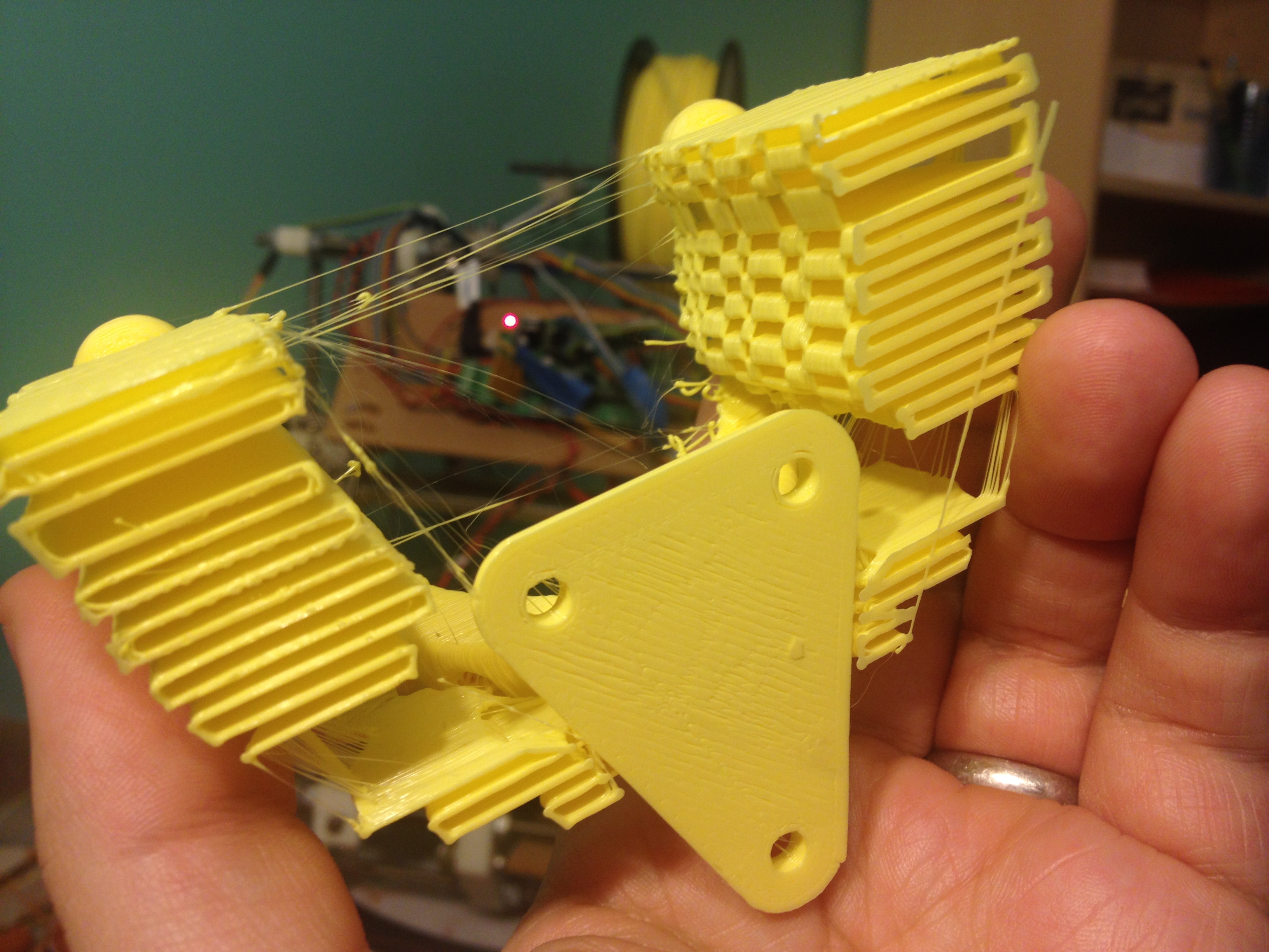
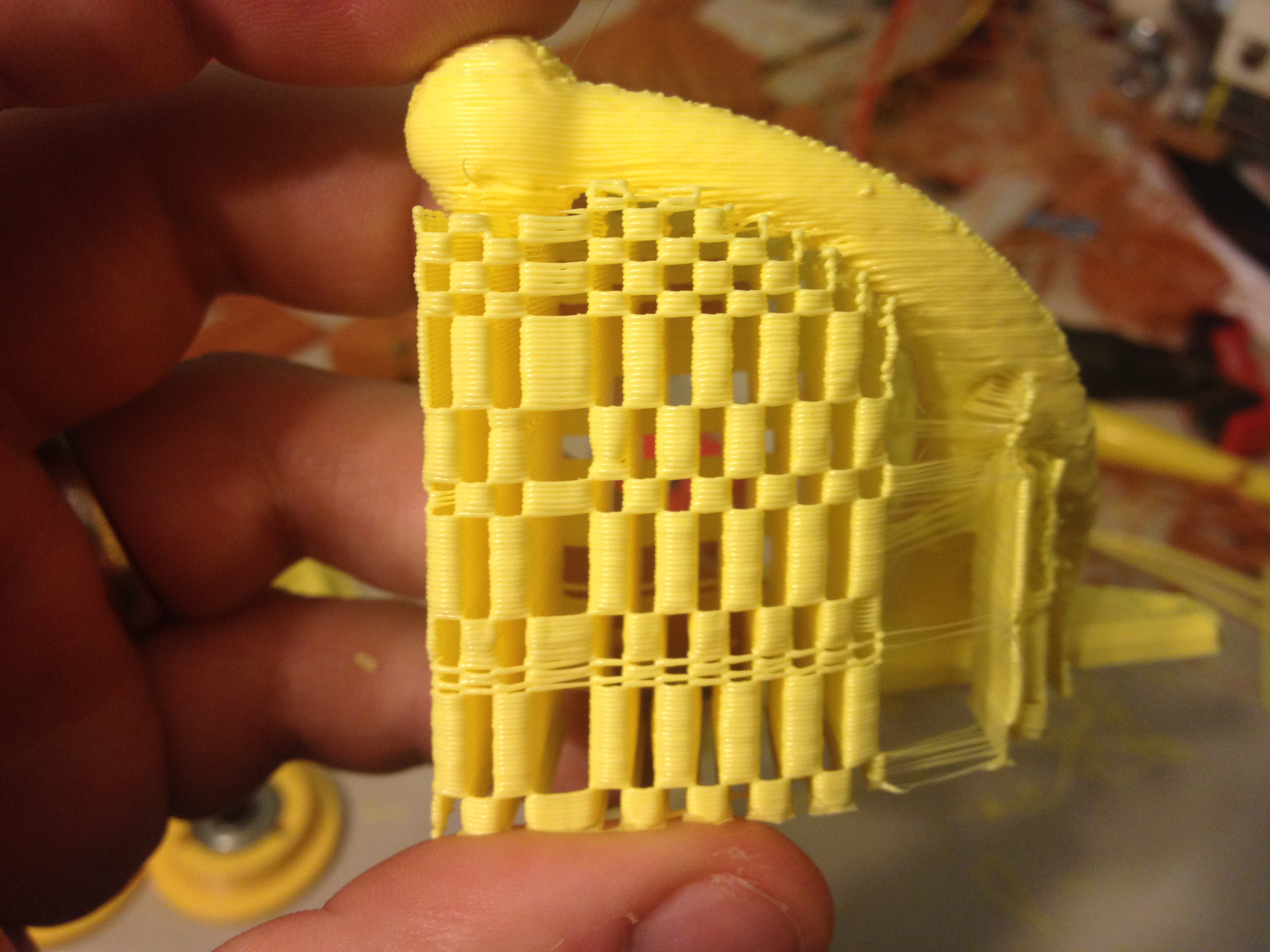
This day I also made another attempt at printing a quadcopter arm from the first day..
I realized that I’d been using the old gcode and that’s why it had failed on the earlier attempt.
Here’s a comparison with the failed one:
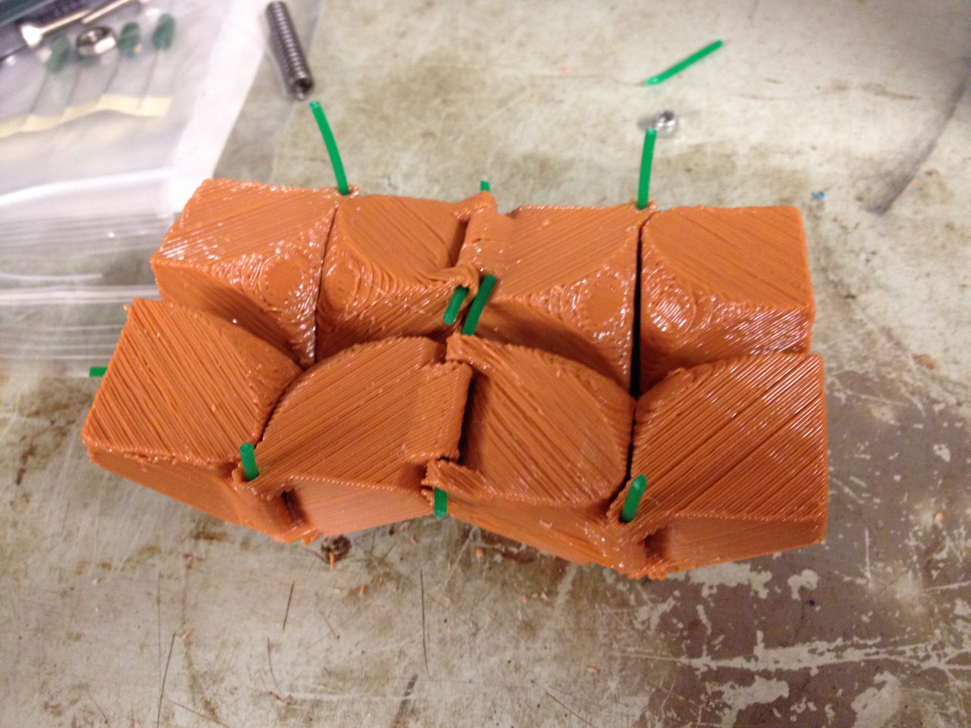
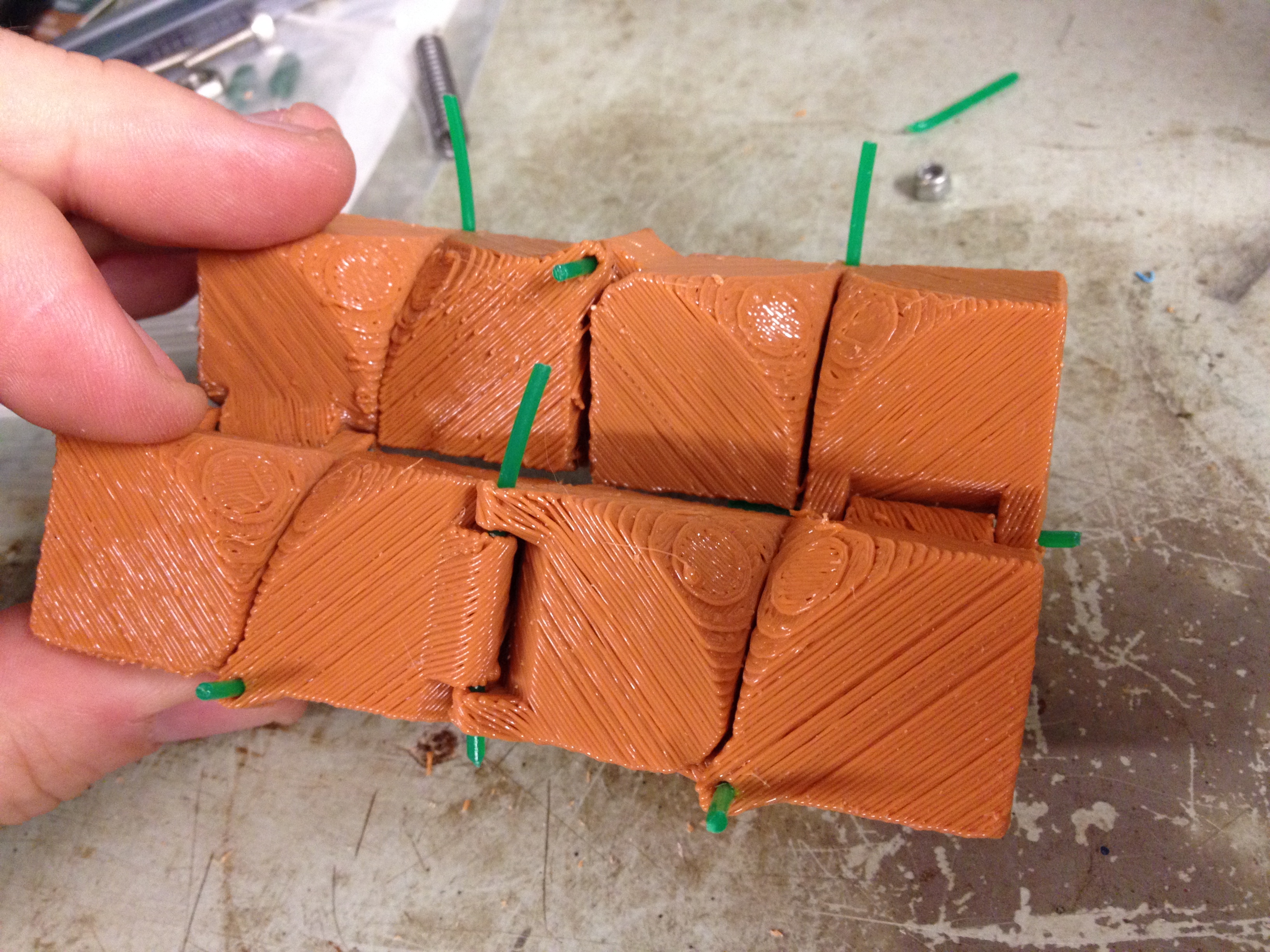
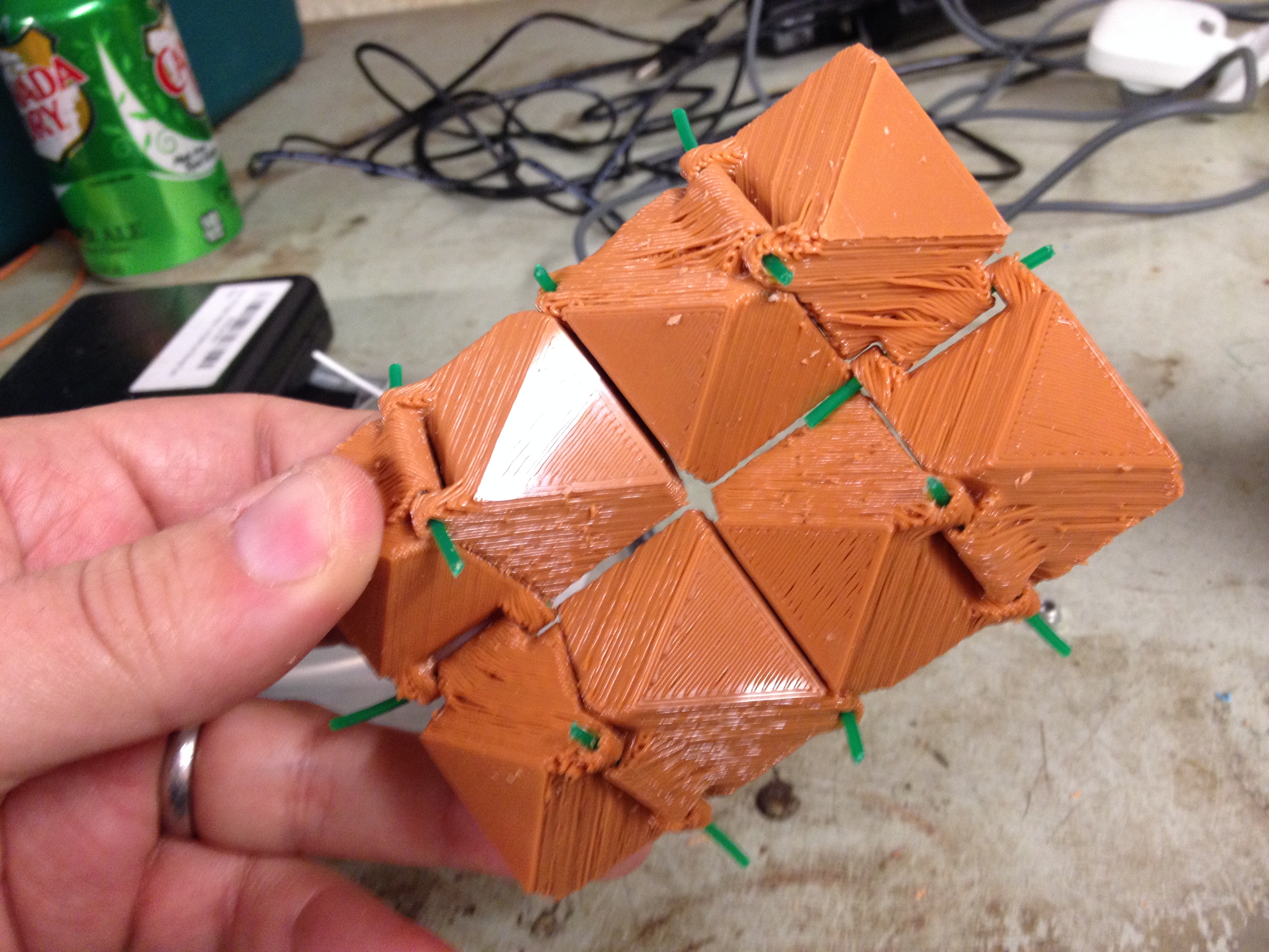
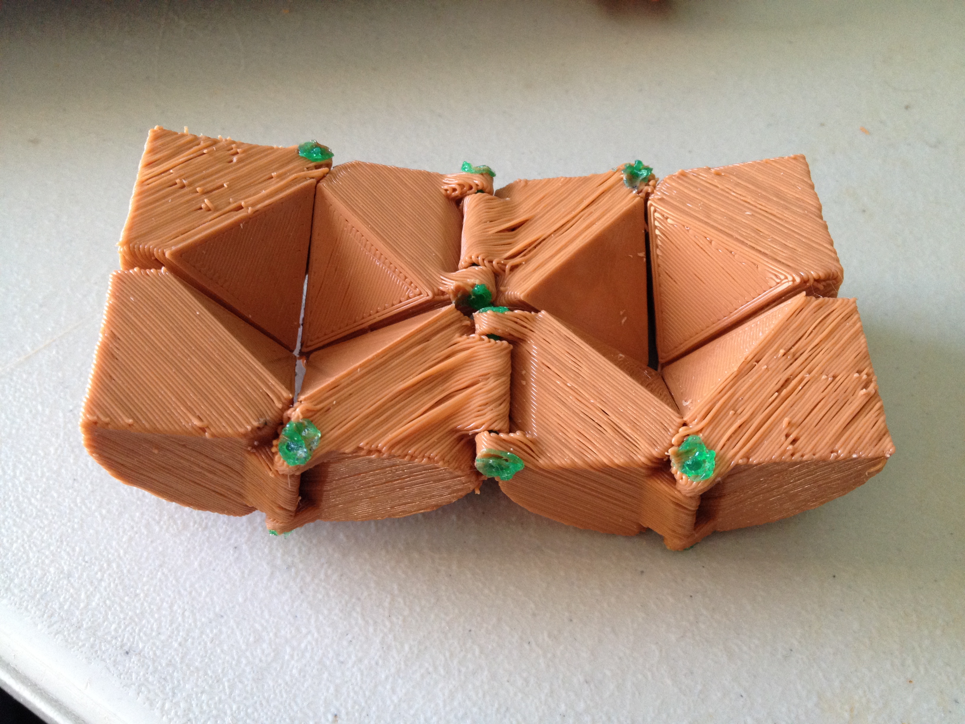
More durable folding cube with hinge pins – February 17, 2014
At work I had made several attempts to print Folding Cube by emmett, but the hinges always ended up breaking. So instead I wanted to try this variant, More durable folding cube with hinge pins. Instead of printing a hinge, you drill out the holes where the hinges would be to make them extra smooth, slide in some unused filament, and then melt the ends of that filament with a soldering iron (or extruder tip) to keep them from sliding out. It worked extremely well – it’s now February 2015 and despite using it like crazy, this folding cube hasn’t failed yet.
Here is video of it actually folding:
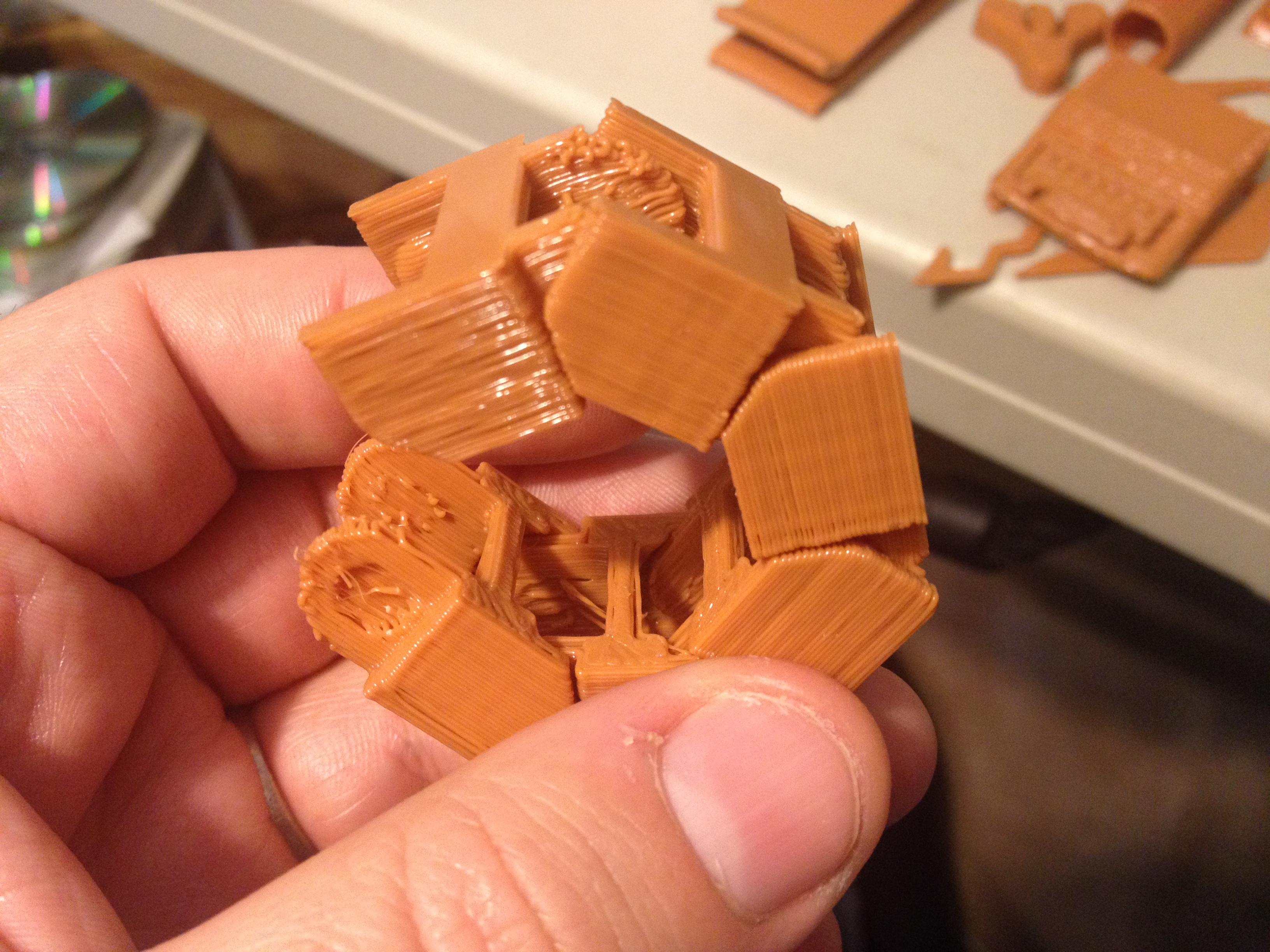
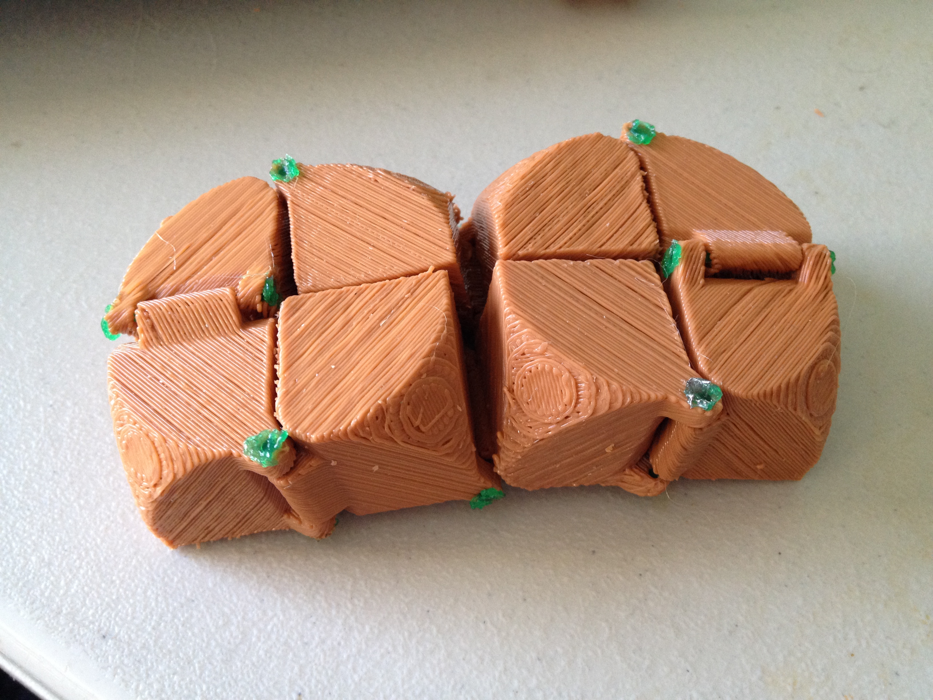
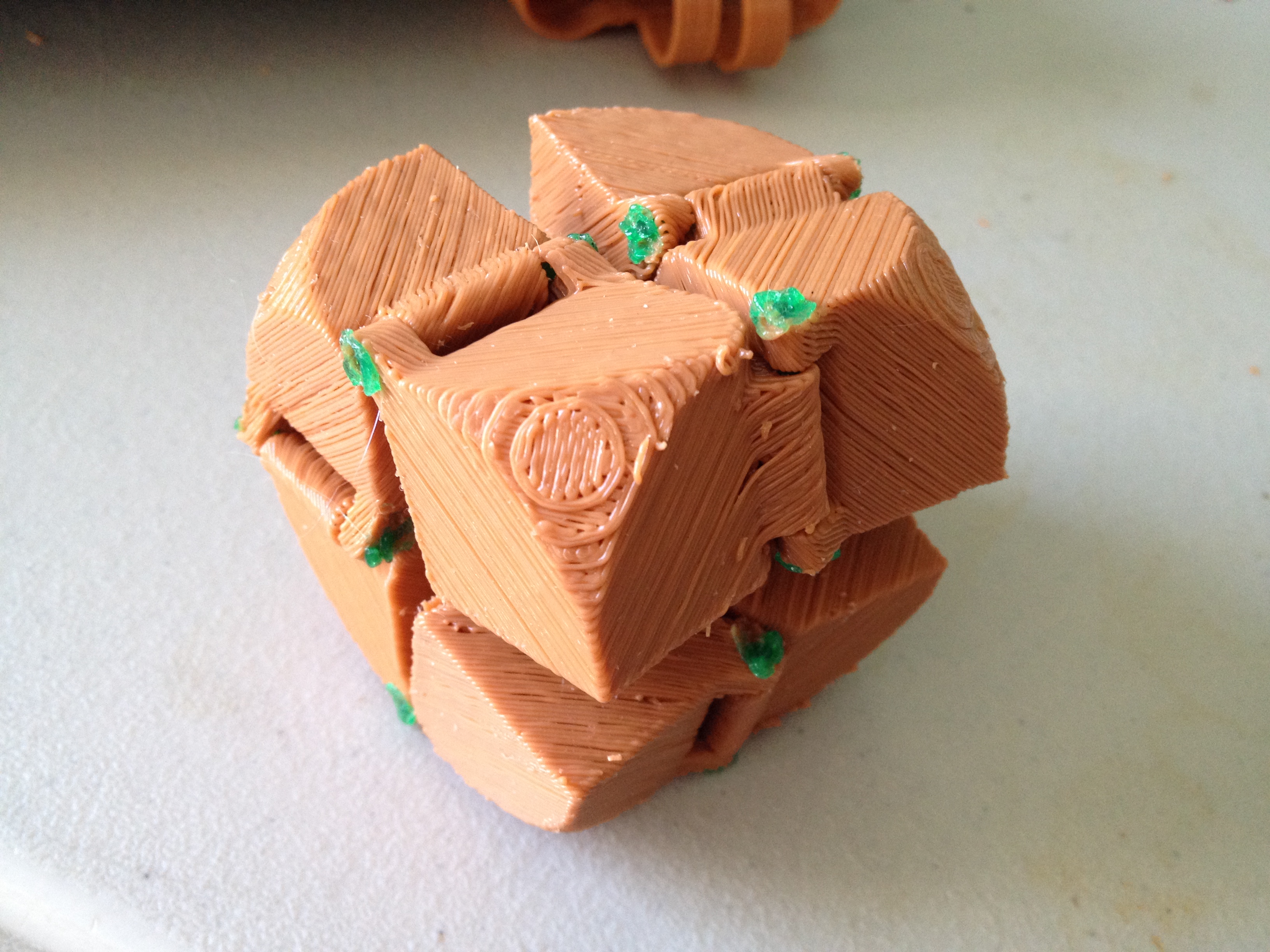
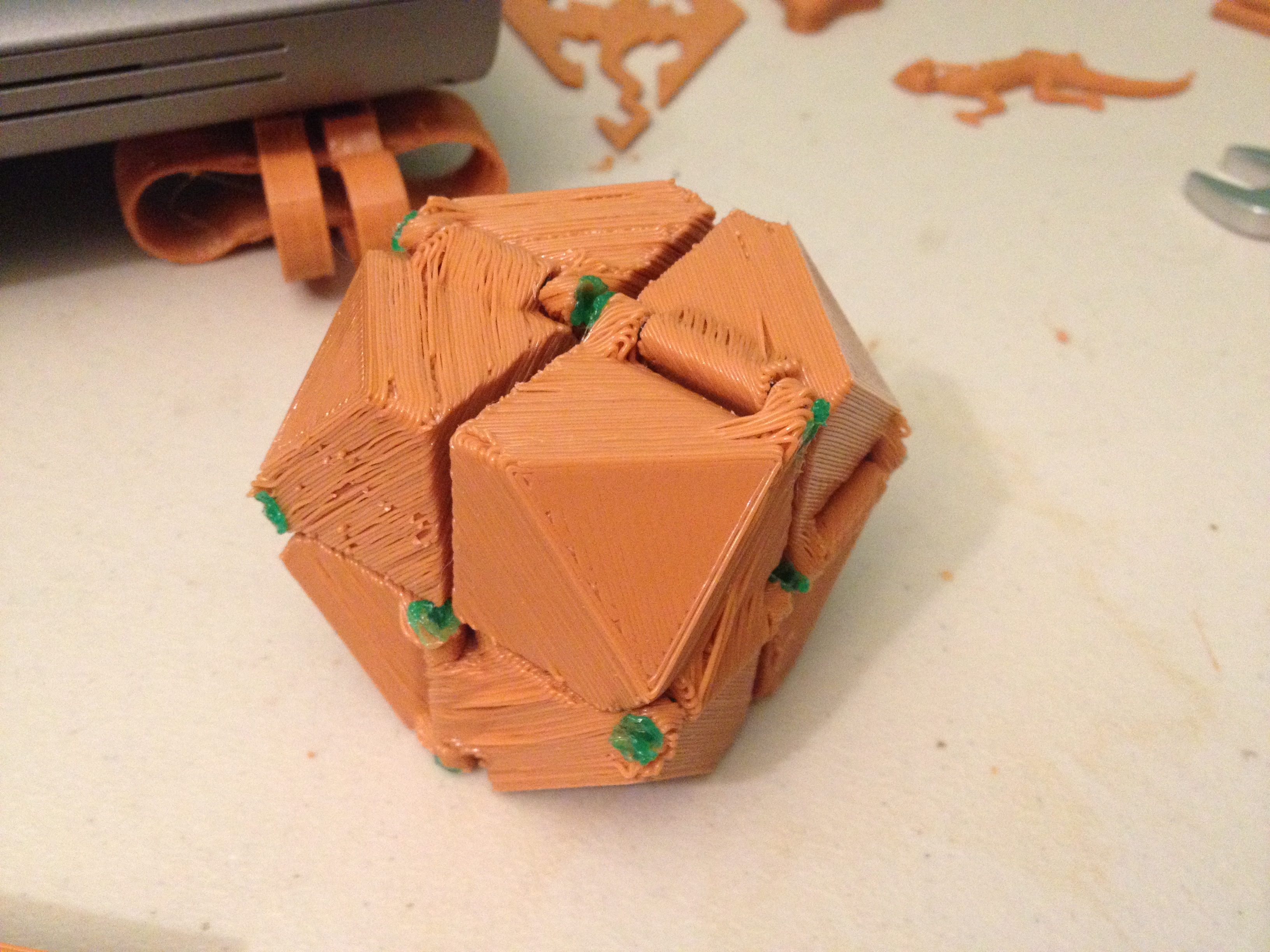
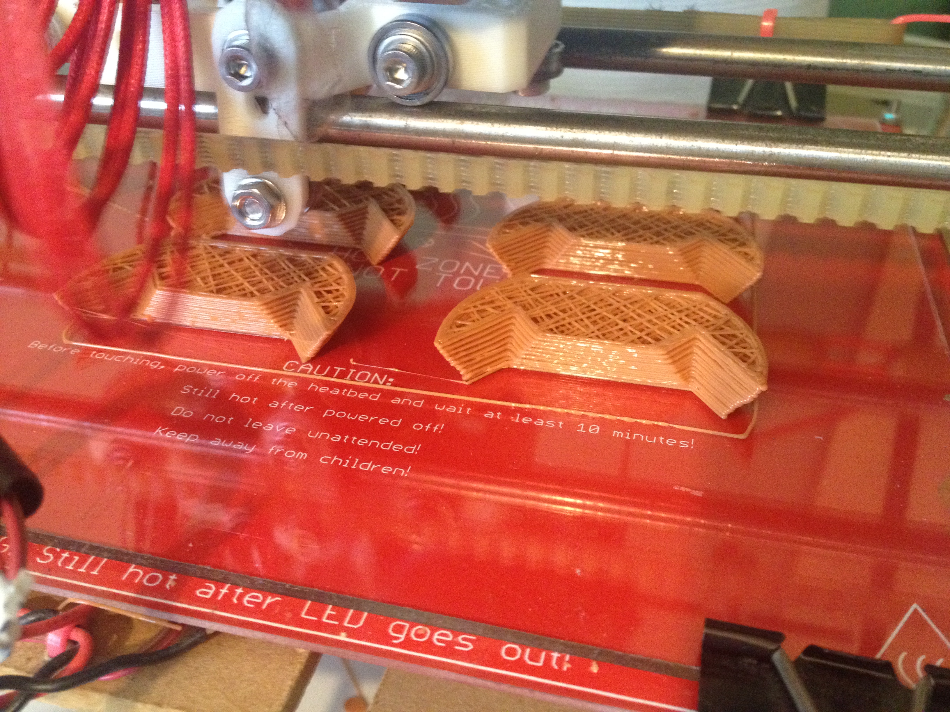
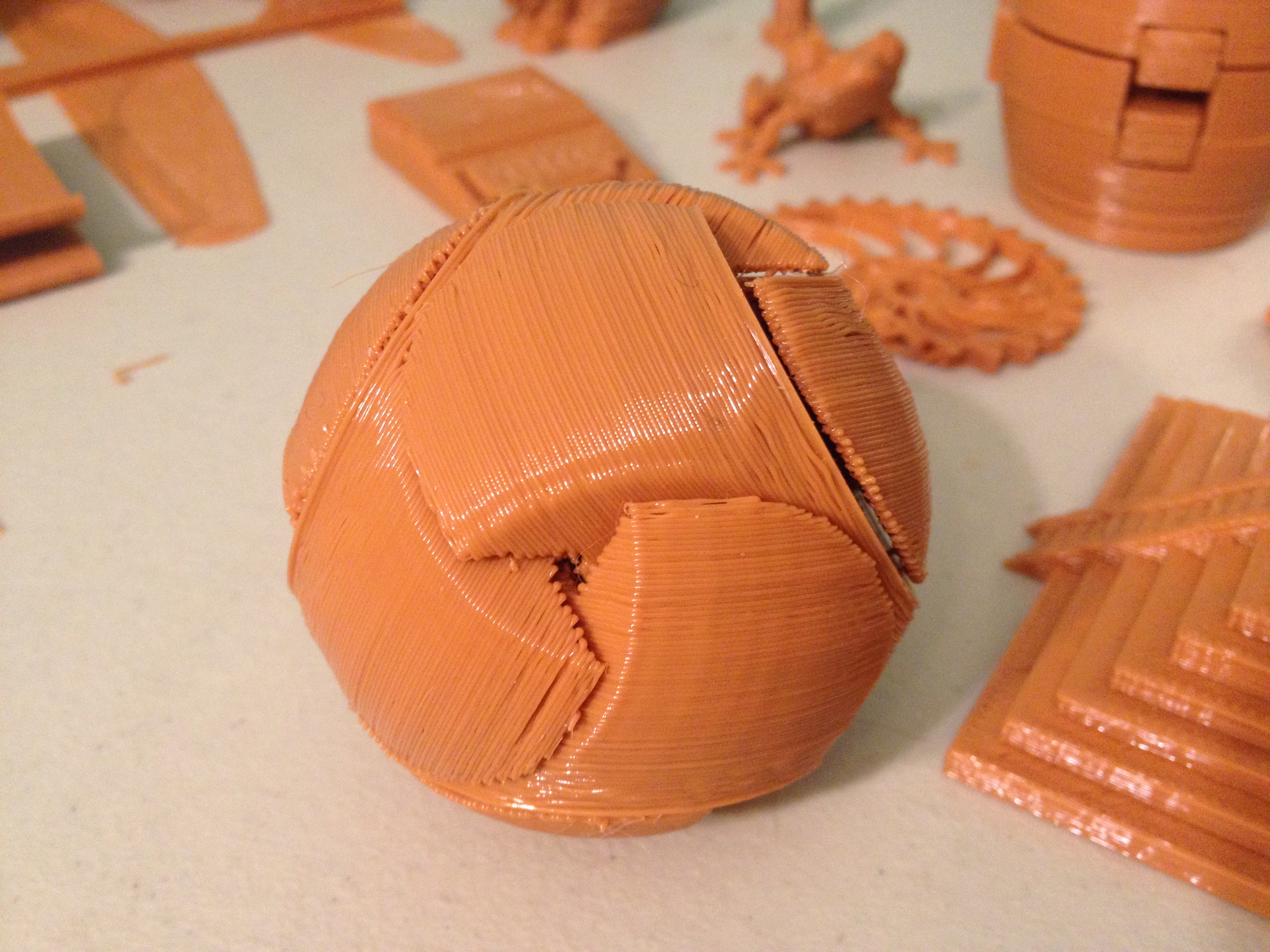
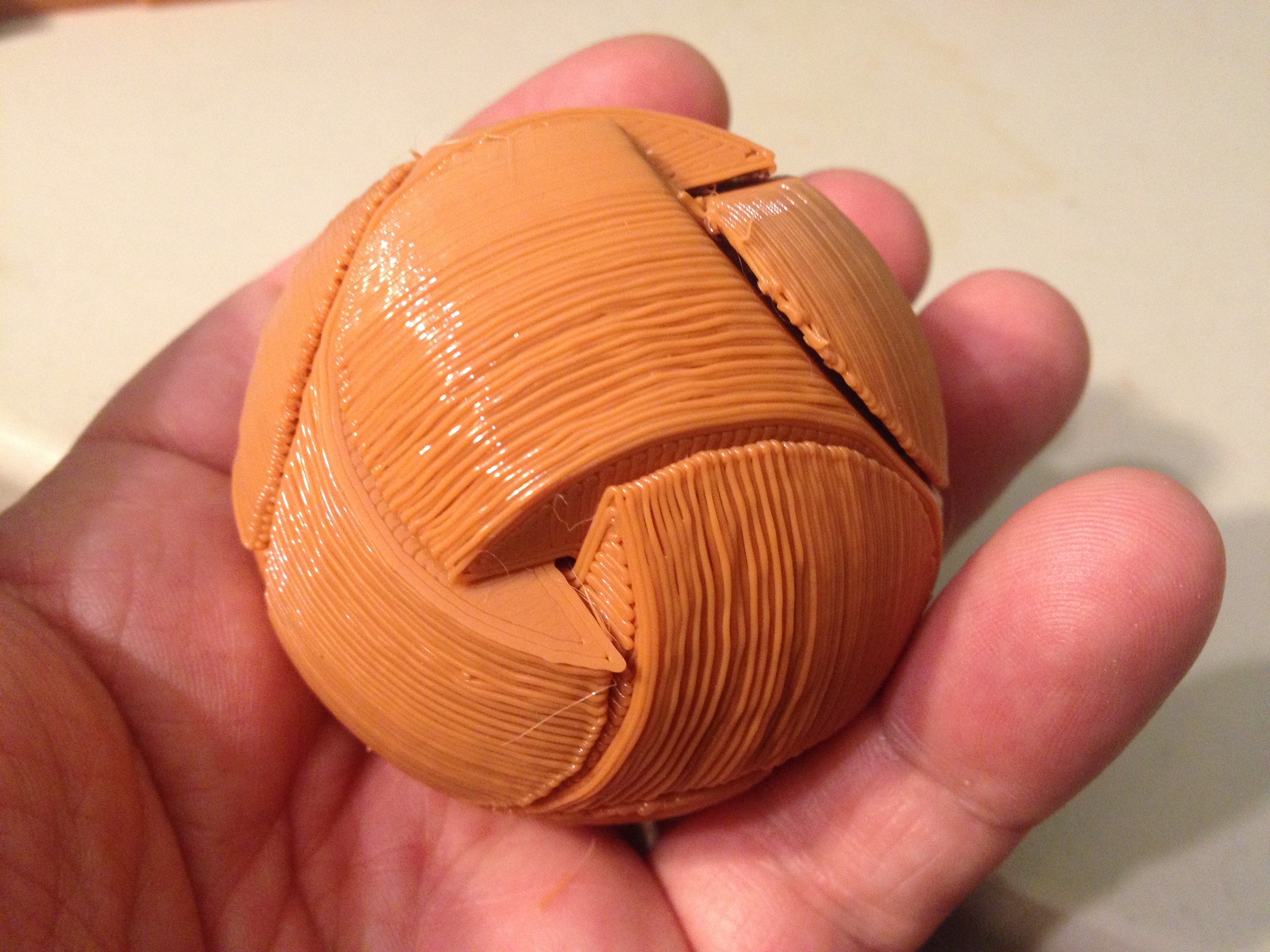
Puzzle Sphere – February 18, 2014
Next I printed a cool Puzzle Sphere that unlike its cousins doesn’t have a different “key” piece, but rather the pieces are all the same.
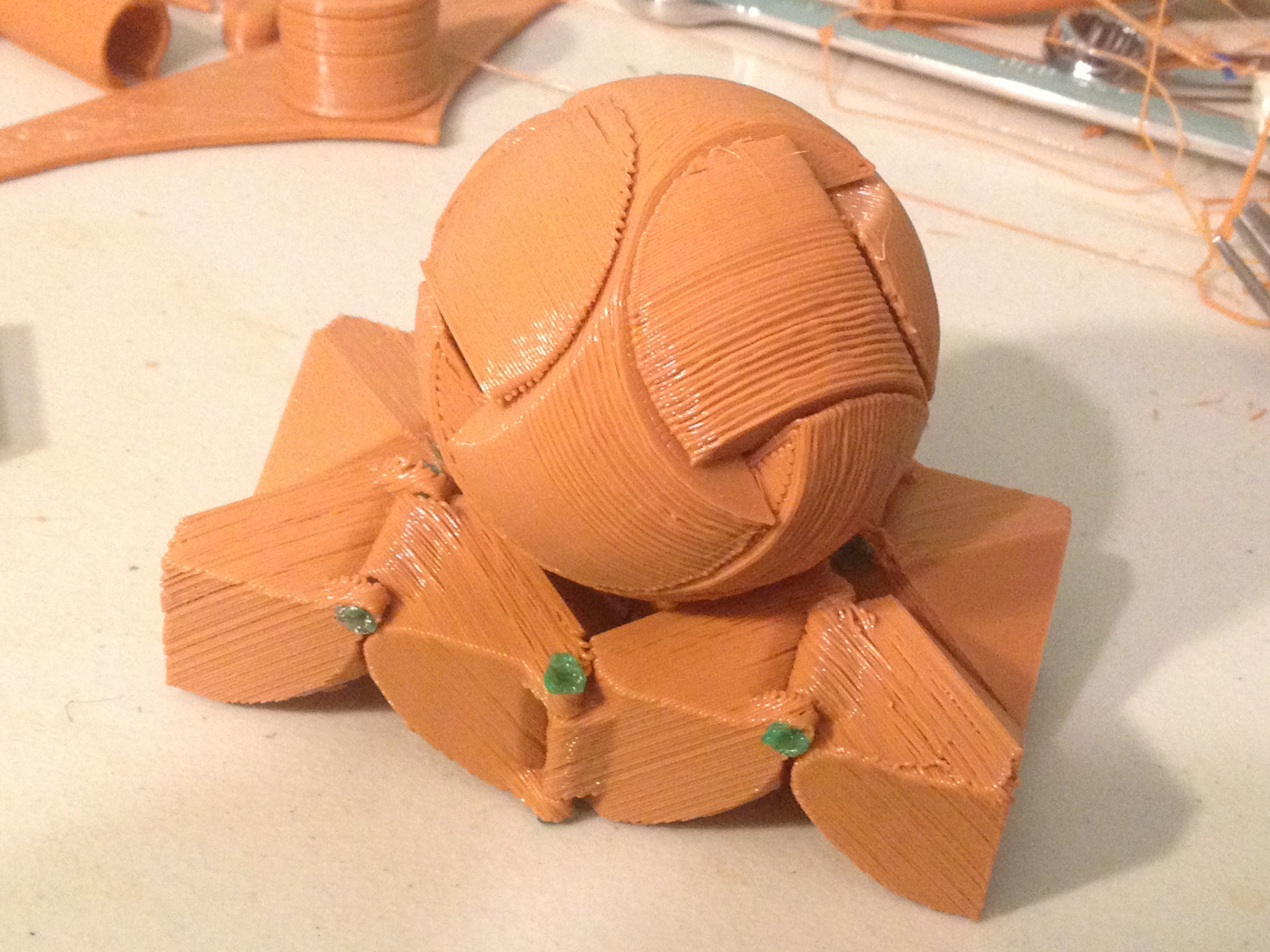
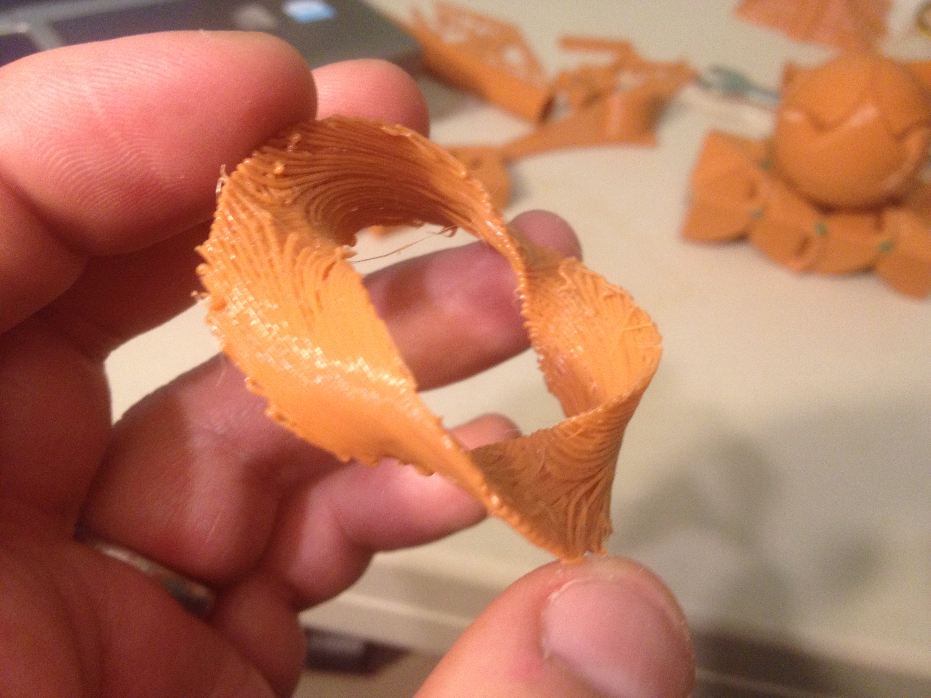
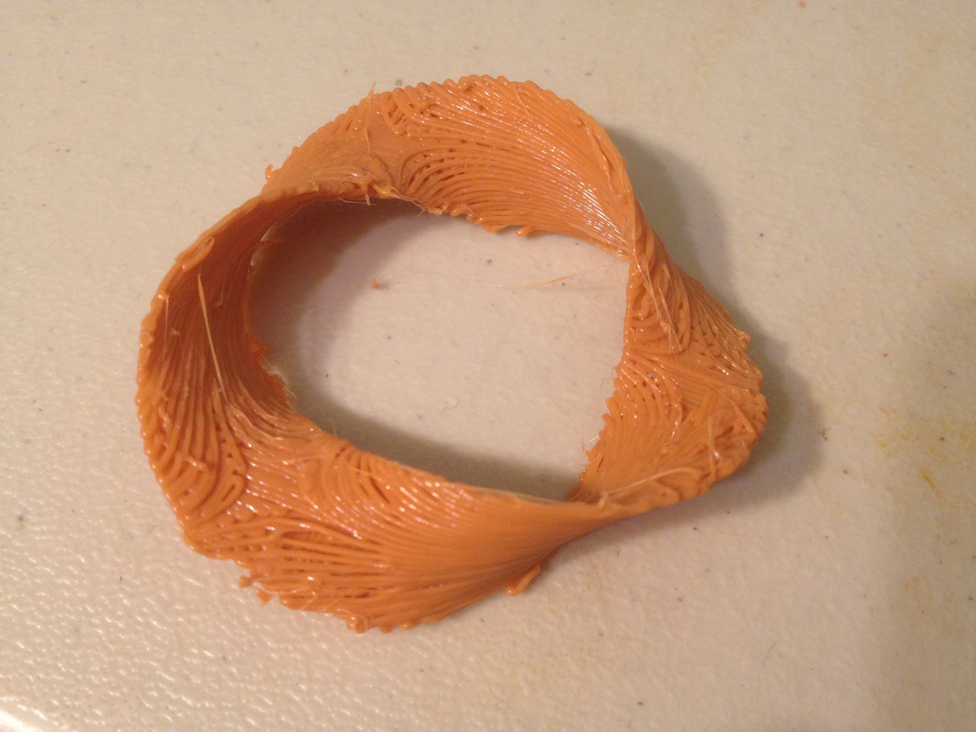
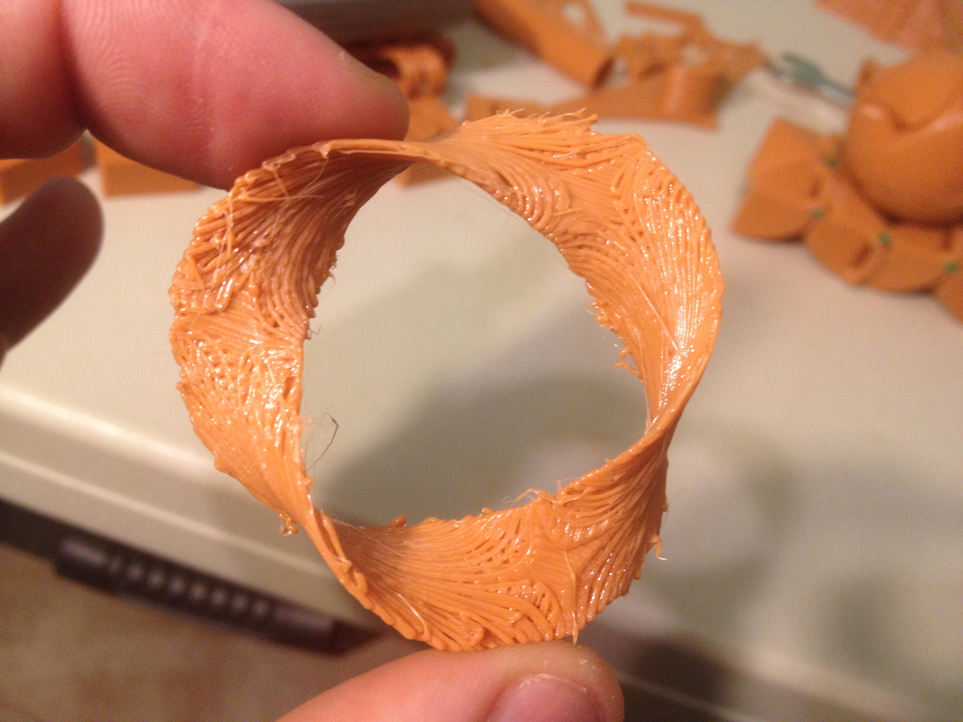
Mobius Surface – February 19, 2014
This one didn’t turn out great, but I did want to try it (and by this point, I was looking for things to print each day, and this was on my list). I printed a Mobius Surface (a shape with only one side), which required printing with support material.
Since I had free time, I also printed up a bunch more of the vibration dampeners from before:
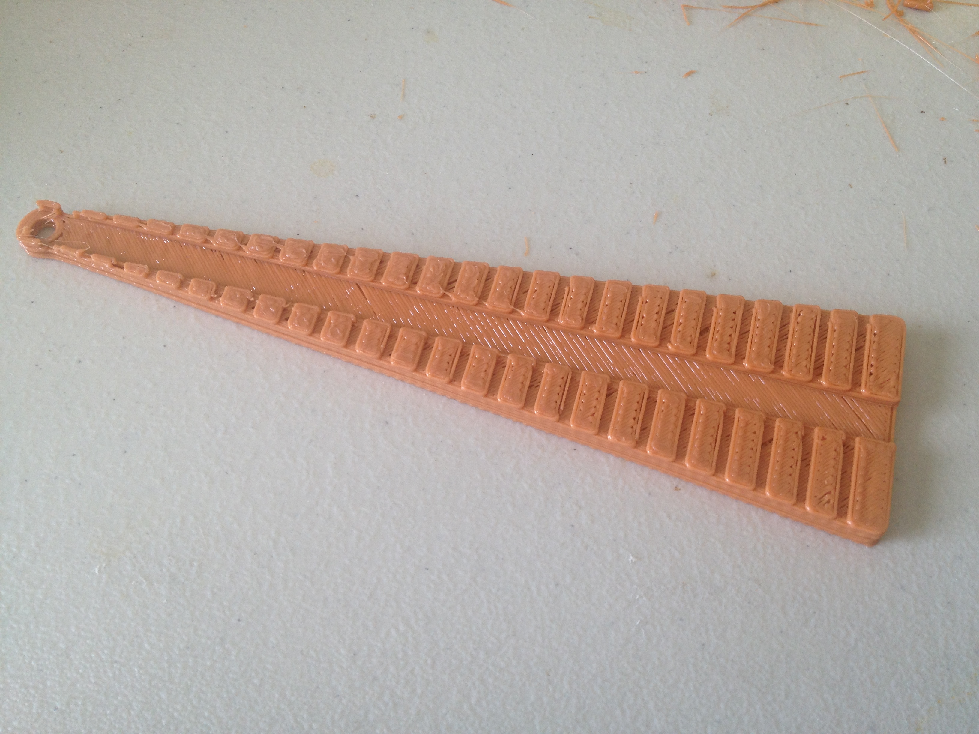
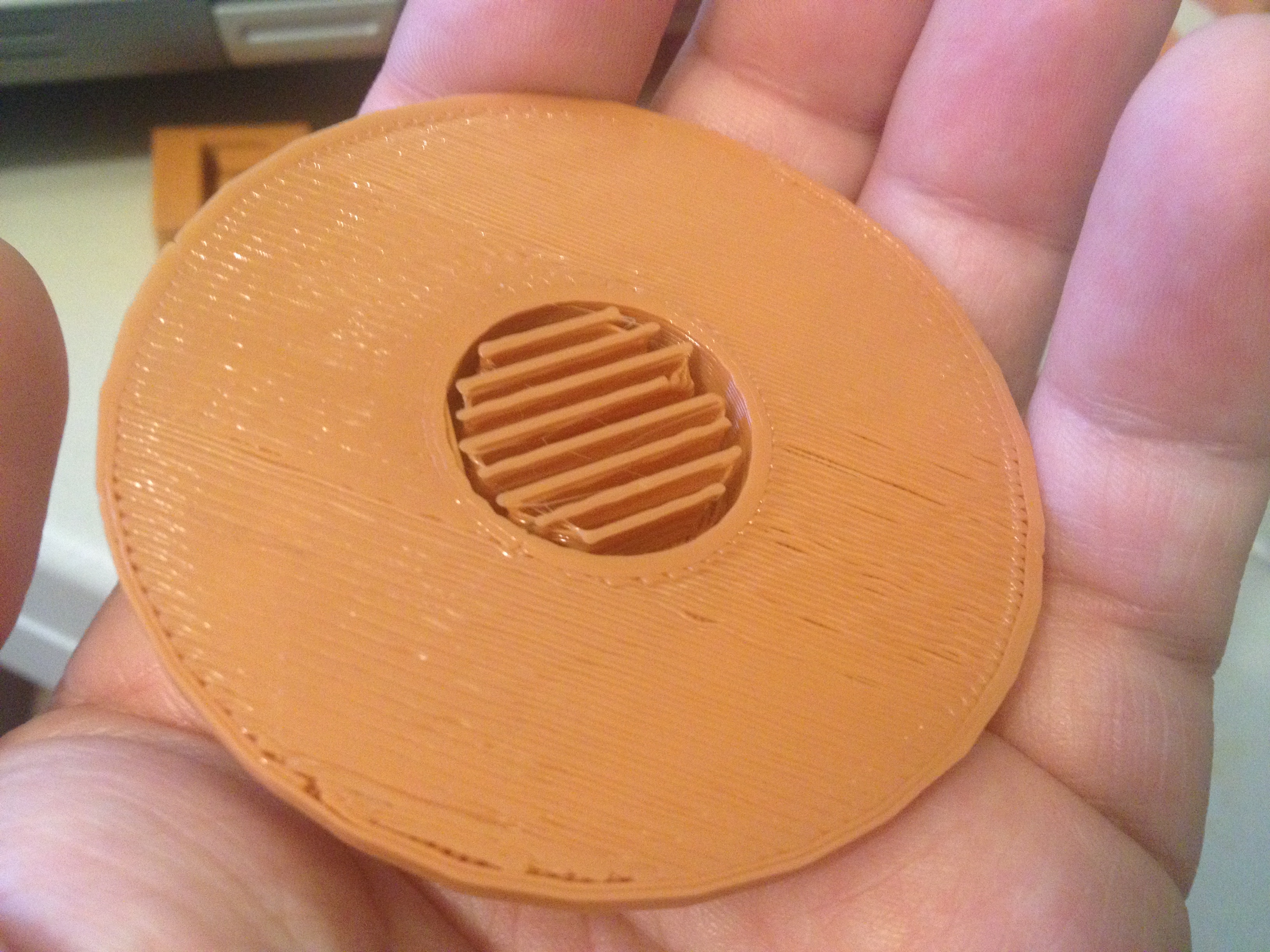
Resistor lead forming tool, Parametric ( Ultimachine 1Kg ) spool hub bearing, REDO: chichen_itza matrix building – February 20, 2014
Another simple looking object (which, again, was in high demand at the time, since I wanted objects I could reliably print each day) was this Resistor lead forming tool that lets you bend the leads of resistors to set widths suitable for insertion into a breadboard or circuit board:
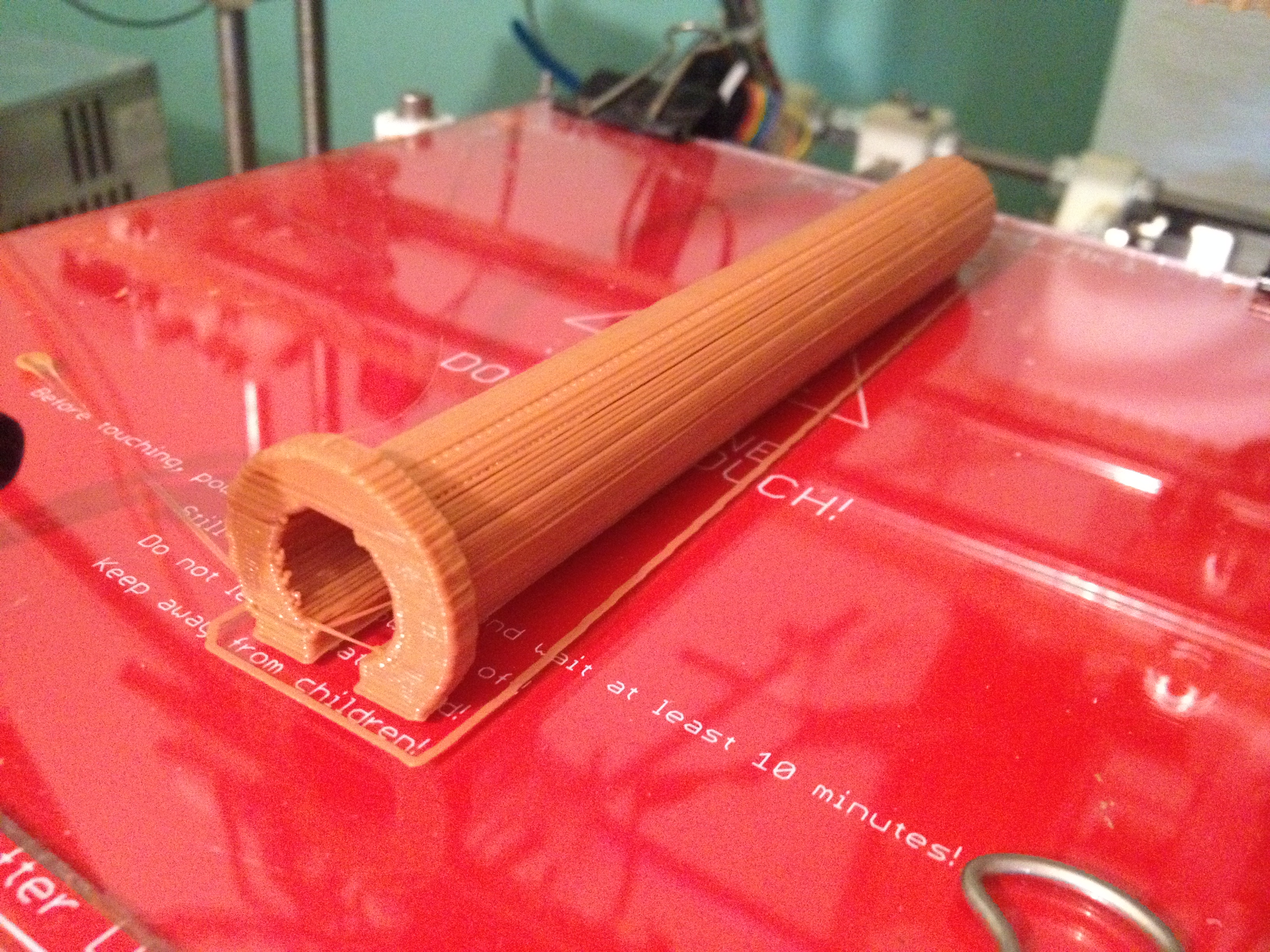
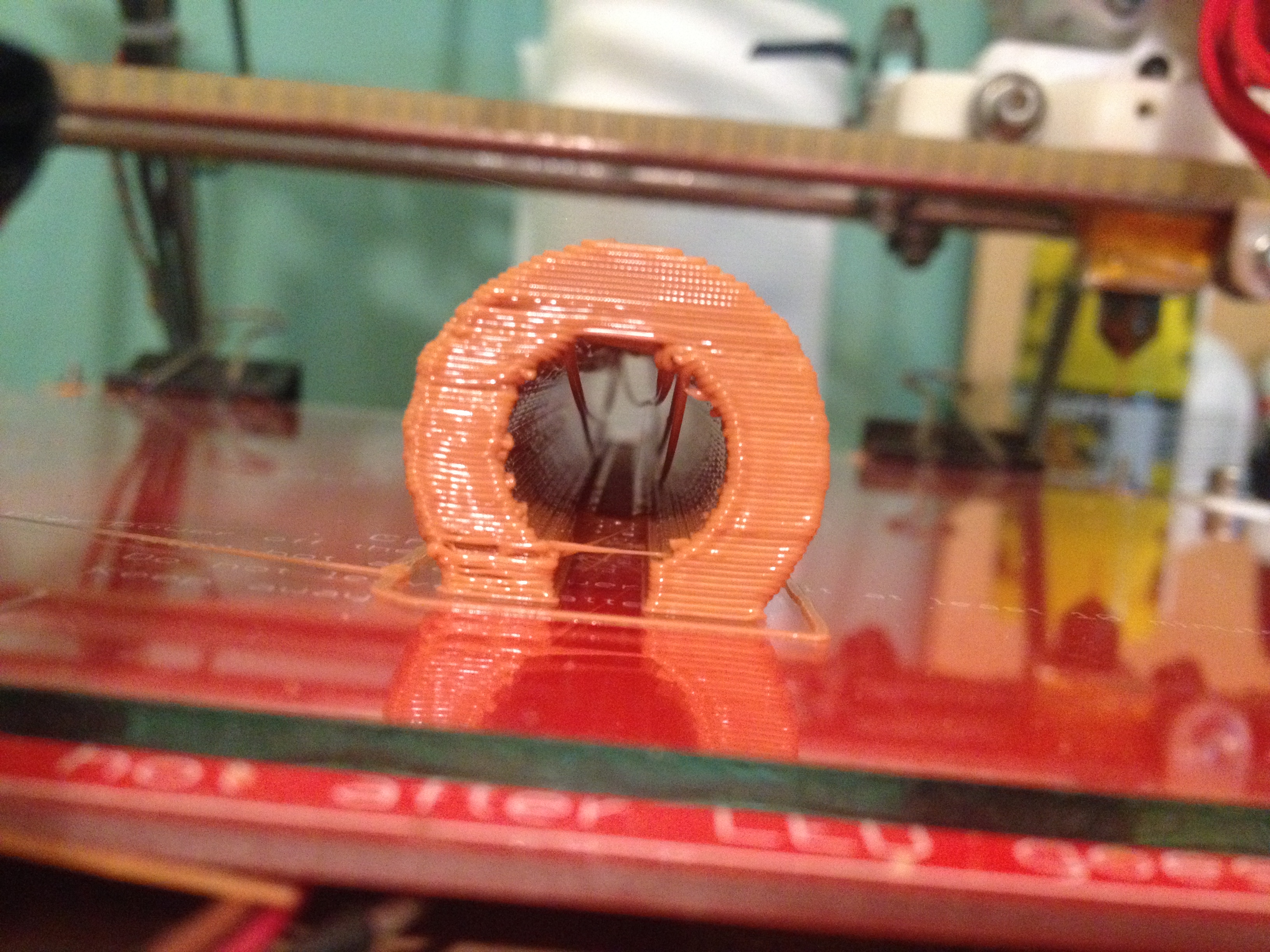
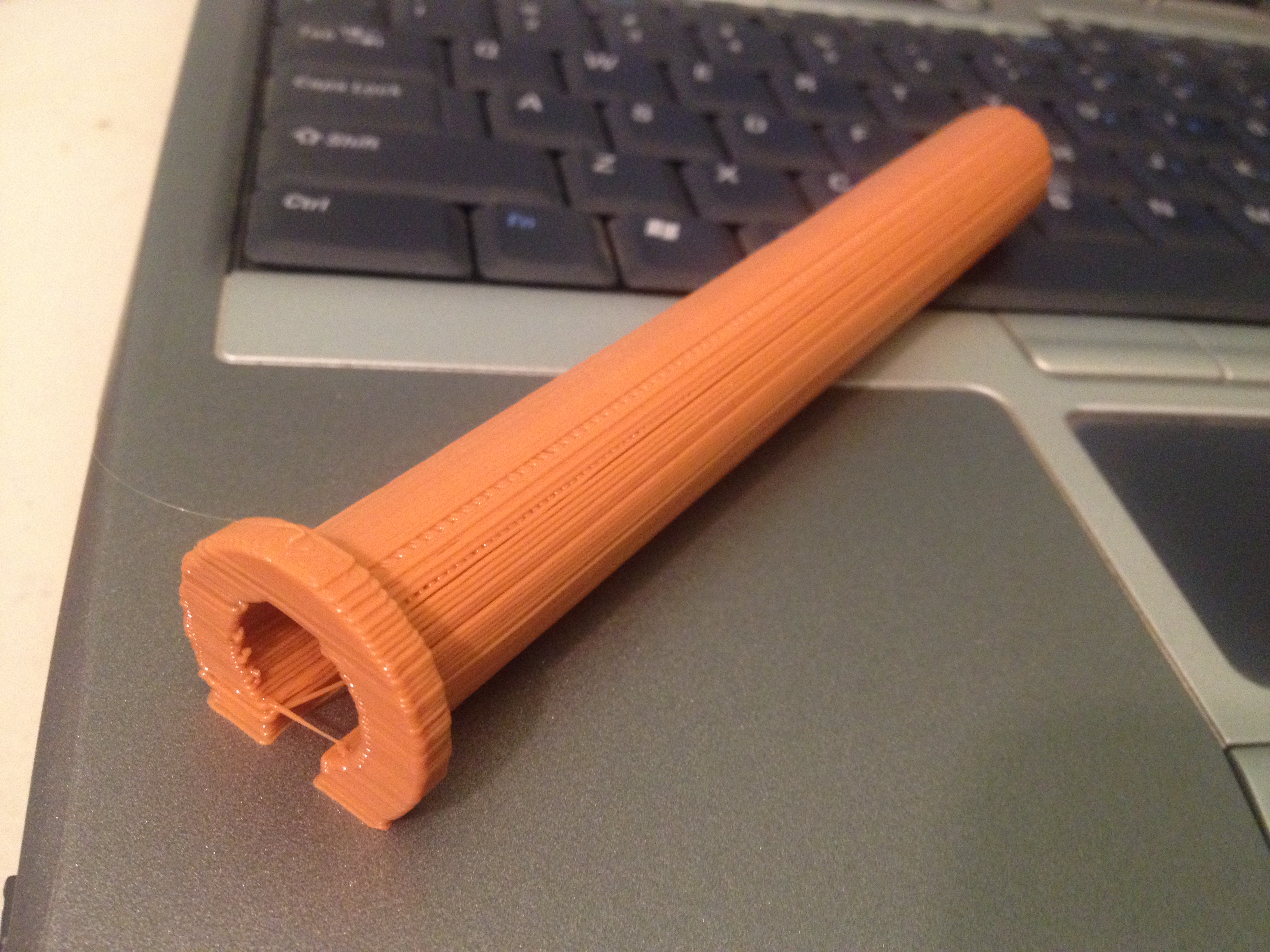
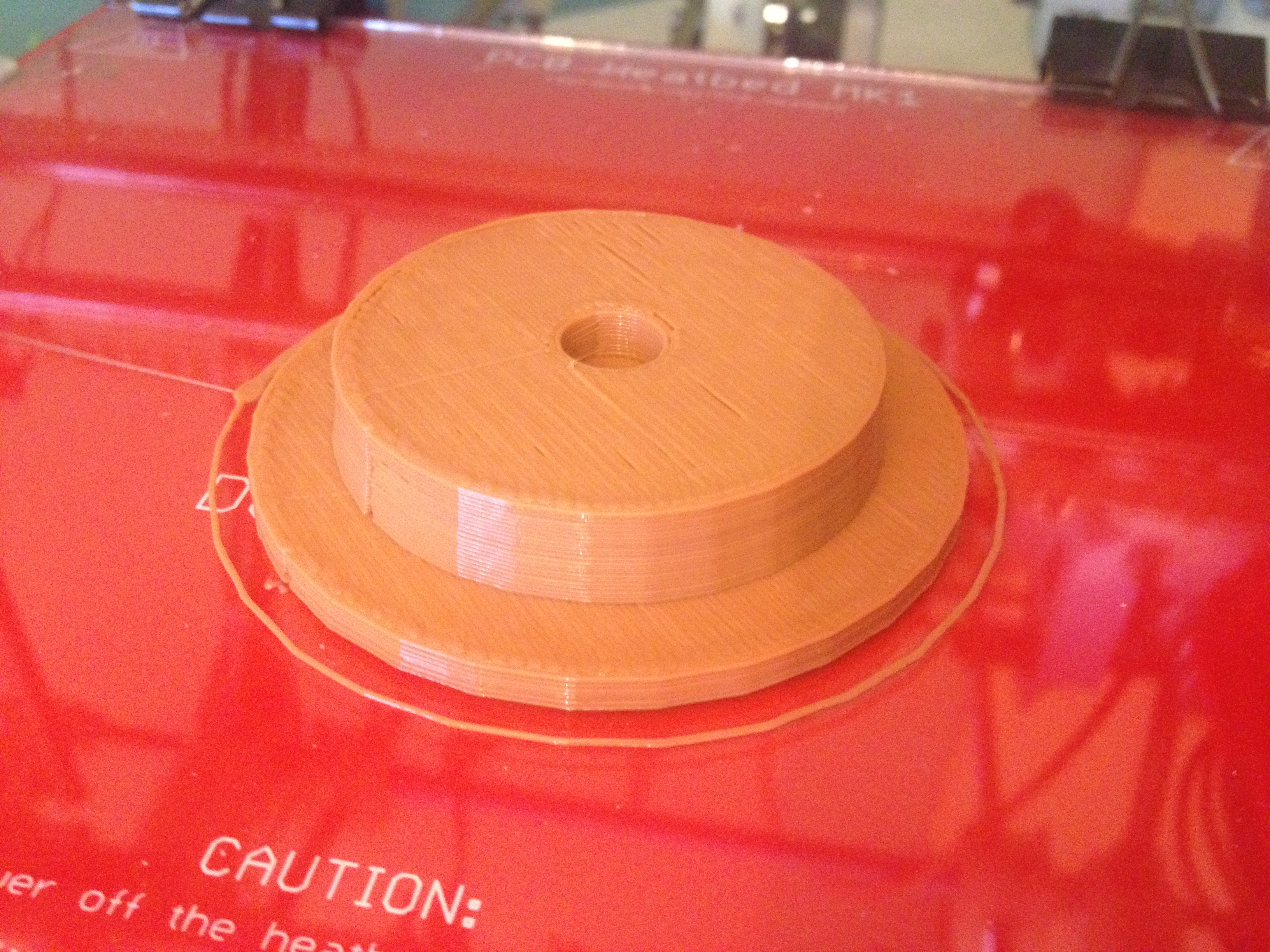
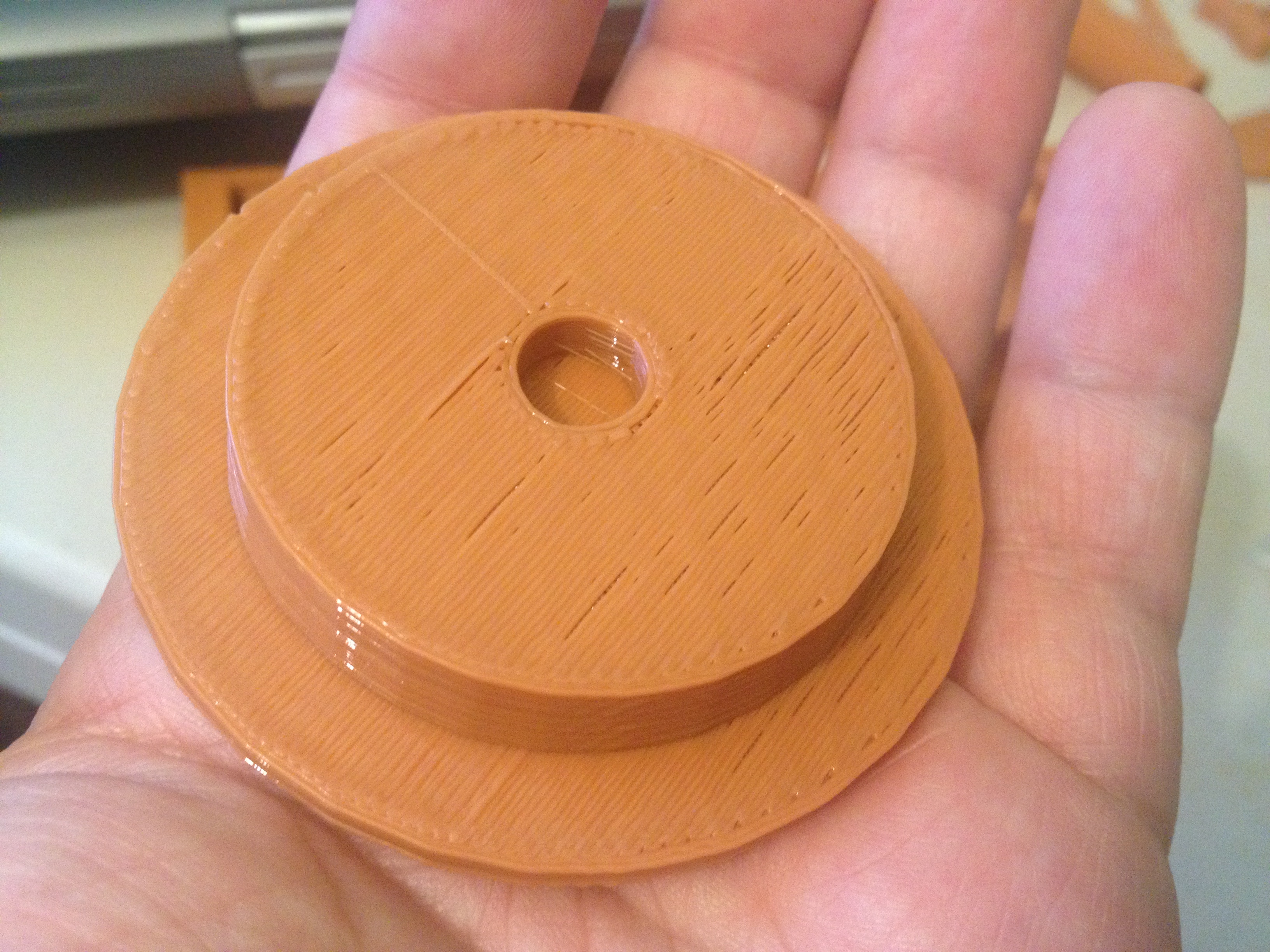
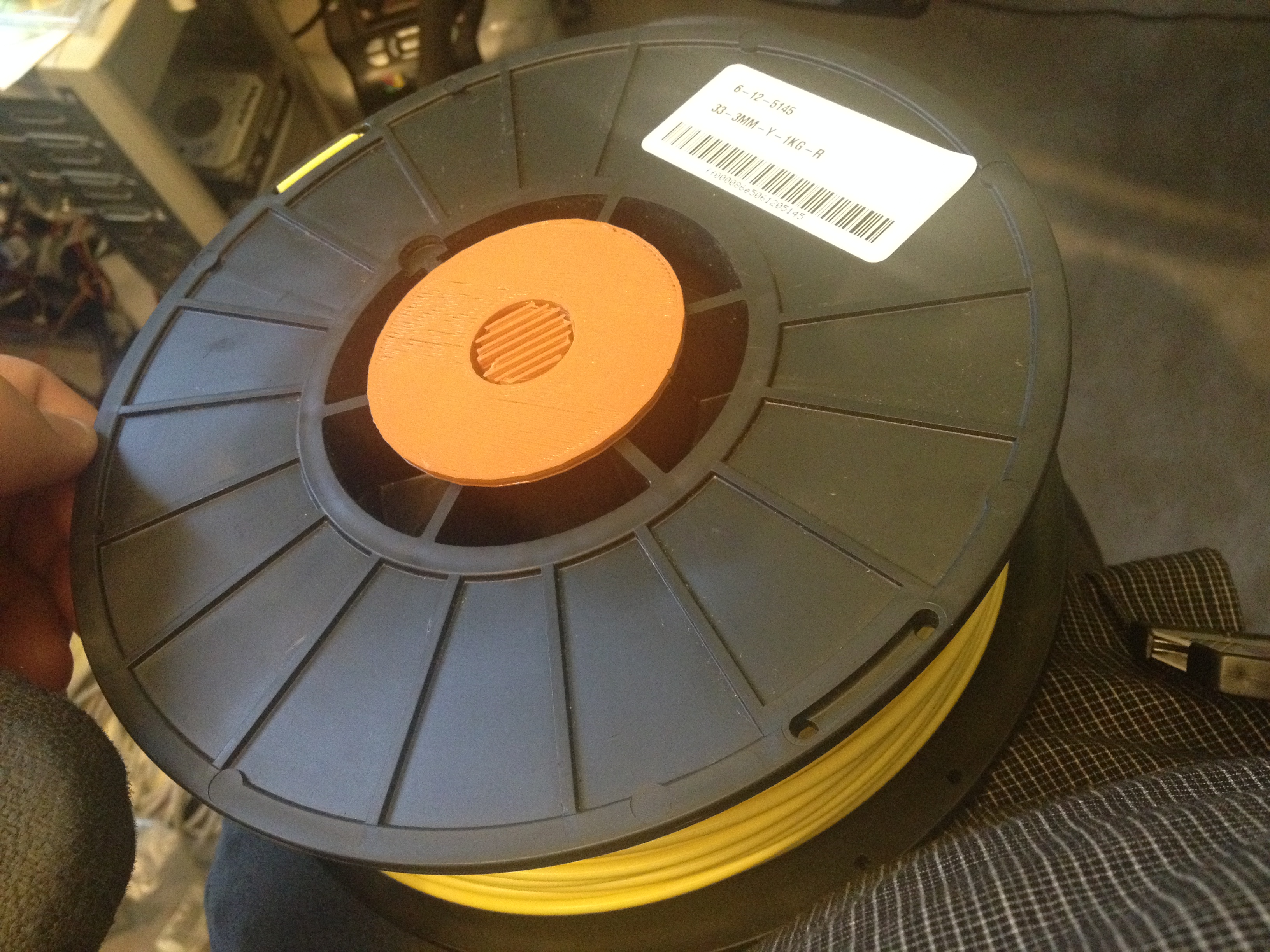
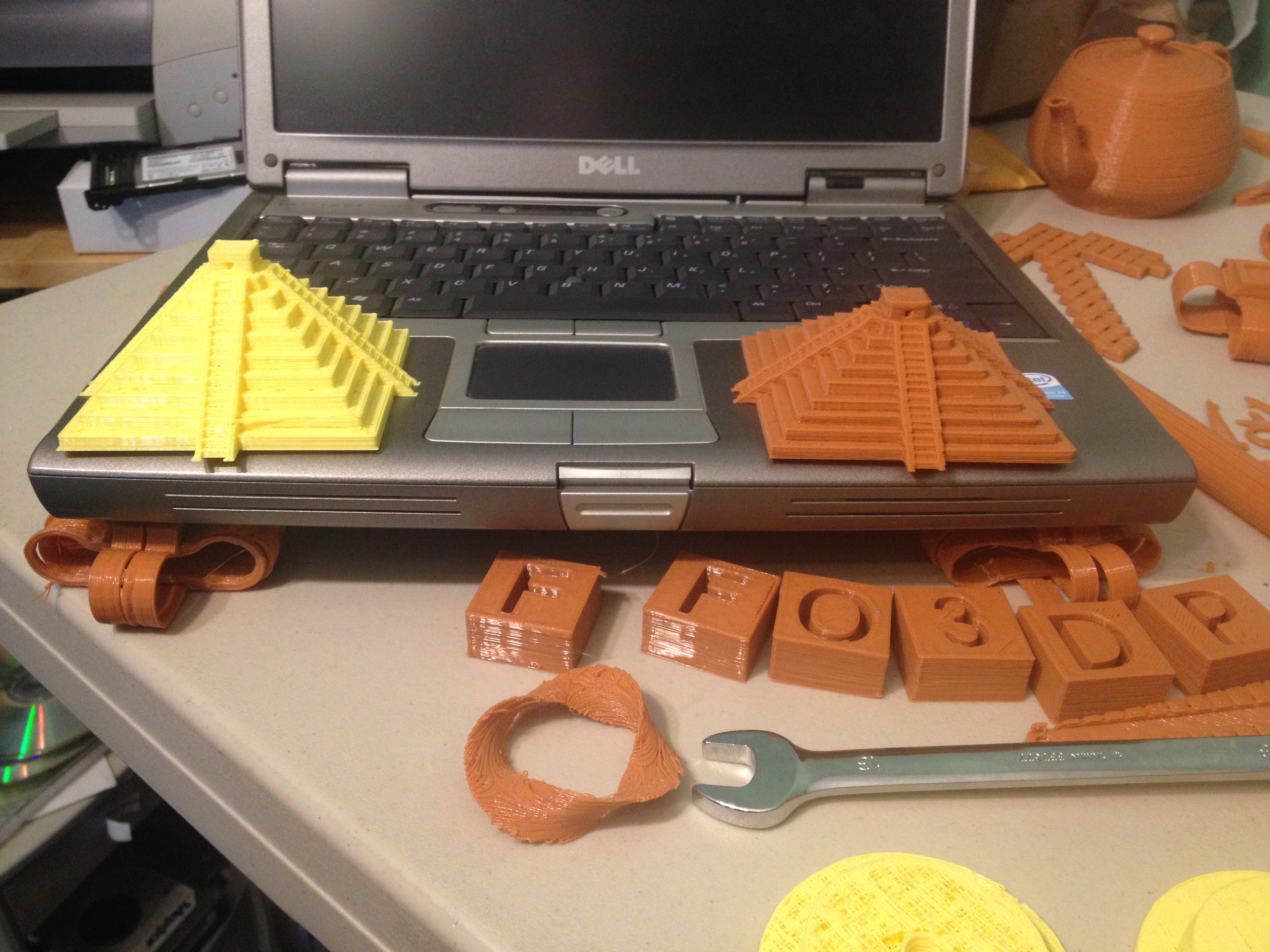
It was right around now that I ran out of that orange/tan plastic. I had a roll of opaque yellow PLA from ultimachine.com, but needed an appropriate spool holder for the type of spool that it was on. Time for another print!
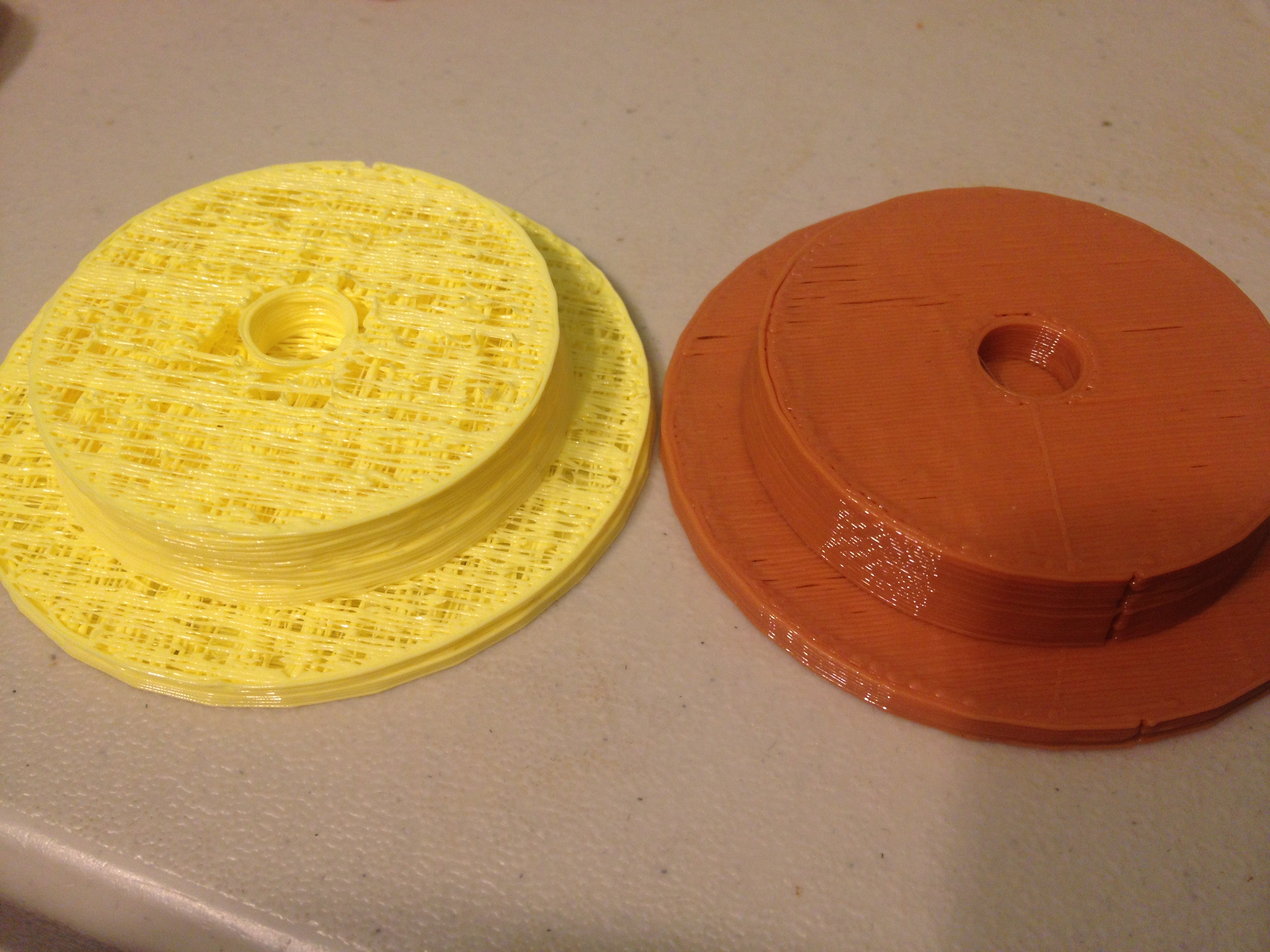
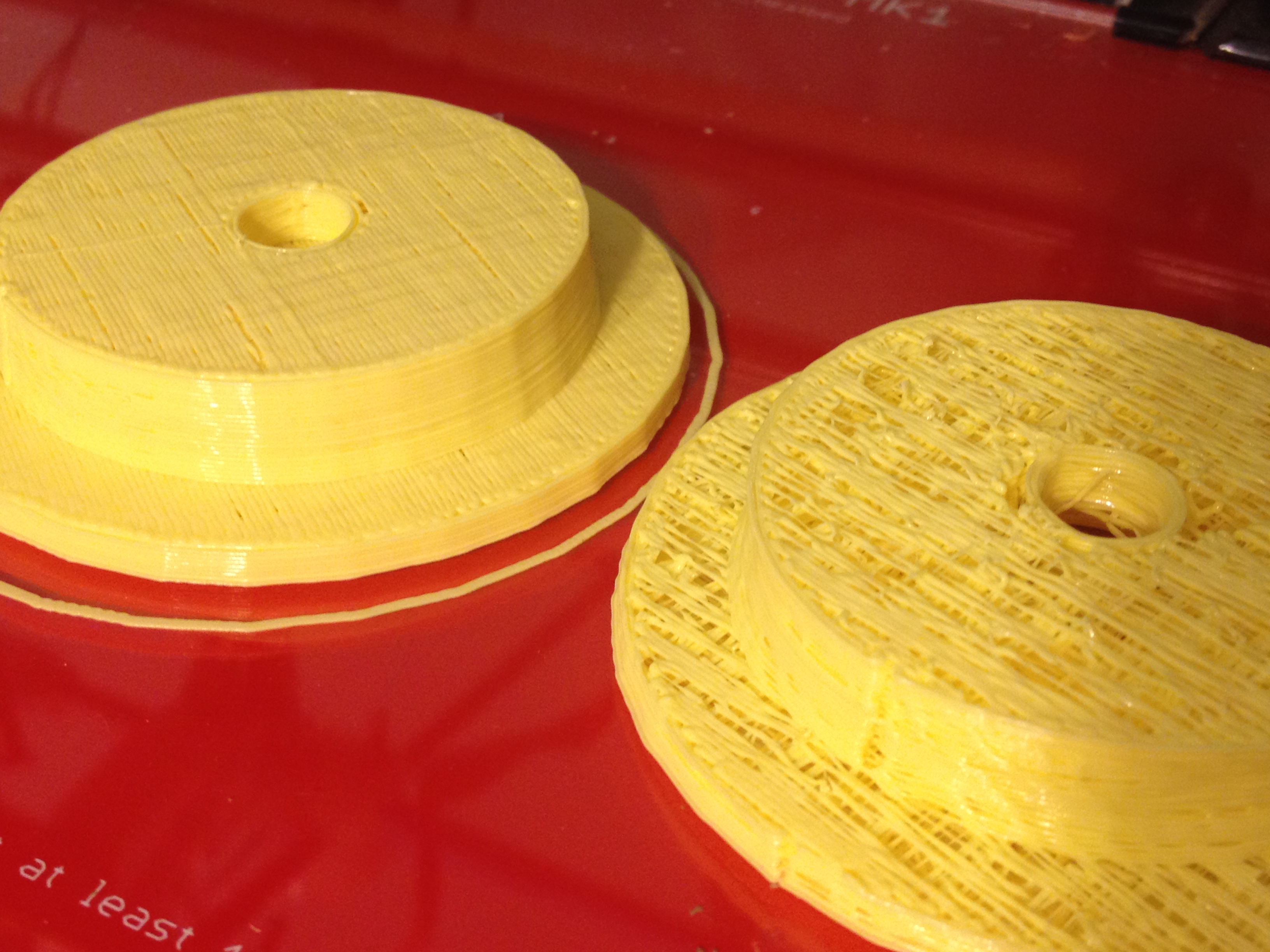
Then when I went to print another with yellow, it turned out awful:
Thankfully I’d just forgotten to adjust the temperature for the new filament (new color = new temperature).
Here is the new print side-by-side with the awful print:
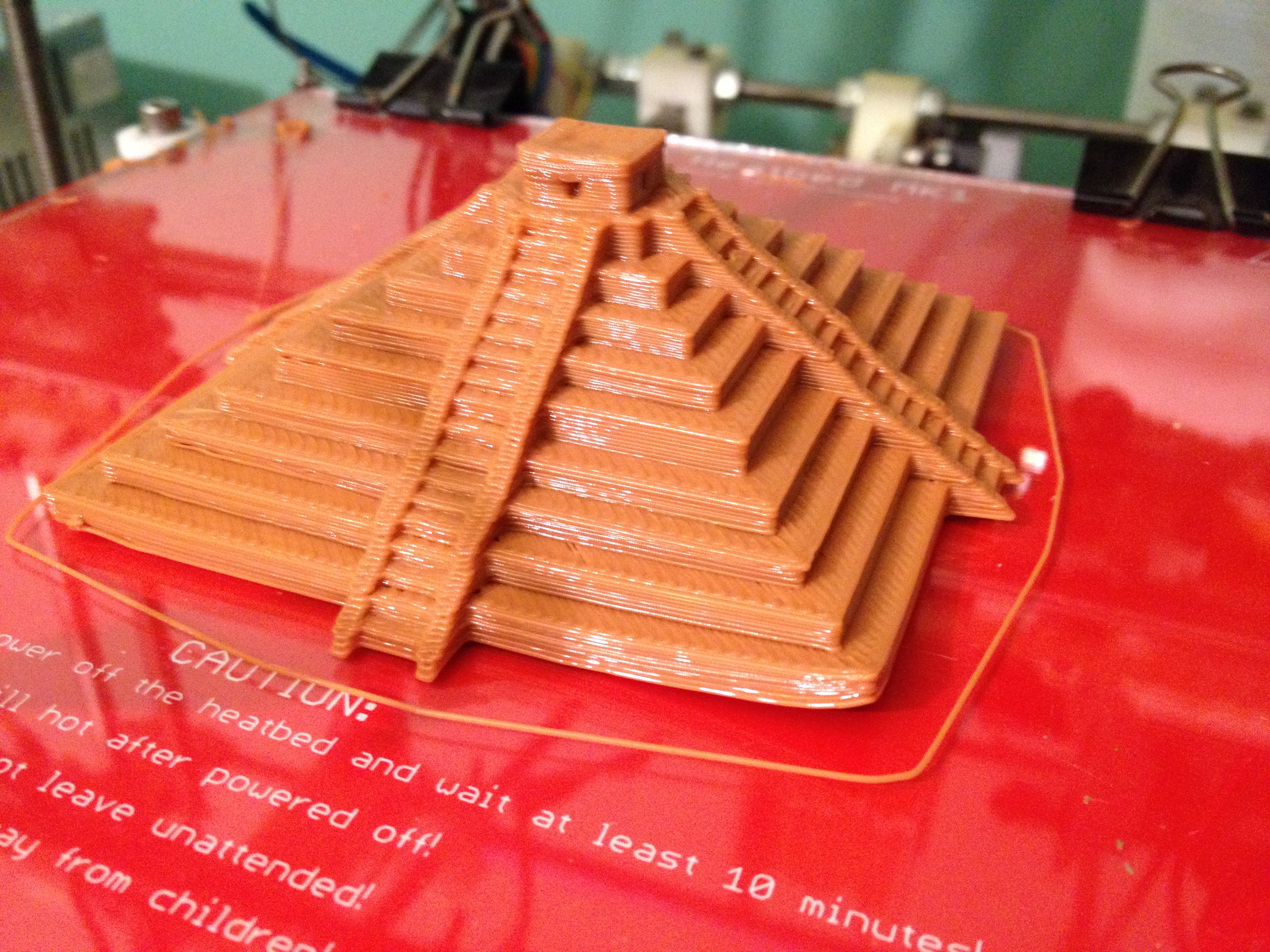
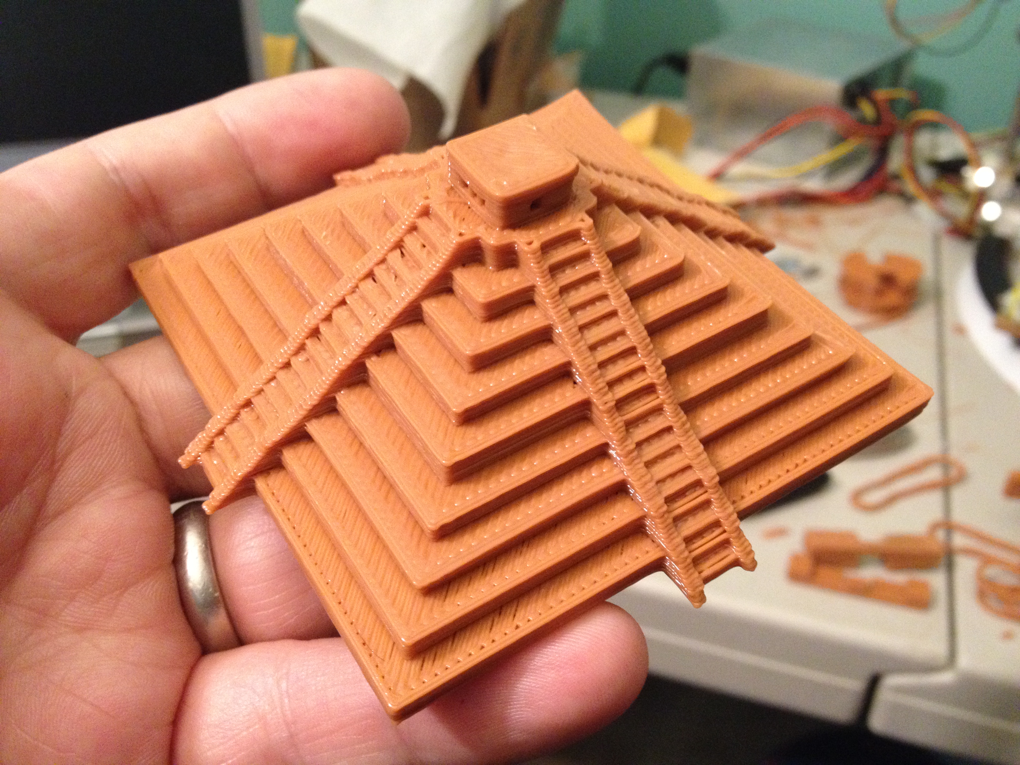
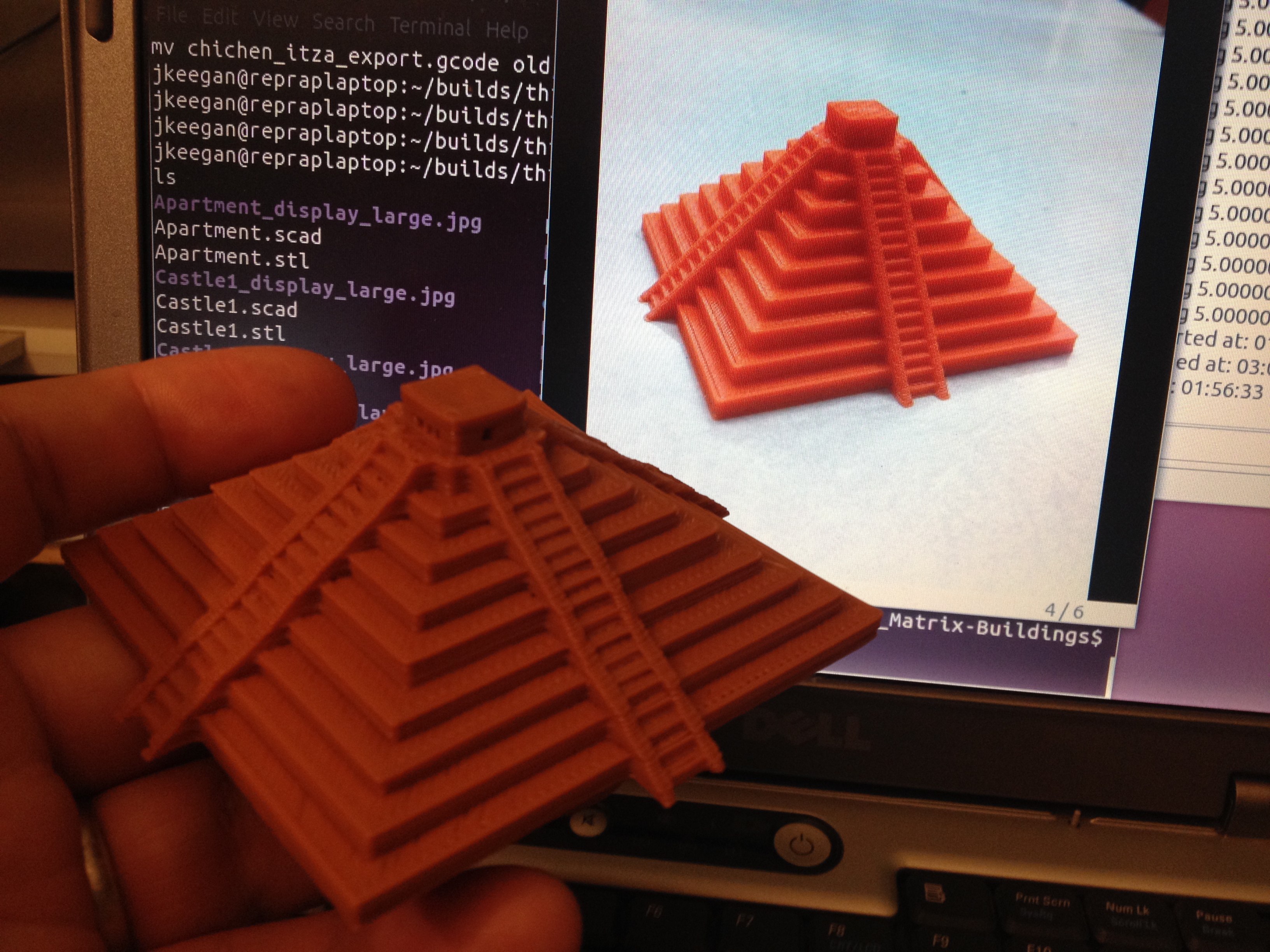
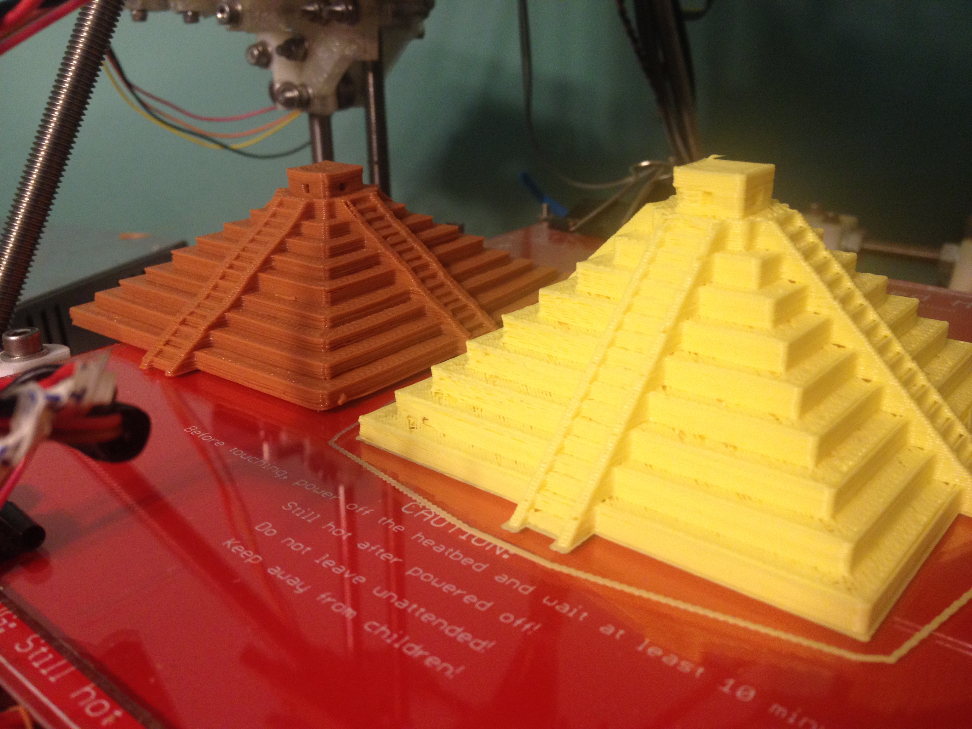
Having my official print for the day done, I tried redo-ing the Chichen Itza print, which had previously suffered from bad Z height, at least partially because of a lack of lubrication.
Here it is against the original for comparison. Note the increased/accurate height on the new yellow print, and the consistency of the stair height.
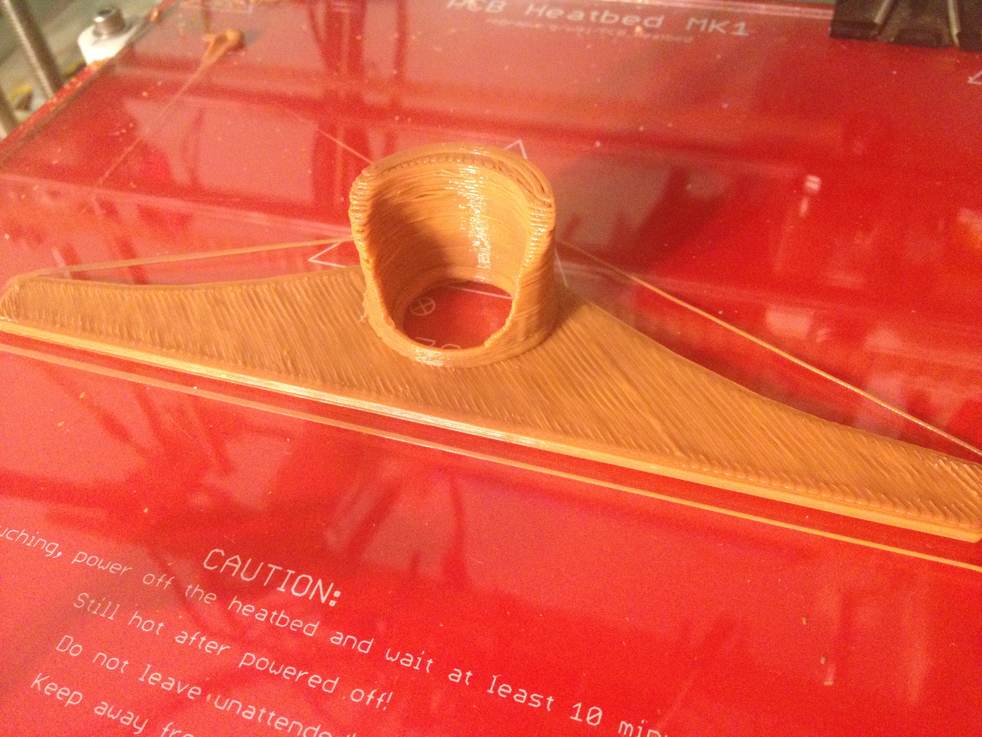
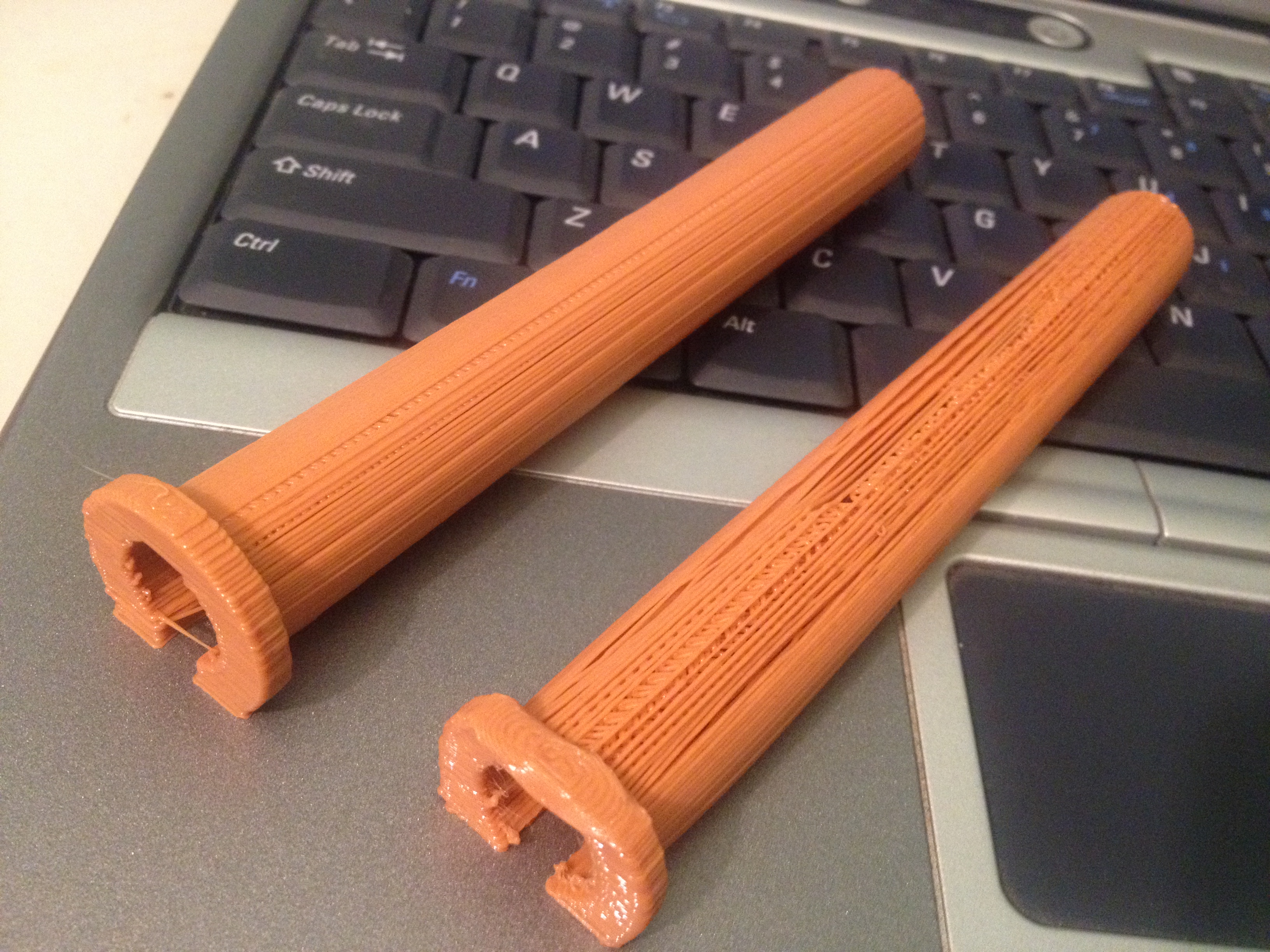
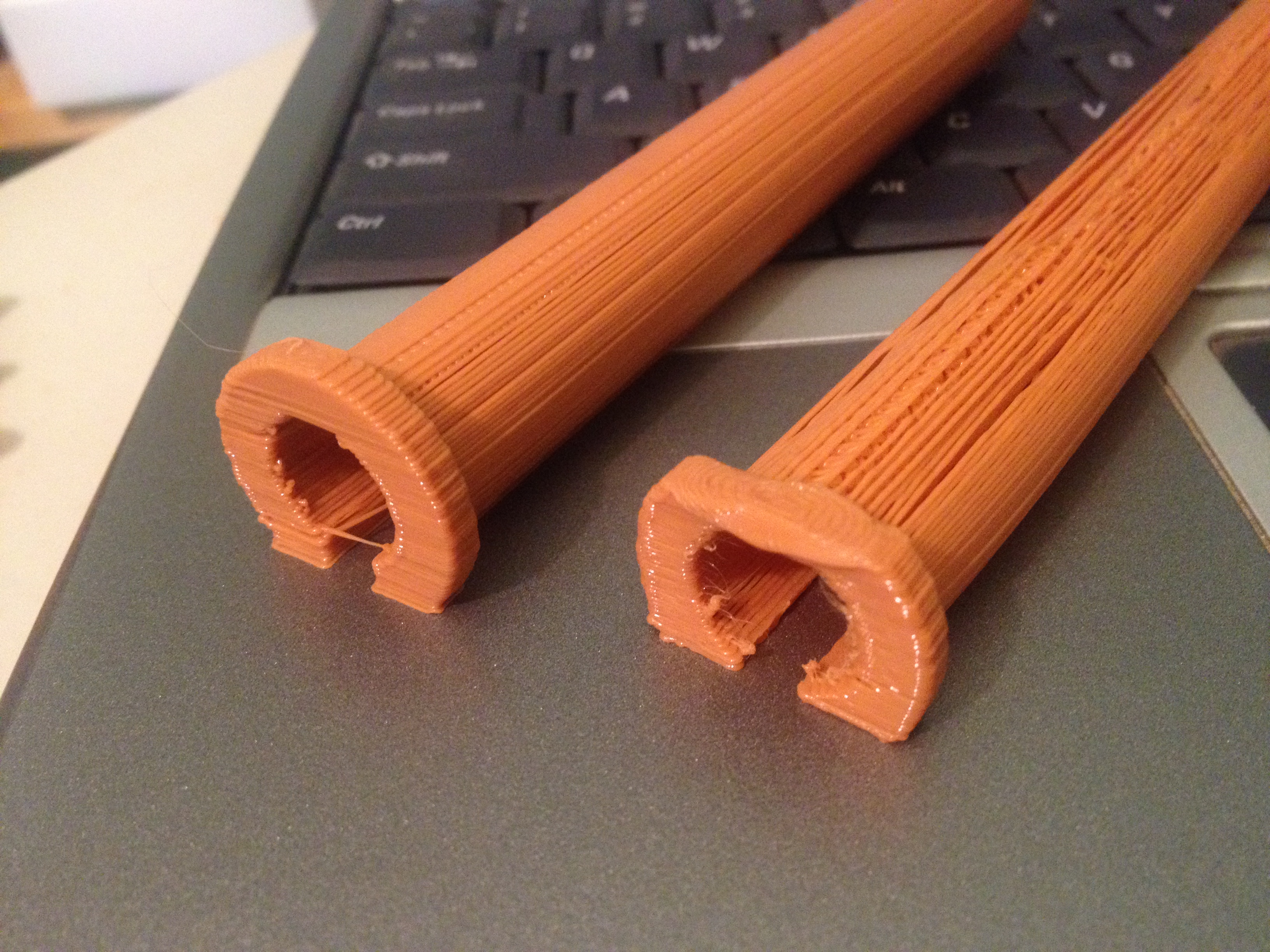
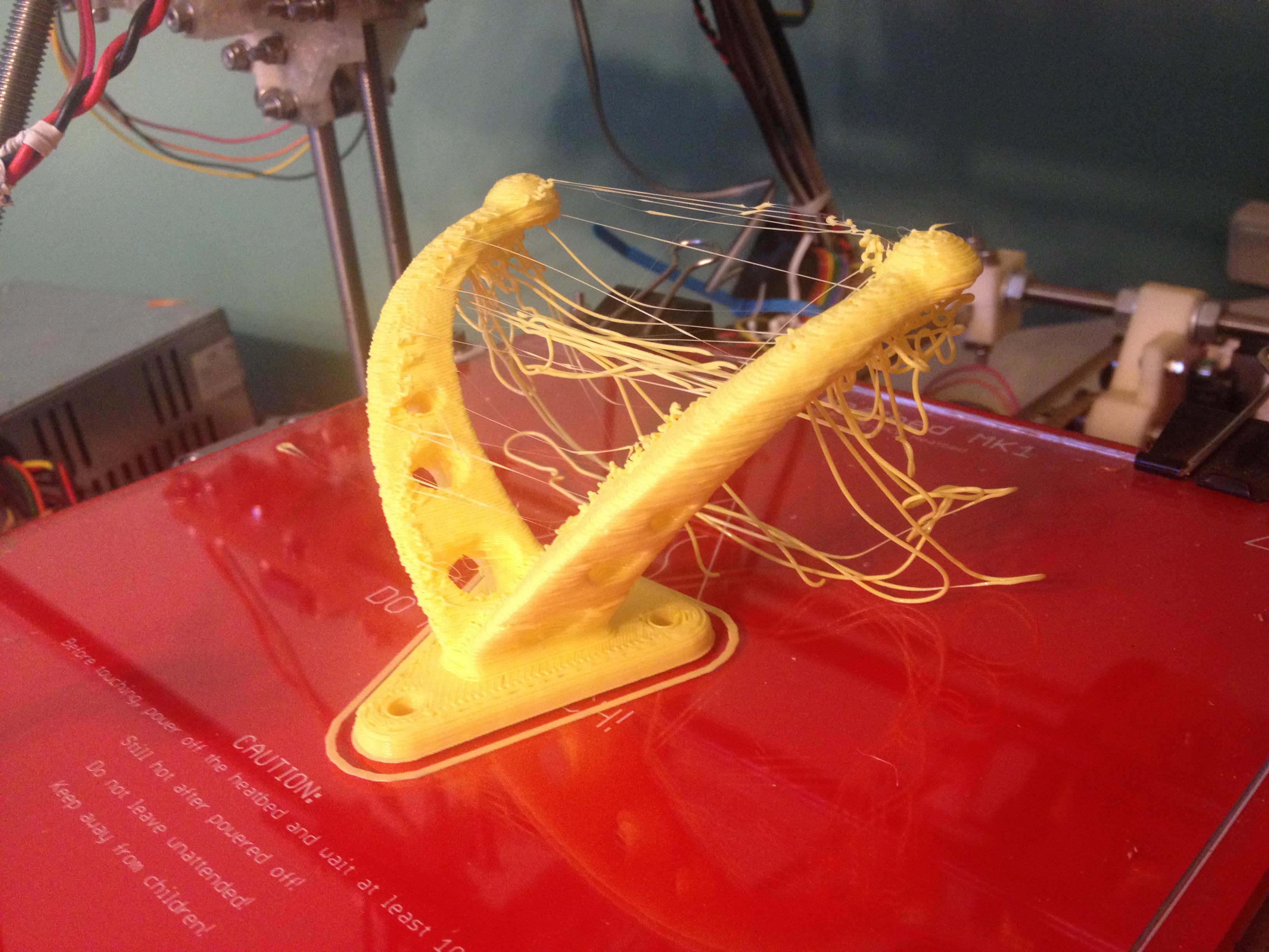
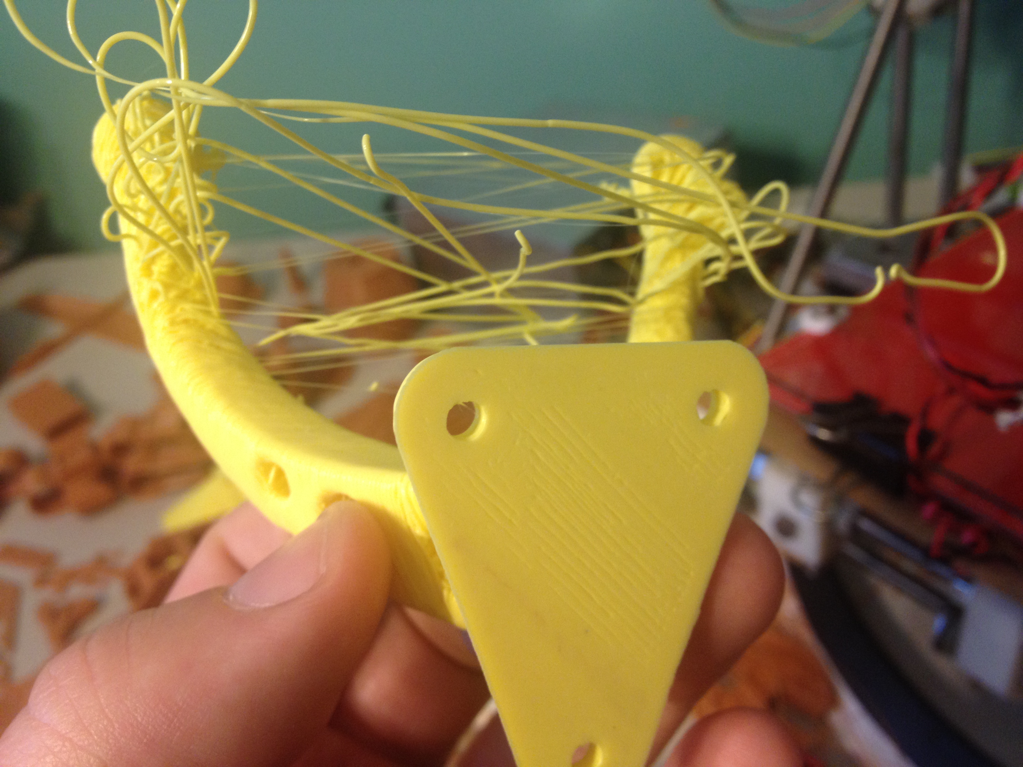
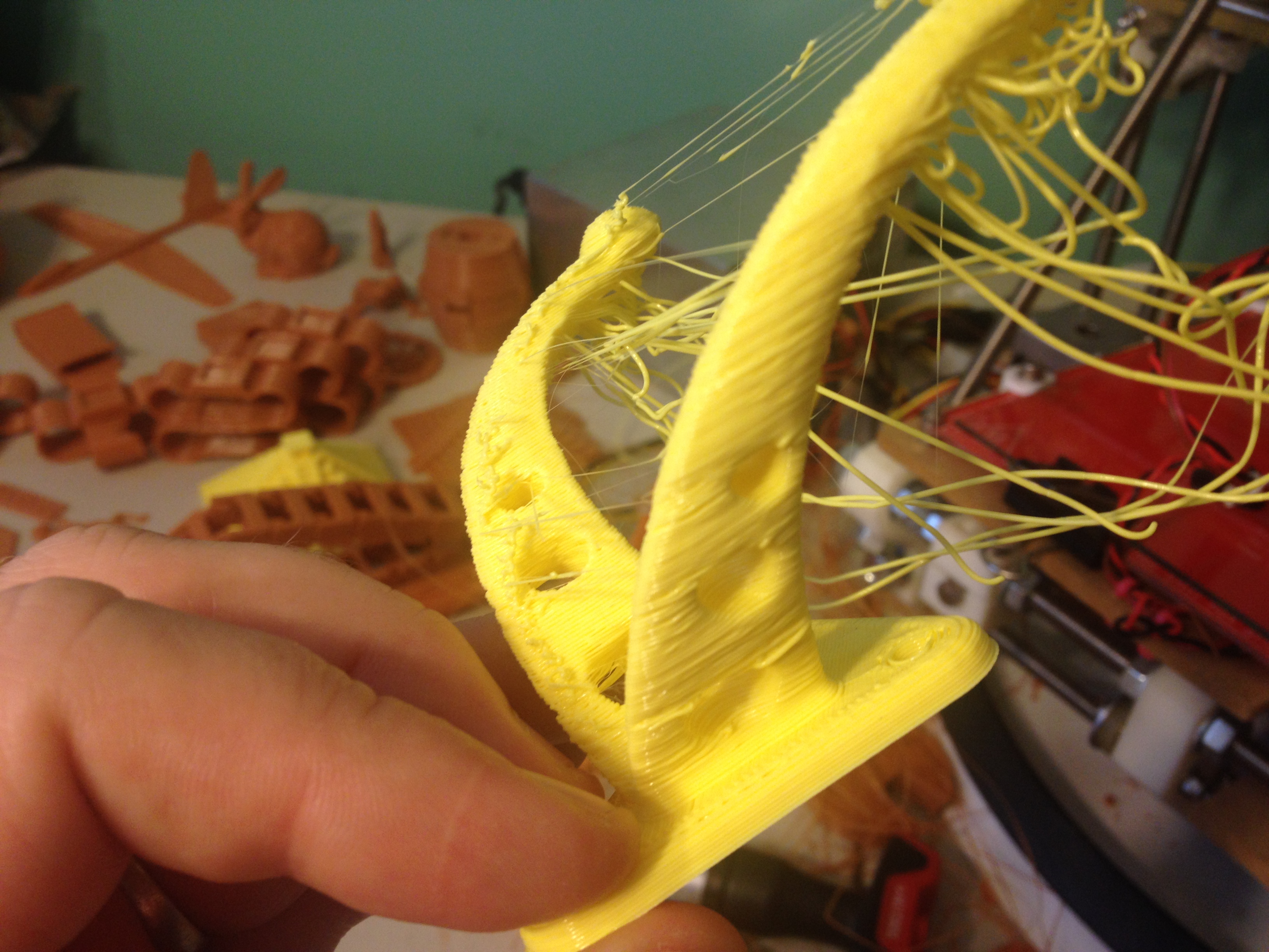
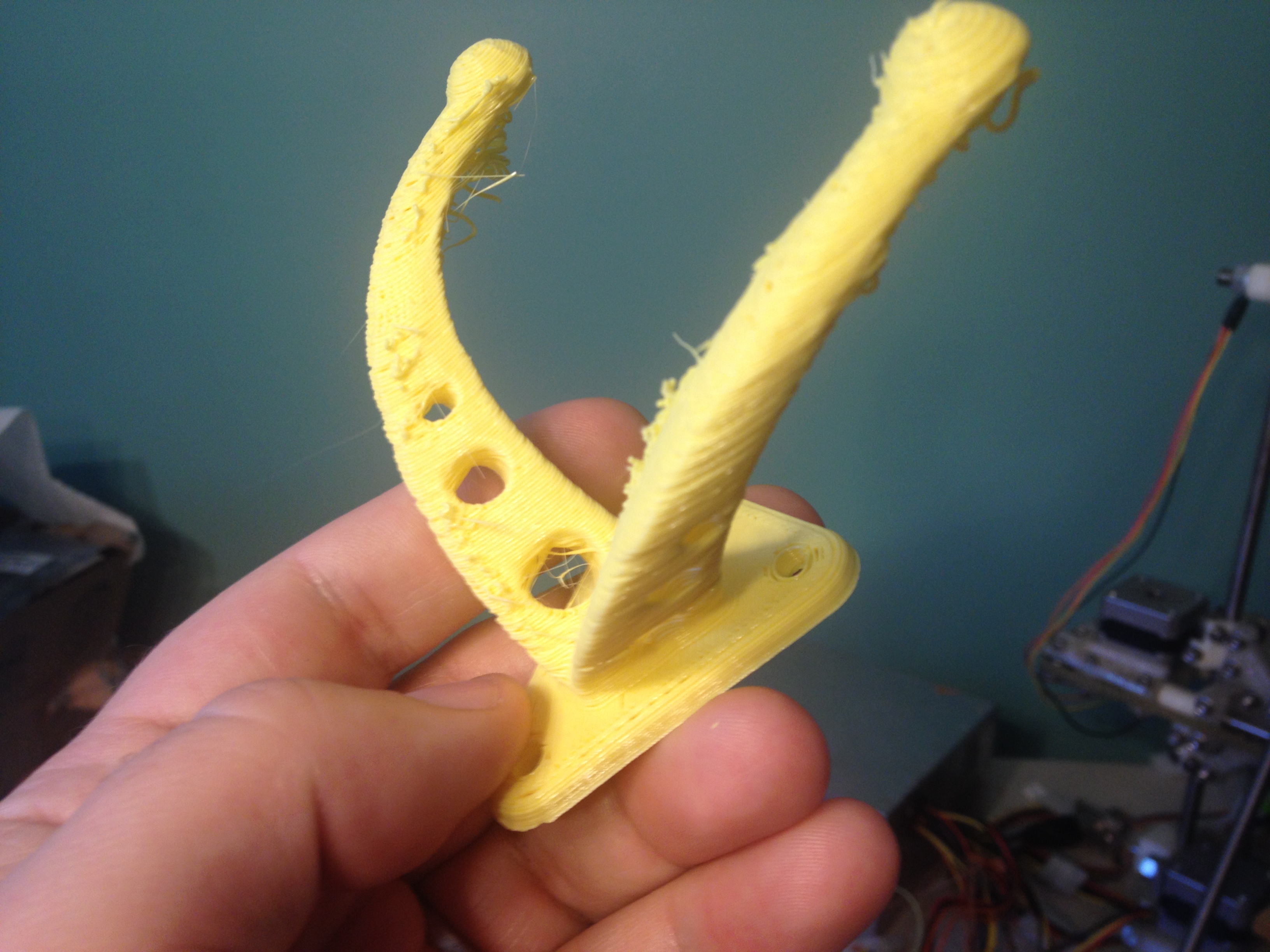
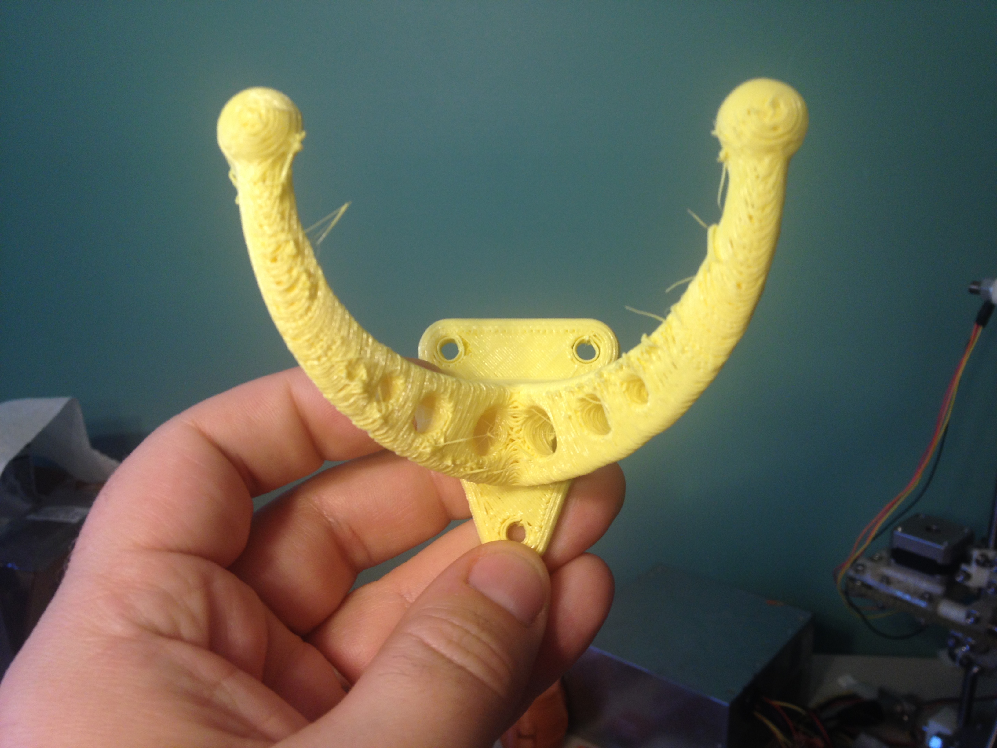
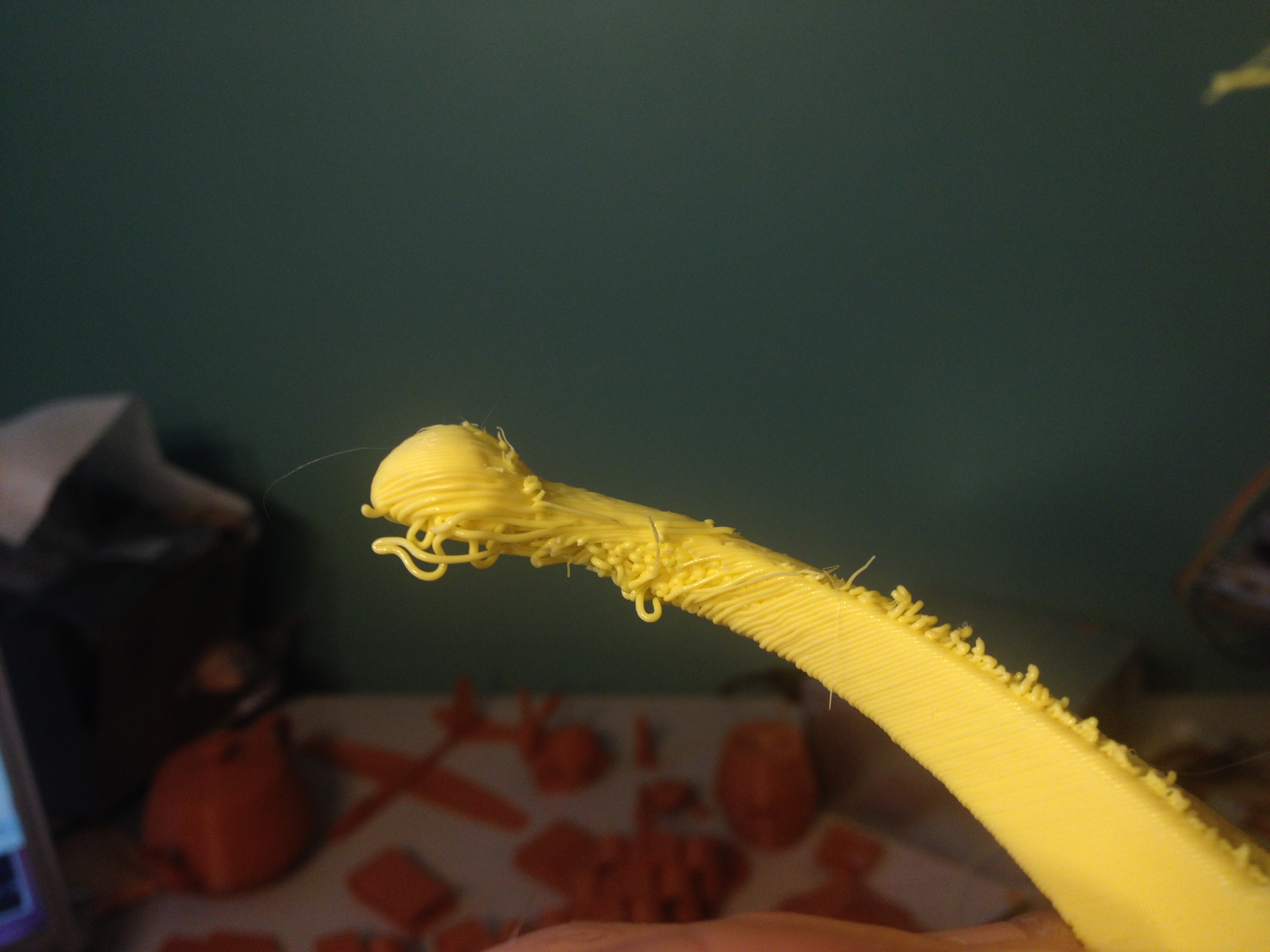
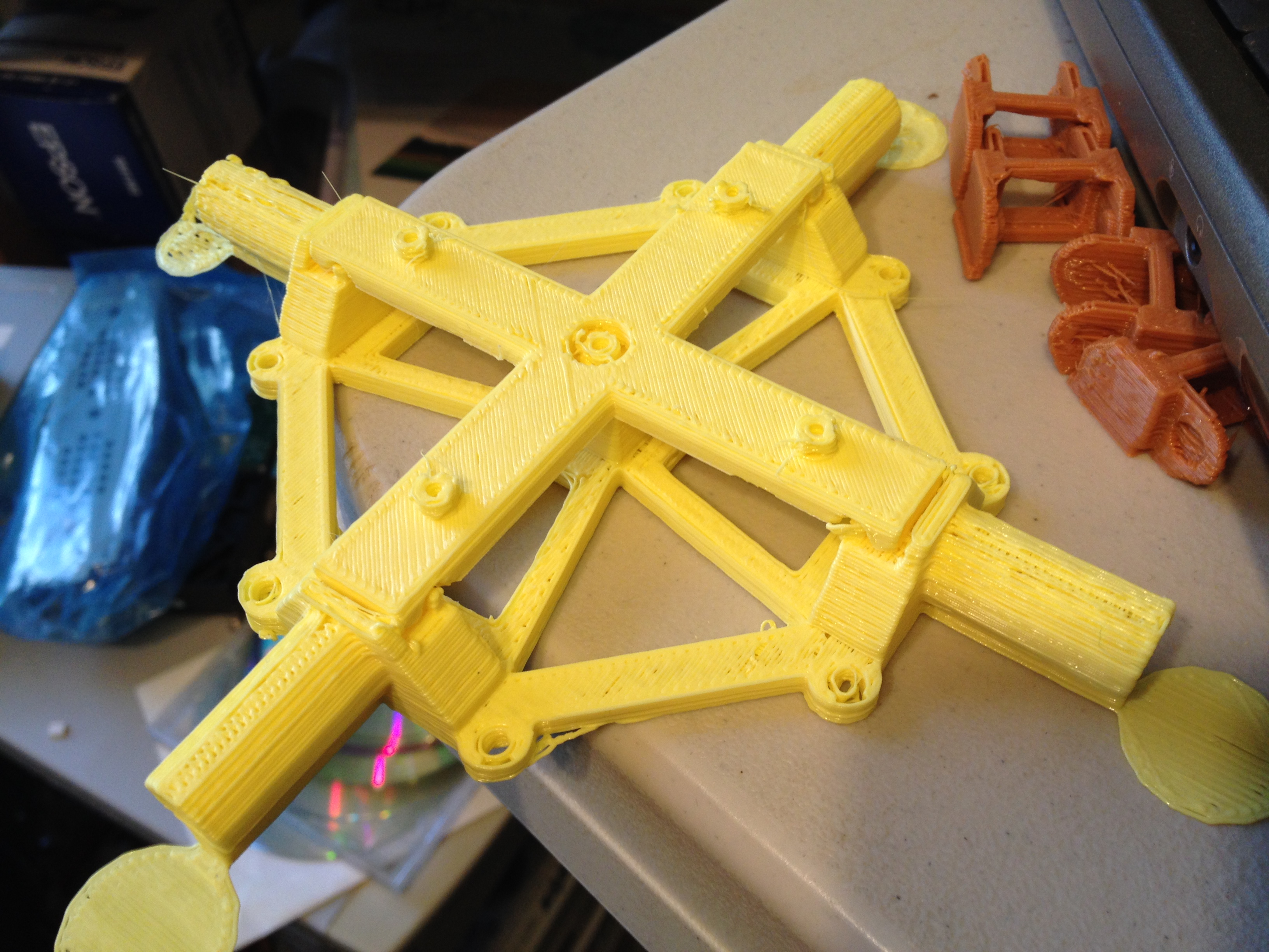
Coat Hanger – Dual Prong, center parts 1 and 2 of quadcopter – February 21, 2014
Next I wanted a hook for my towel in the bathroom (full disclosure – one year later, not only did I not mount/use this hook, but I bought Laurie another hook from a store that uses a special adhesive to stick to the wall incredibly well).
As you can see in that last picture, the ends of the hook didn’t come out that great, so I tried printing it again, this time with support material.
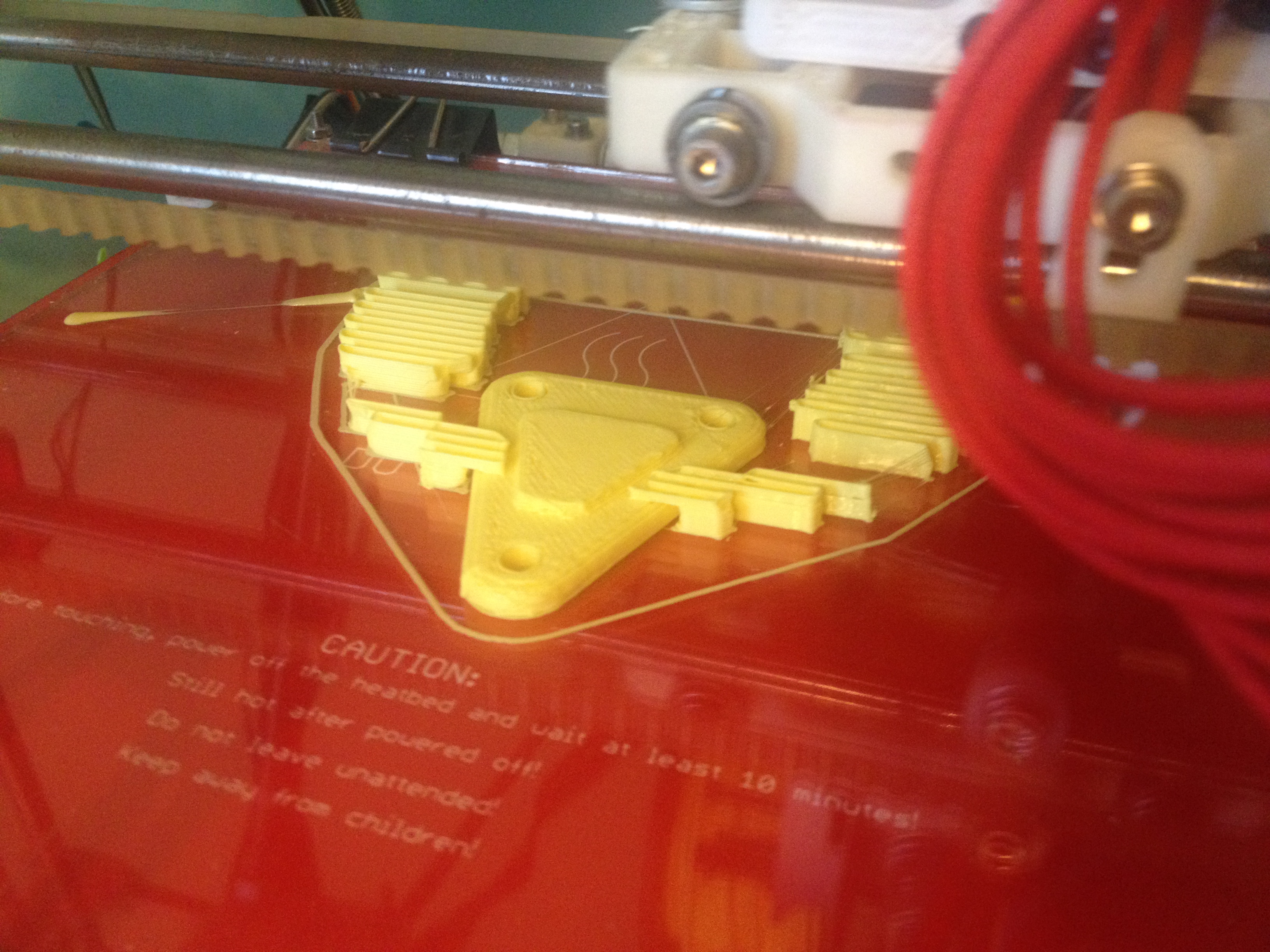
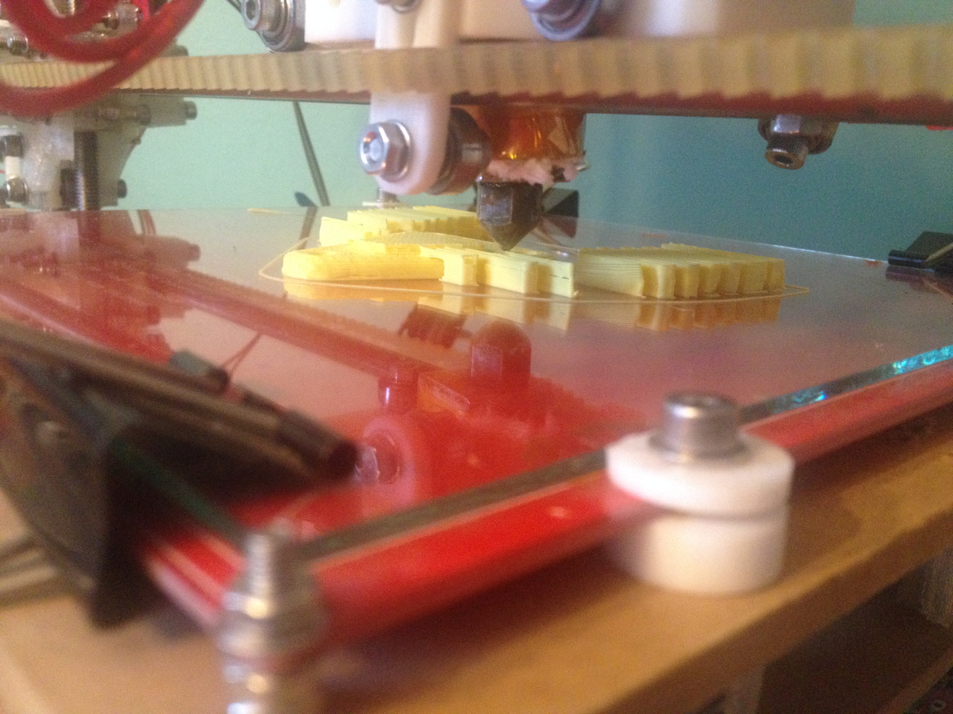
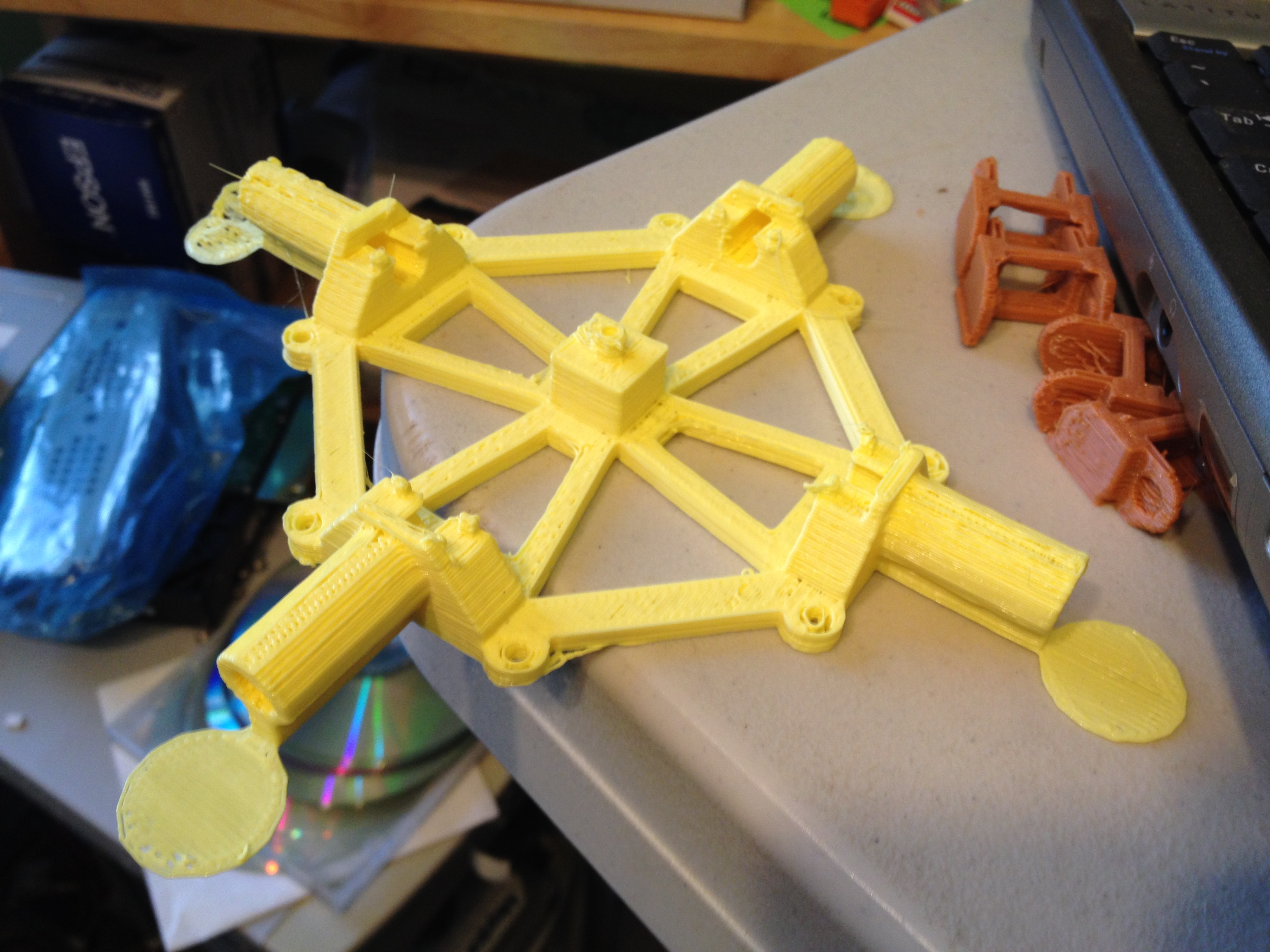
I also printed two parts of my quadcopter that I’d previously printed with clear PLA. If they were stronger I’d use those, and if the same, they’d act as a spare.
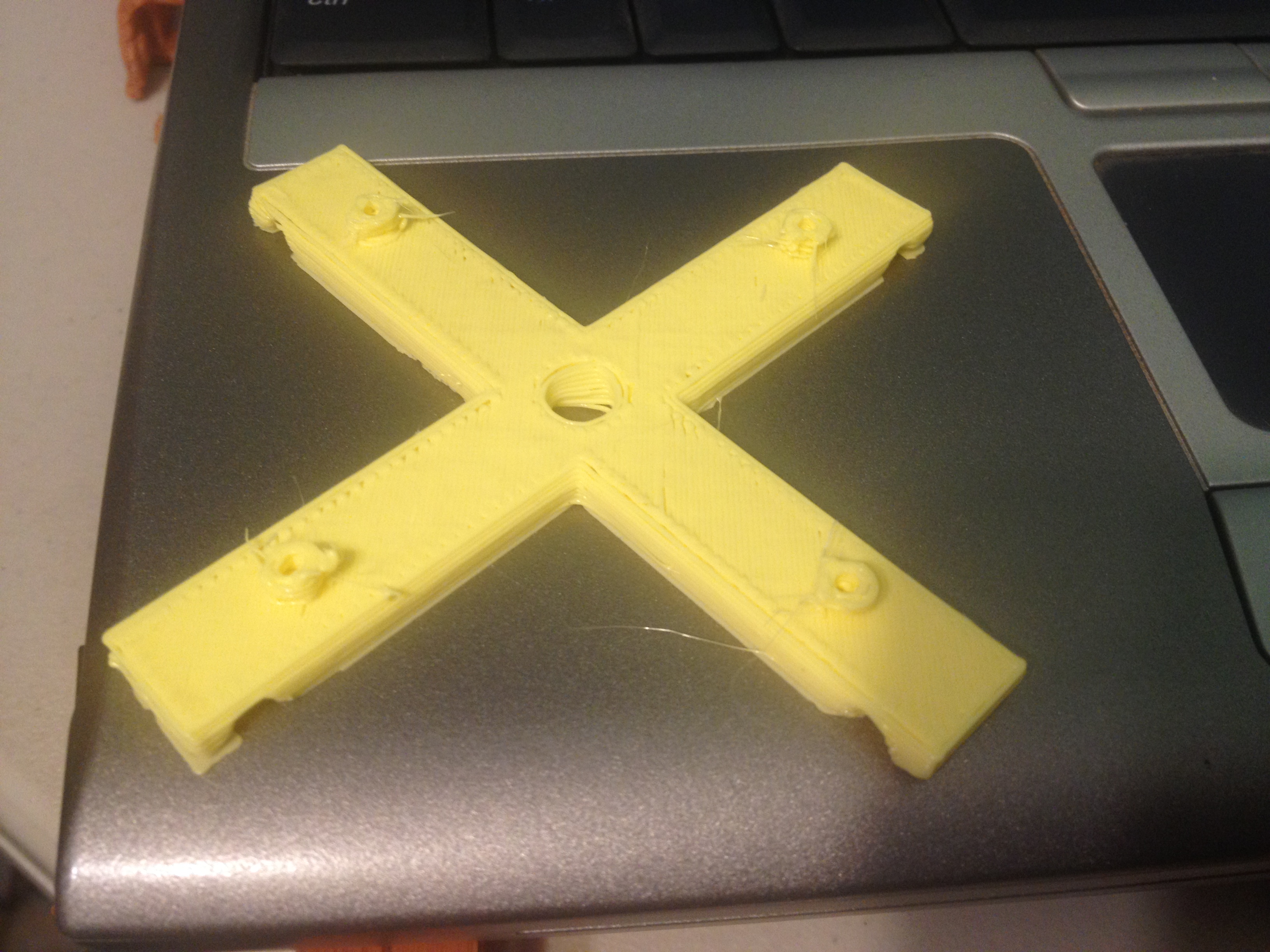
Here’s the mount for the electronics (body part 2):
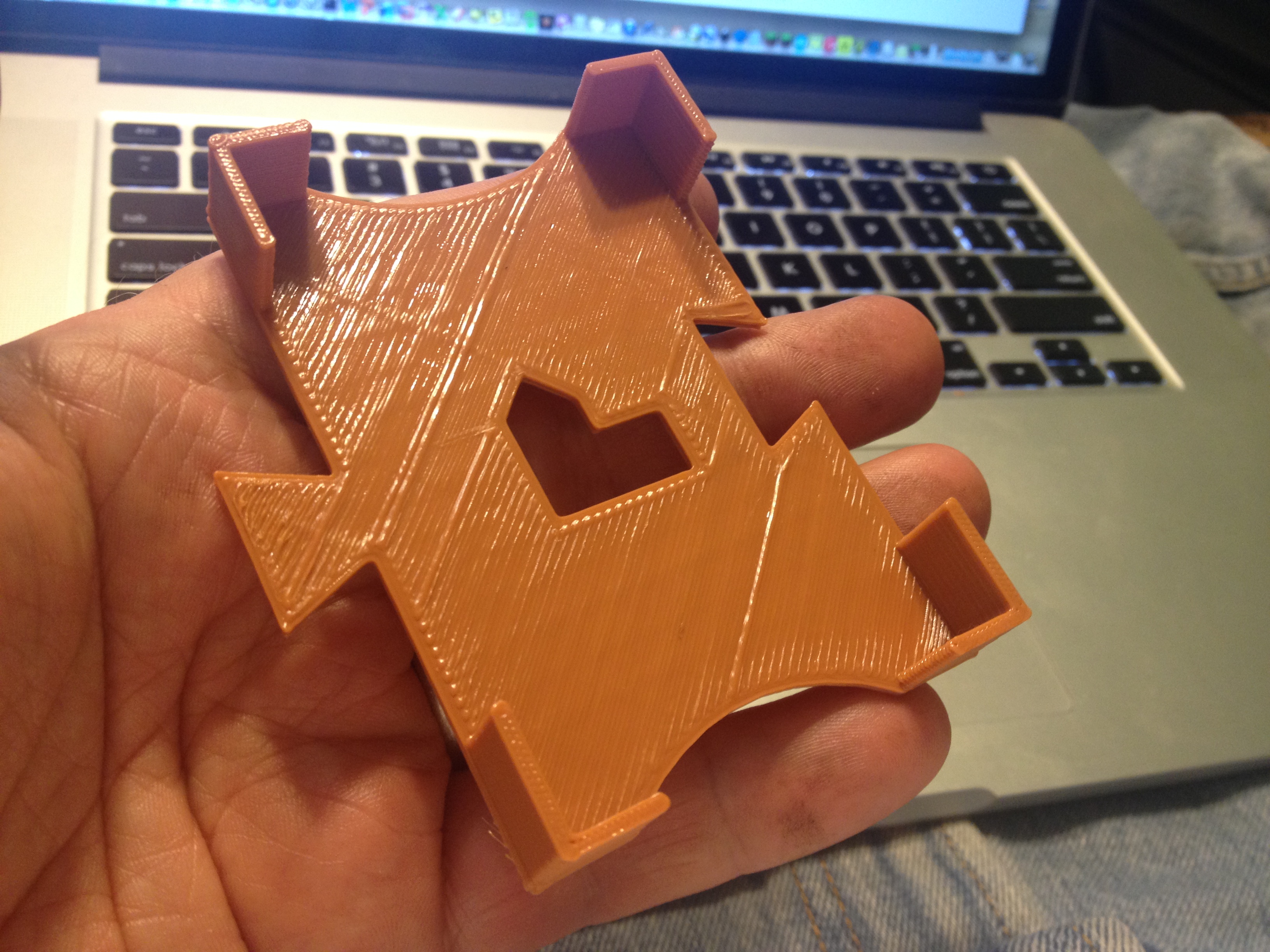
Here was the center base of the quadcopter (body part 1):
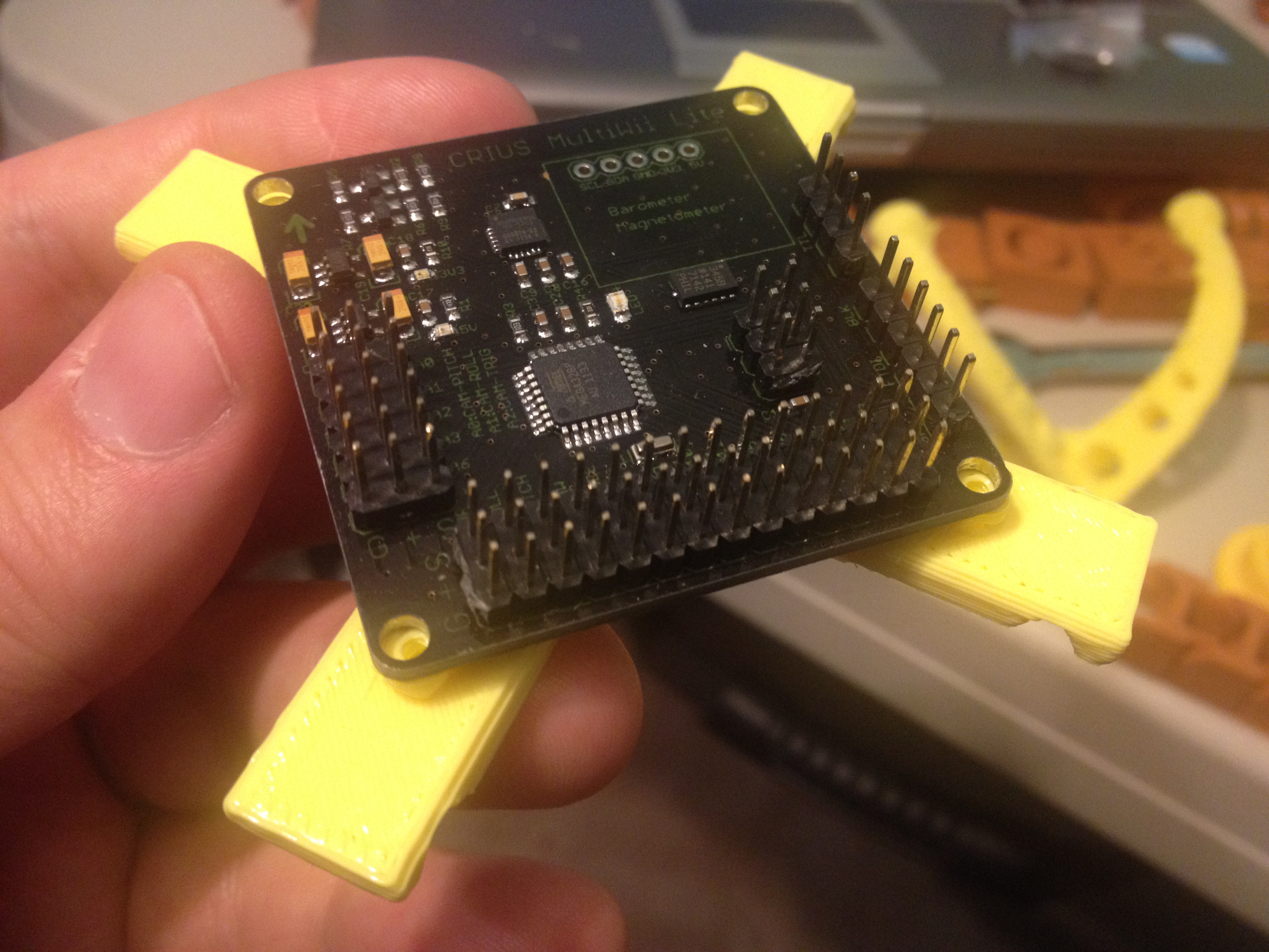
…and here is the electronics mount in place over the center base:
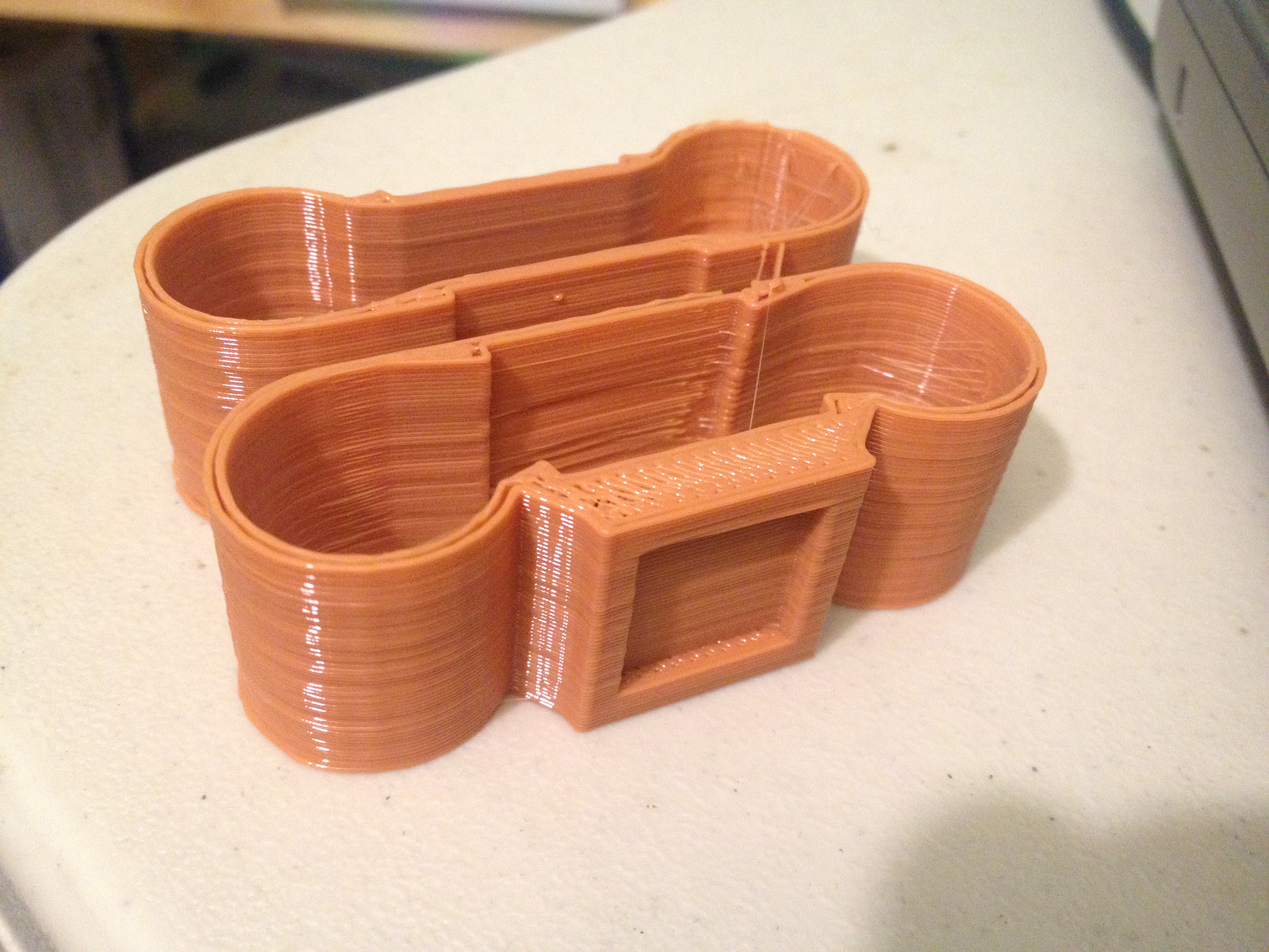
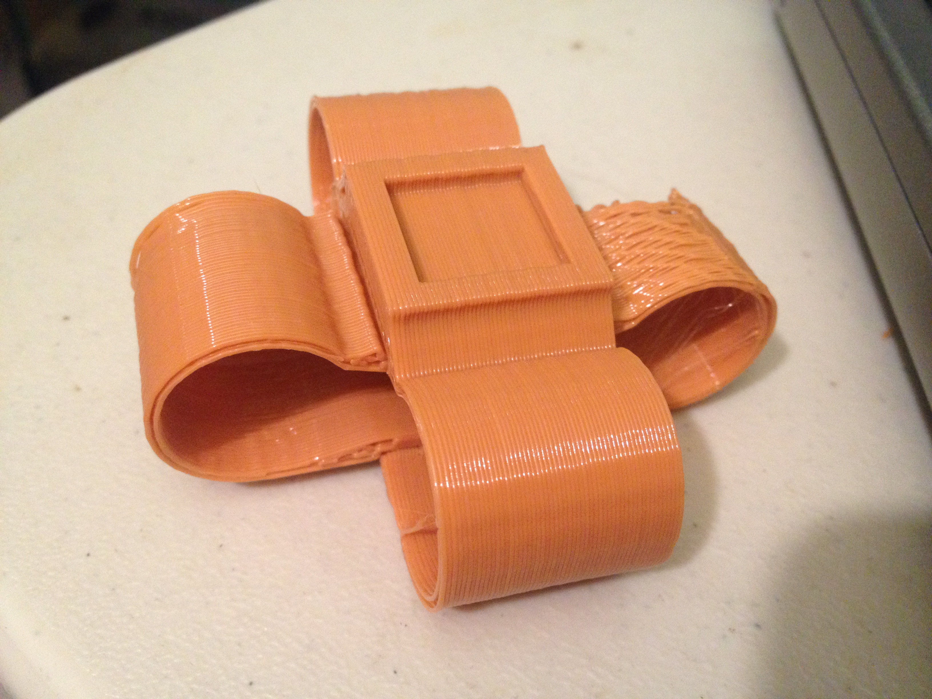
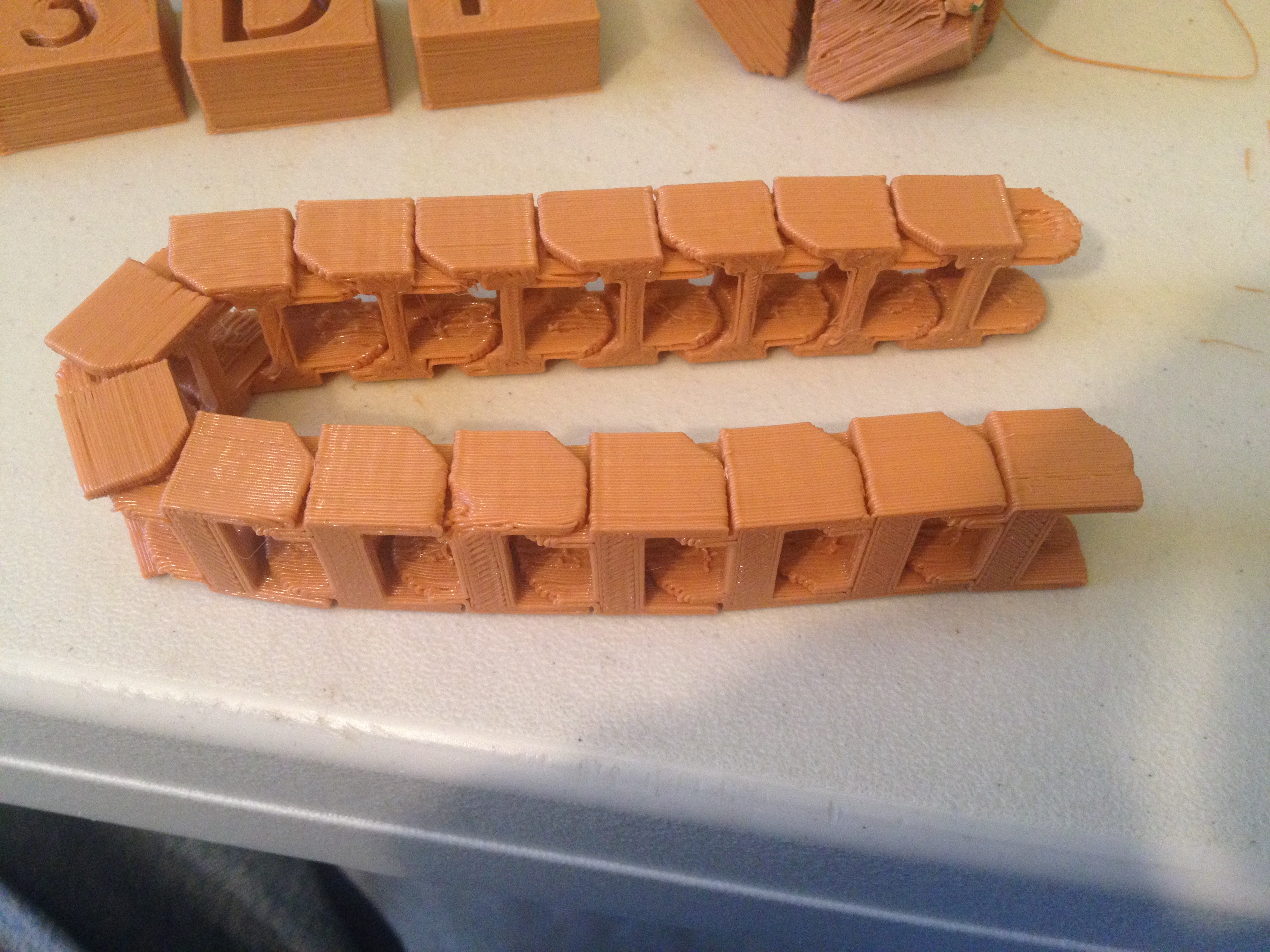
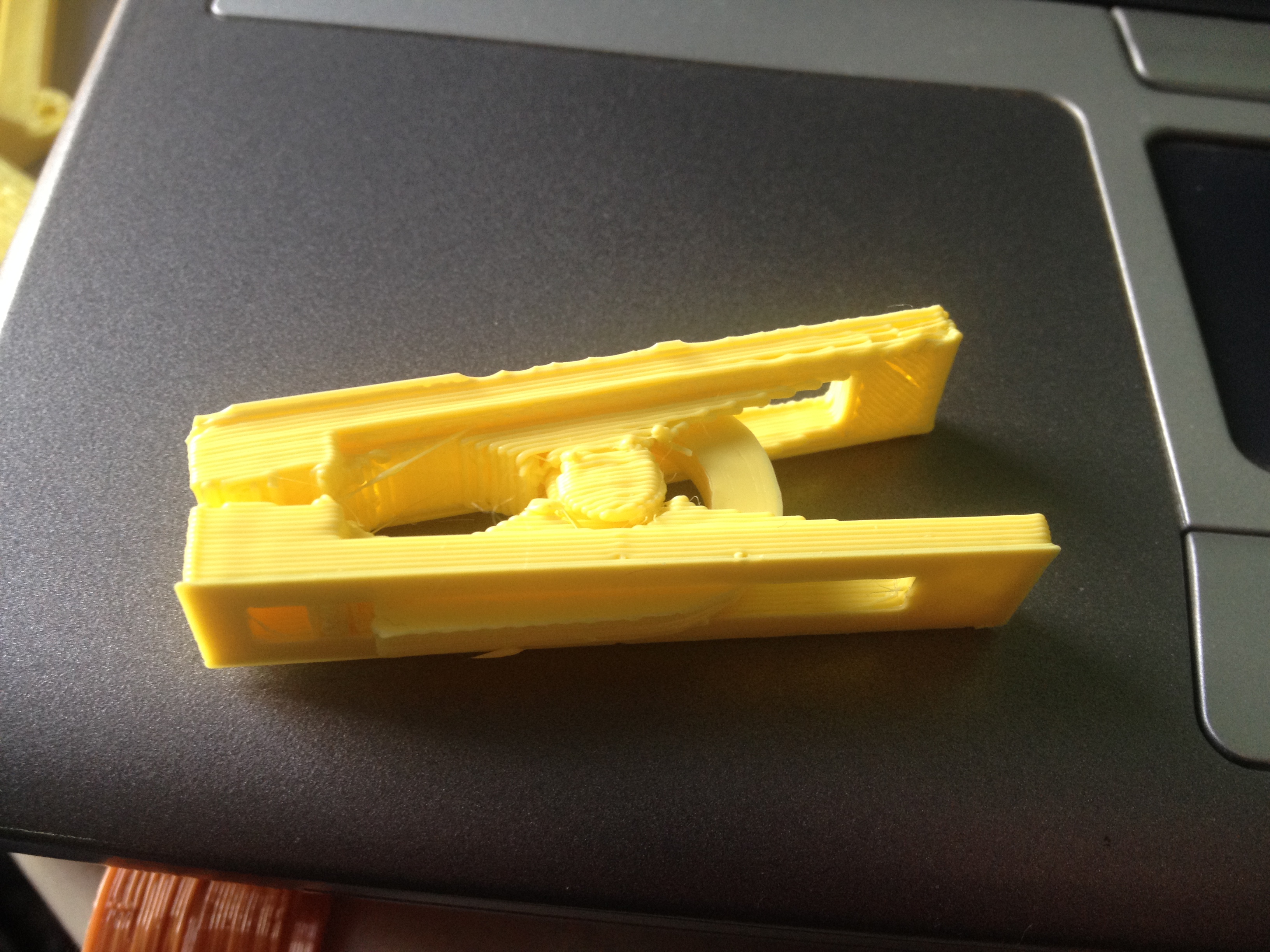
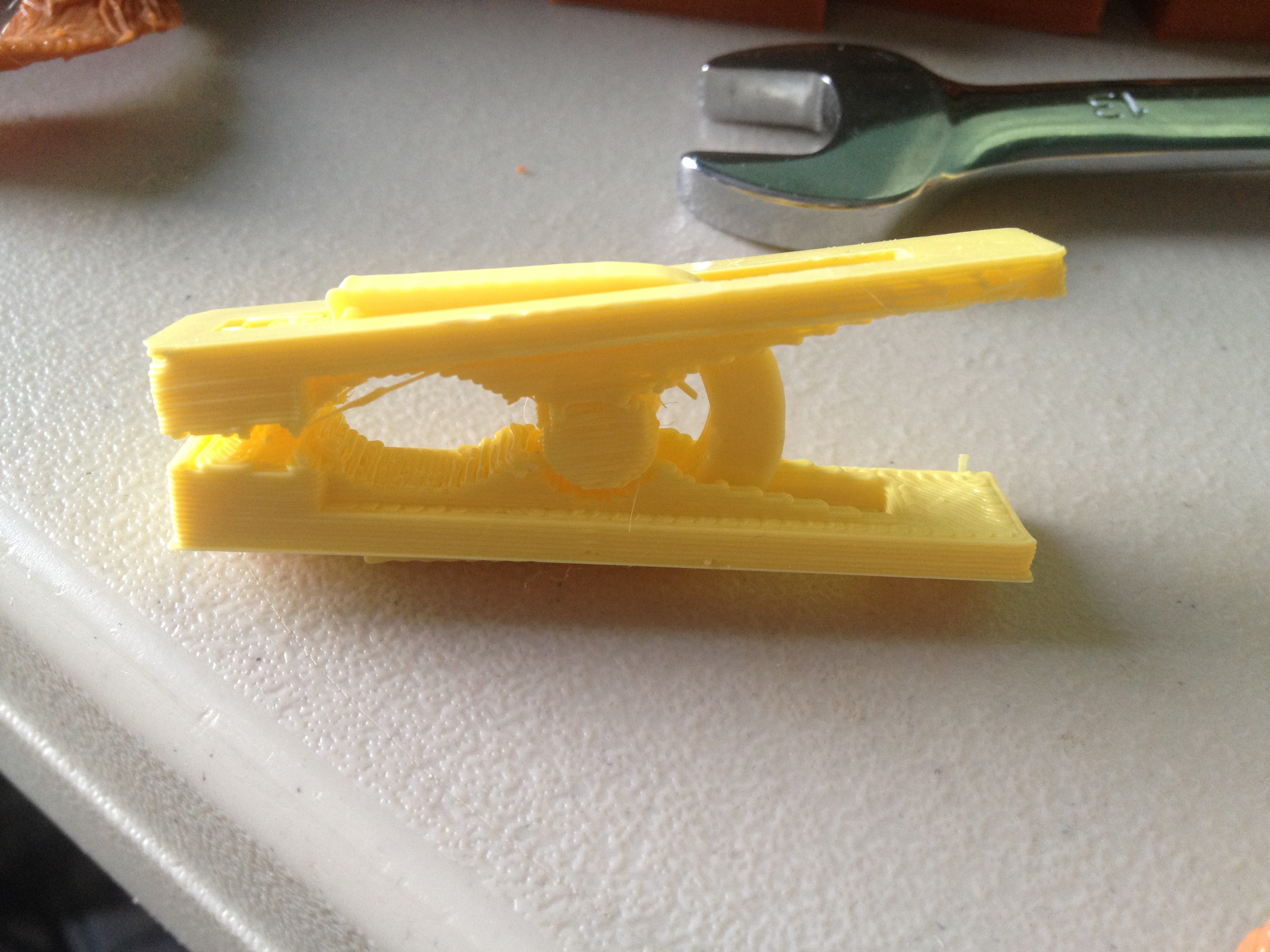
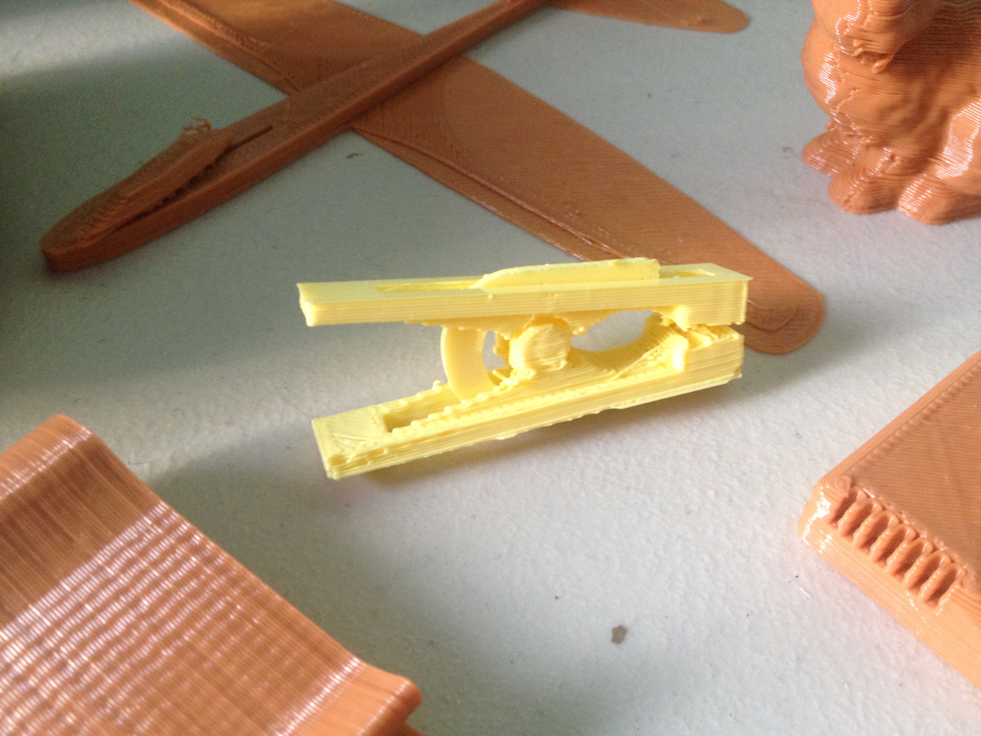
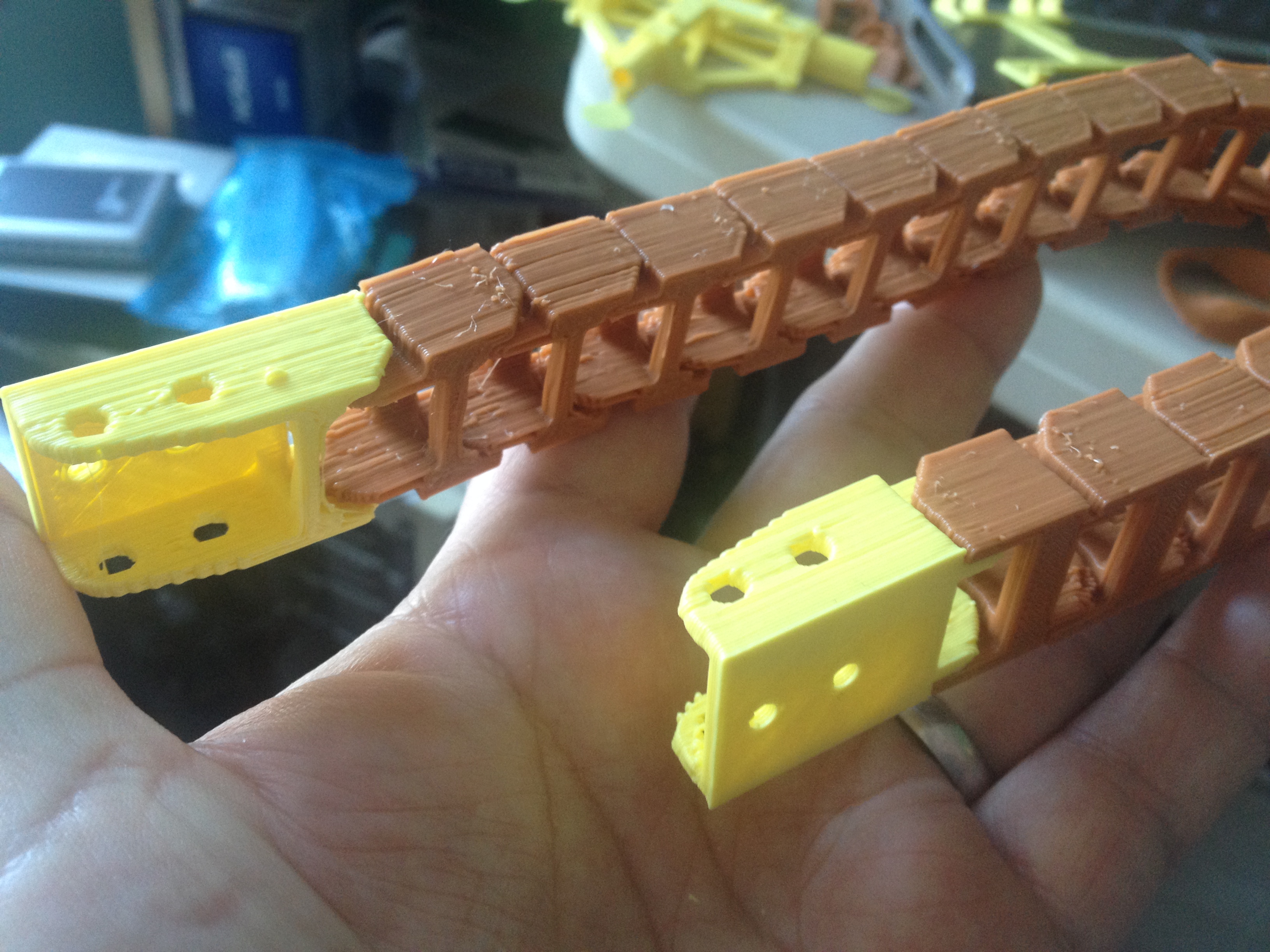
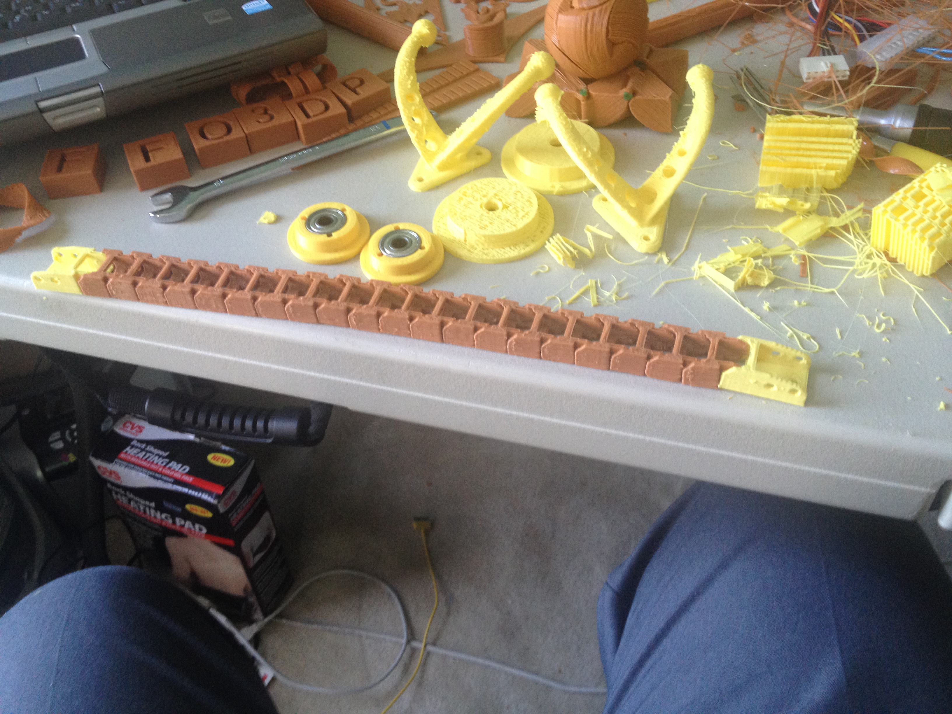
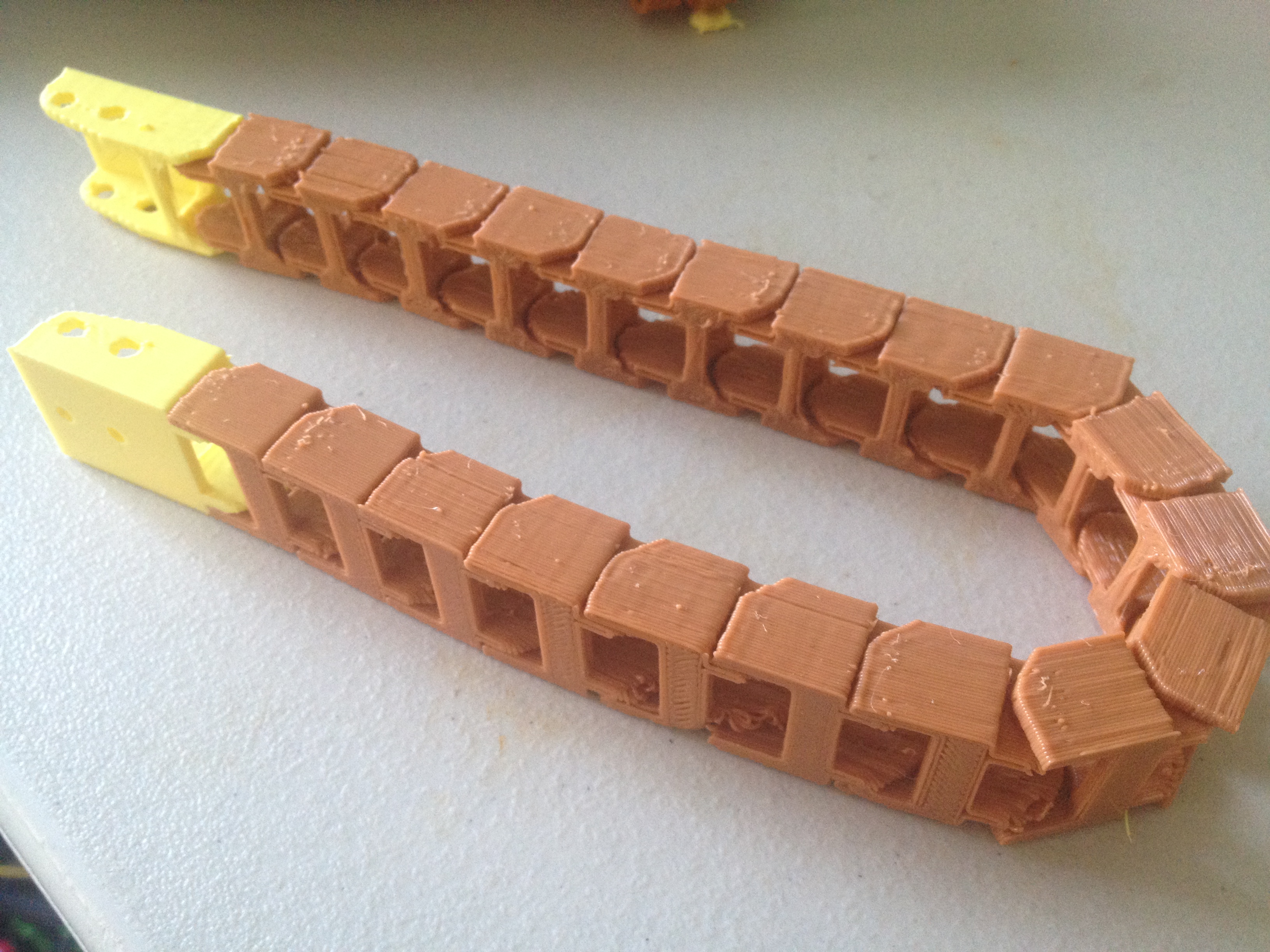
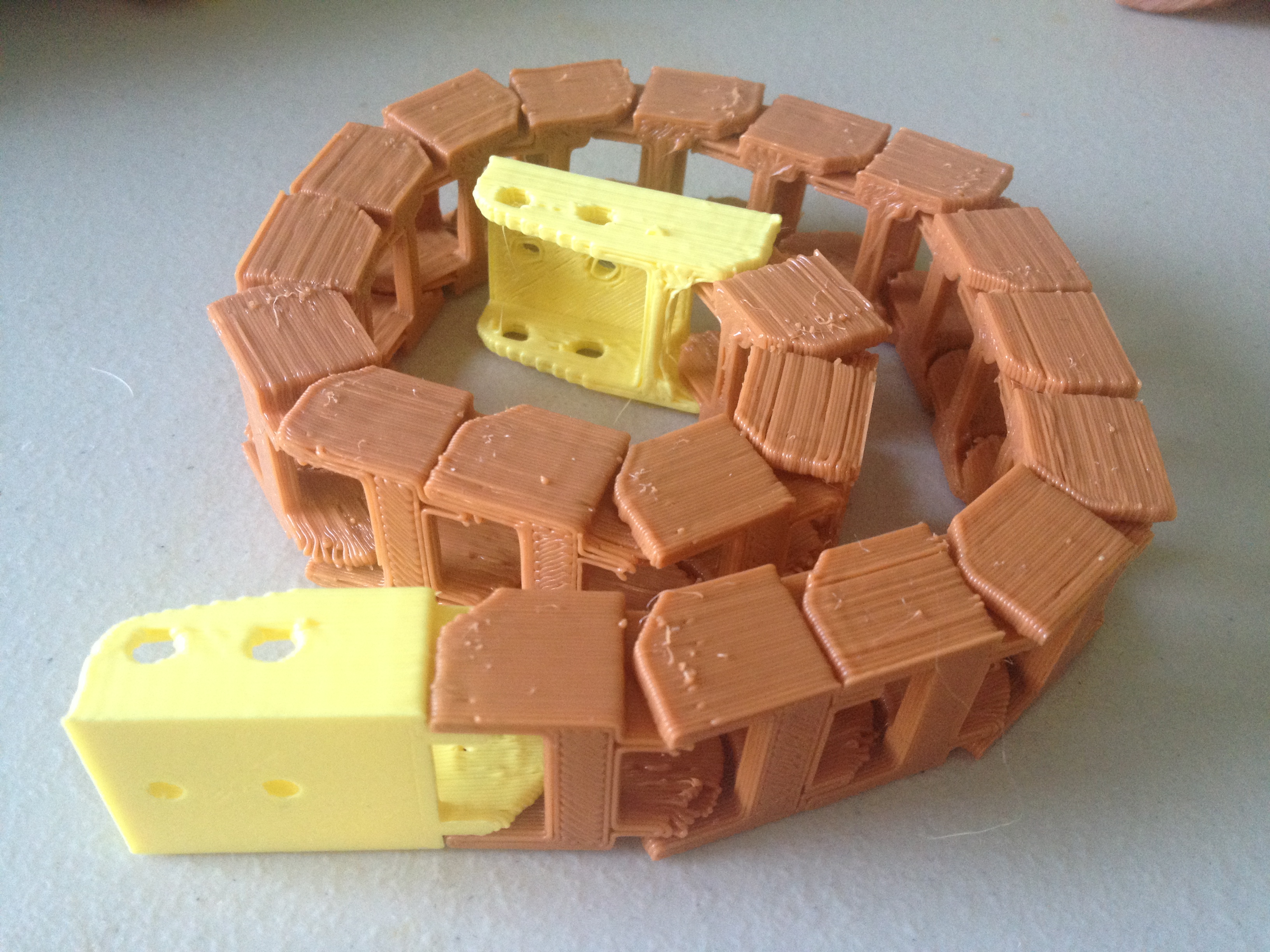
Clip, xbox one smartglass mount, End pieces for cable chain – February 22, 2014
I tried three things this day. The first was a Clip. I was curious to see if this would work. It almost/sorta did. It wasn’t incredibly strong, but it did have a springy clip behavior, as it was supposed to:
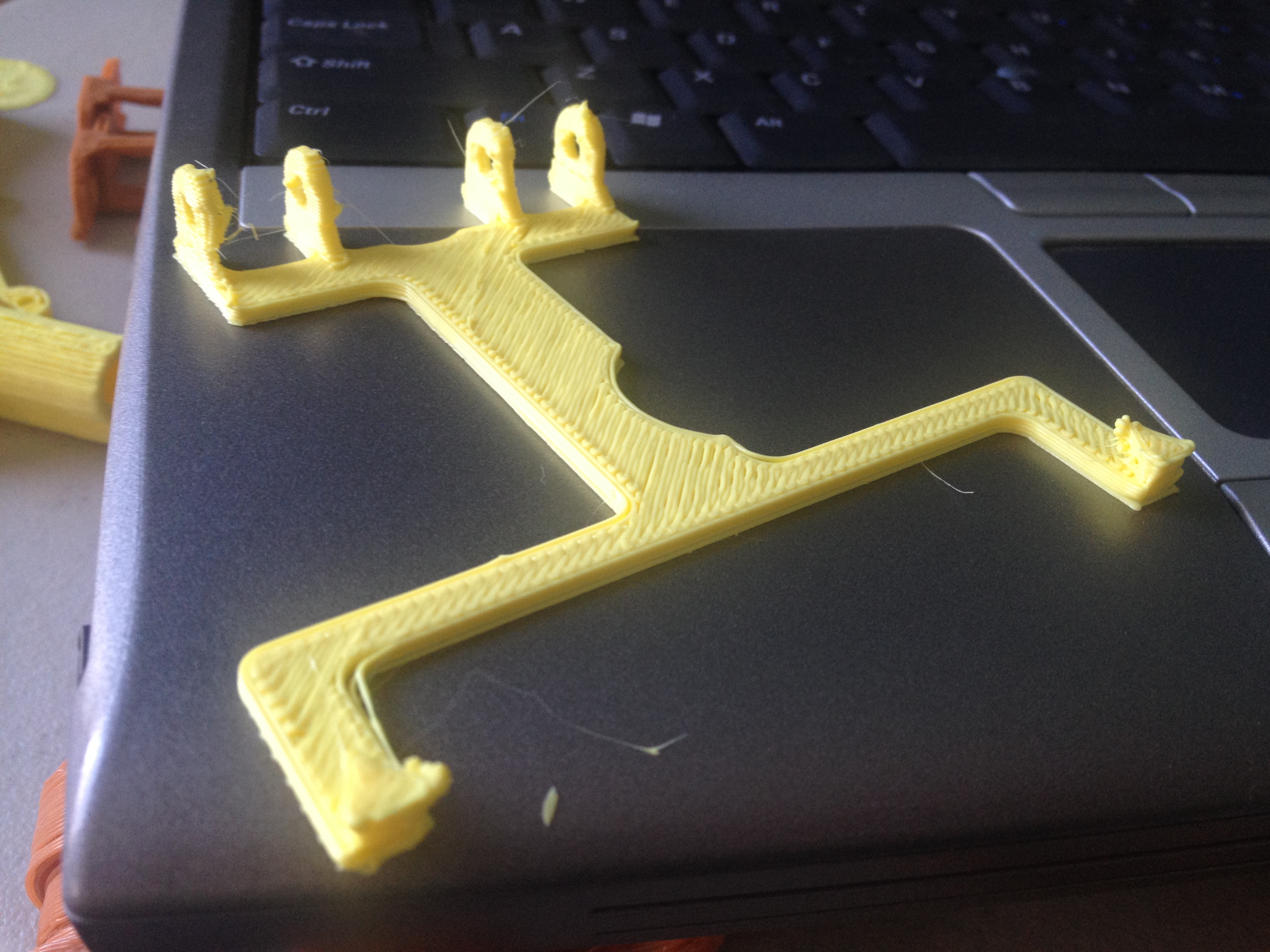
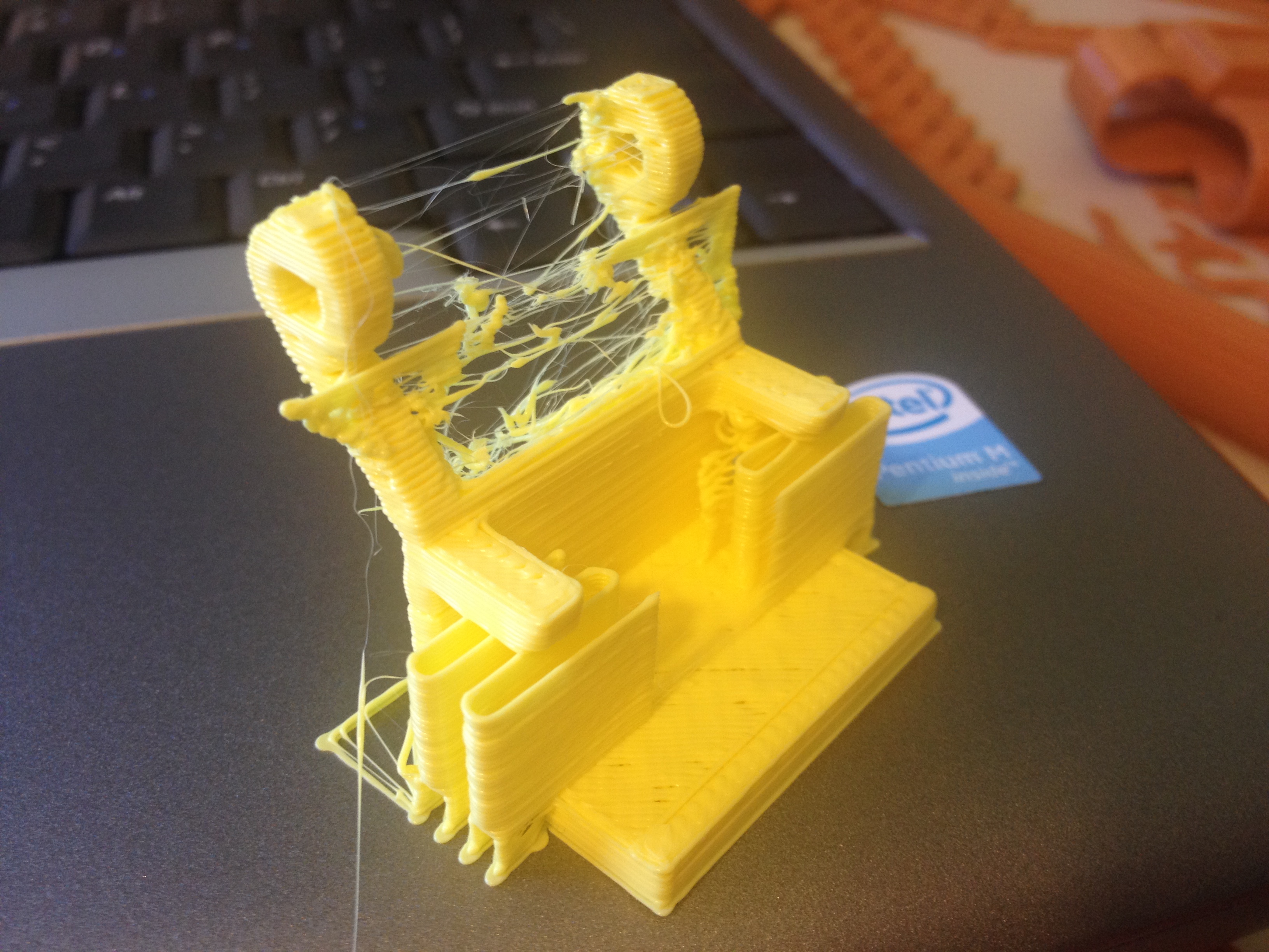
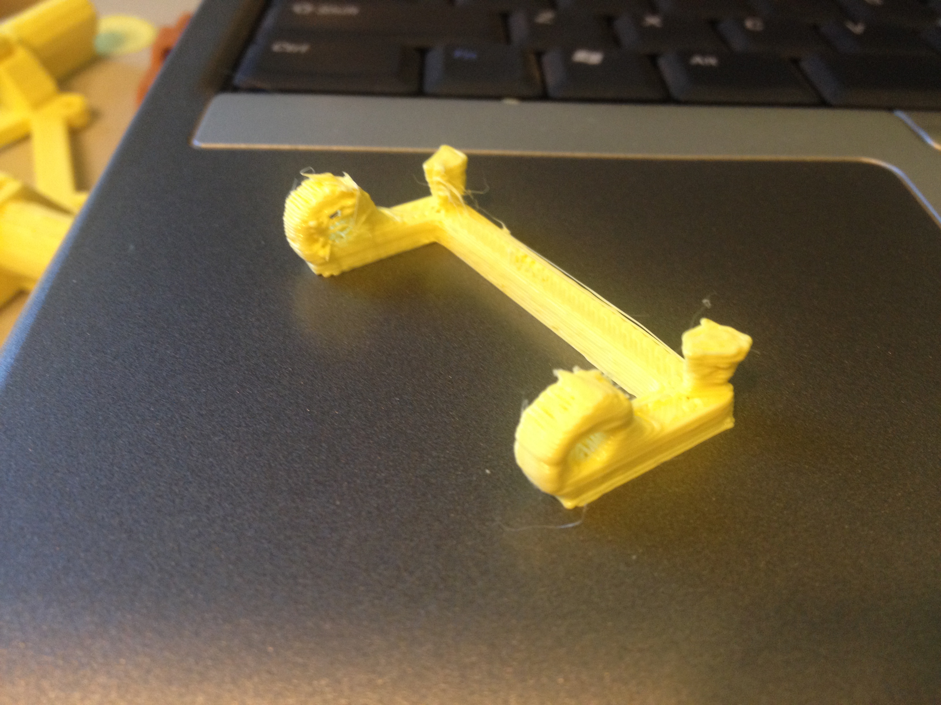
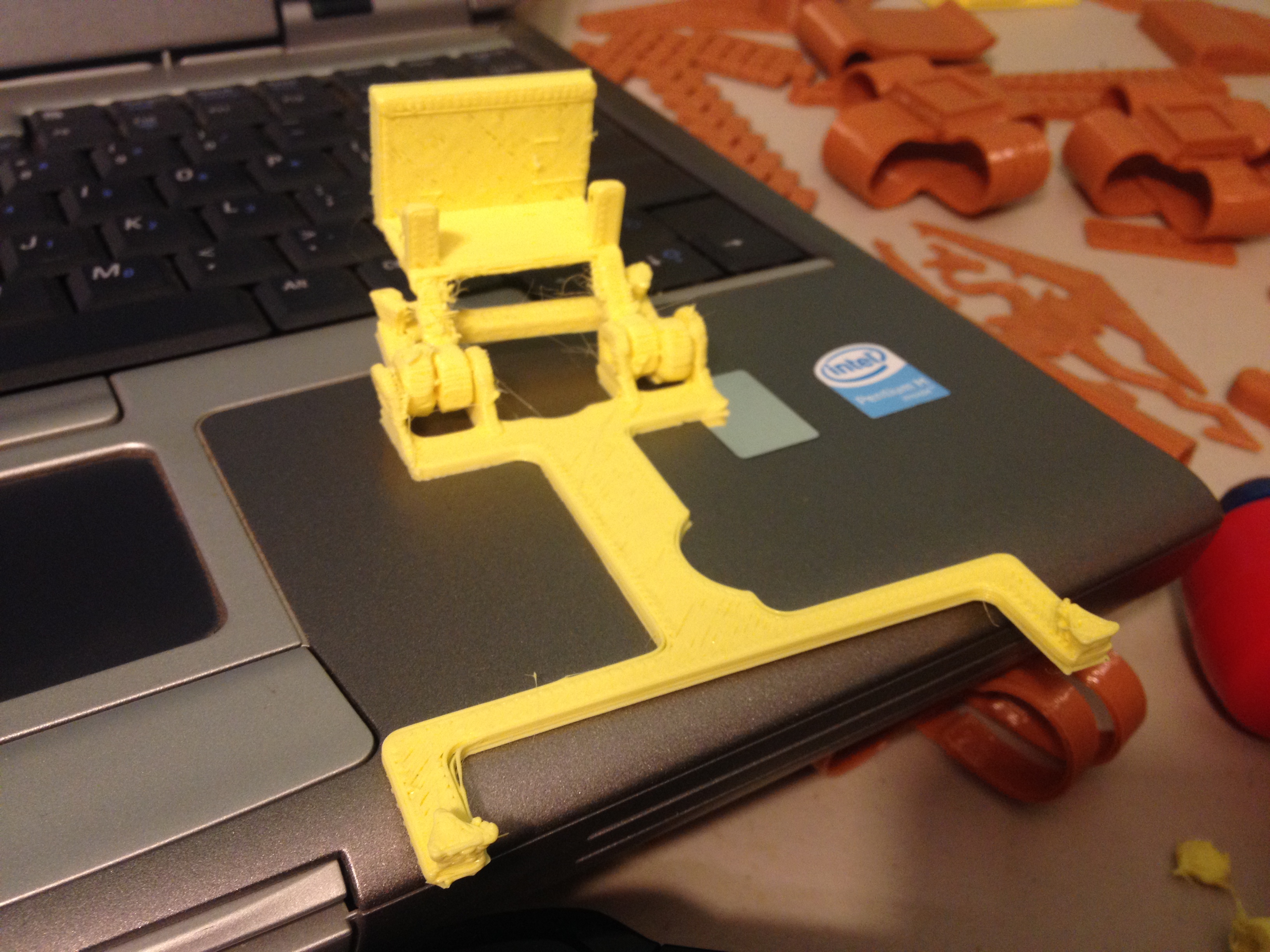
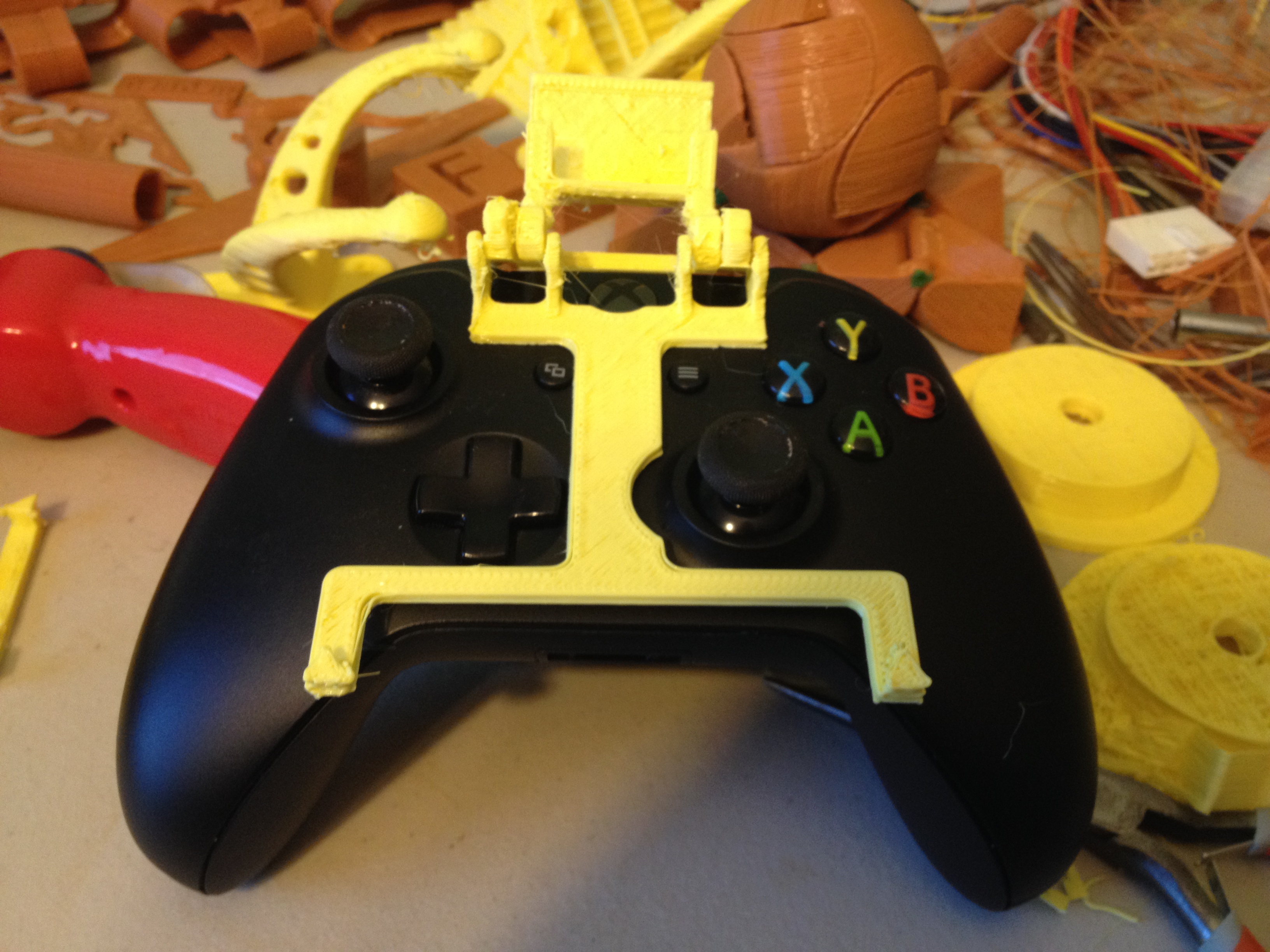
Next, I saw someone had made a mount to hold your smartphone over your Xbox One game controller, so you could run the SmartGlass app and have an alternate display for your controller. I tried printing that, the xbox one smartglass mount:
Eh.. My prints of it weren’t the strongest, so I never ended up actually using it.
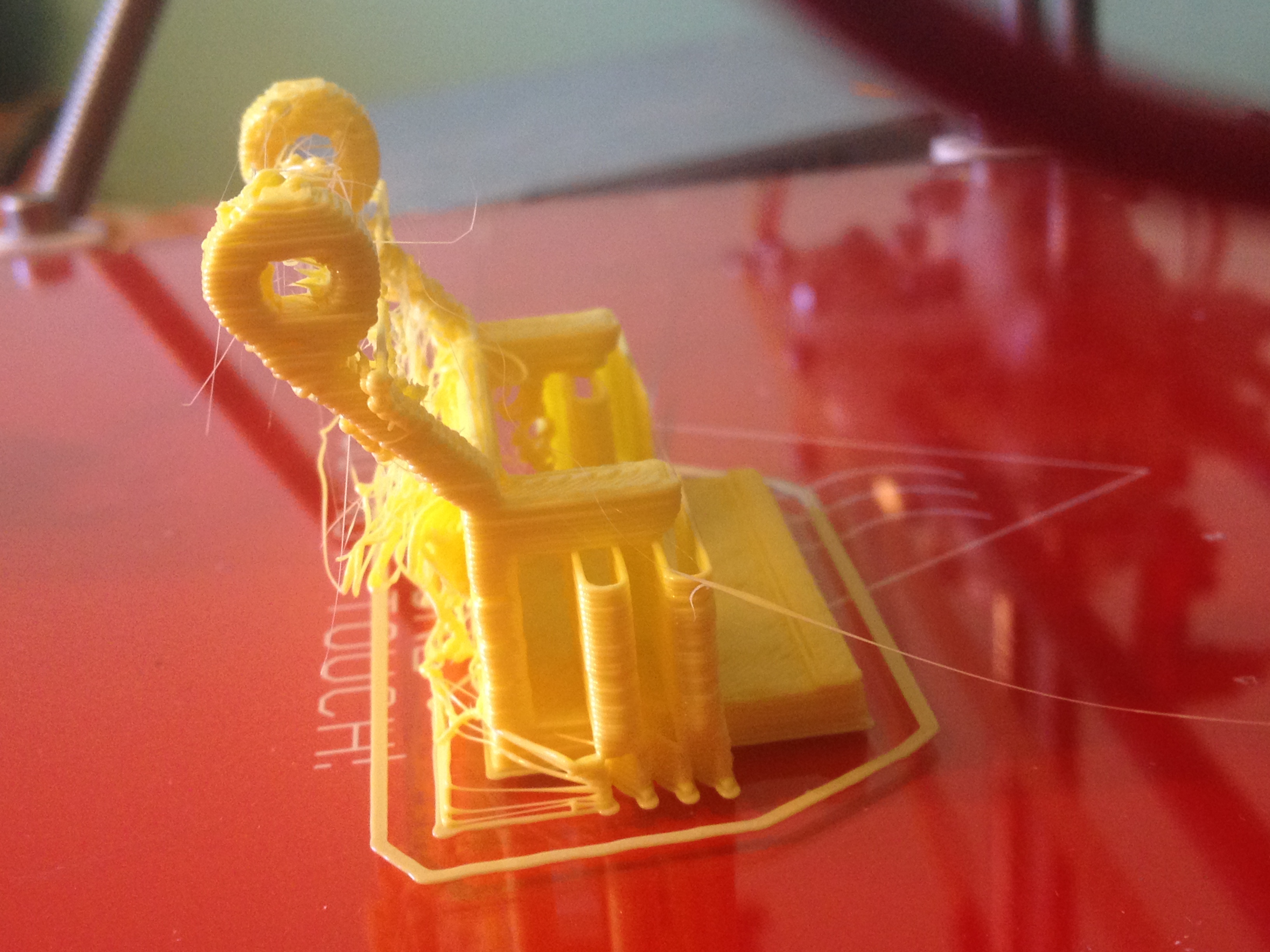
And I also printed end pieces to the Cable Chain I’d printed previously. Here they are, along with all of the pieces of the Cable Chain that I’d snuck in over the past 9 days:
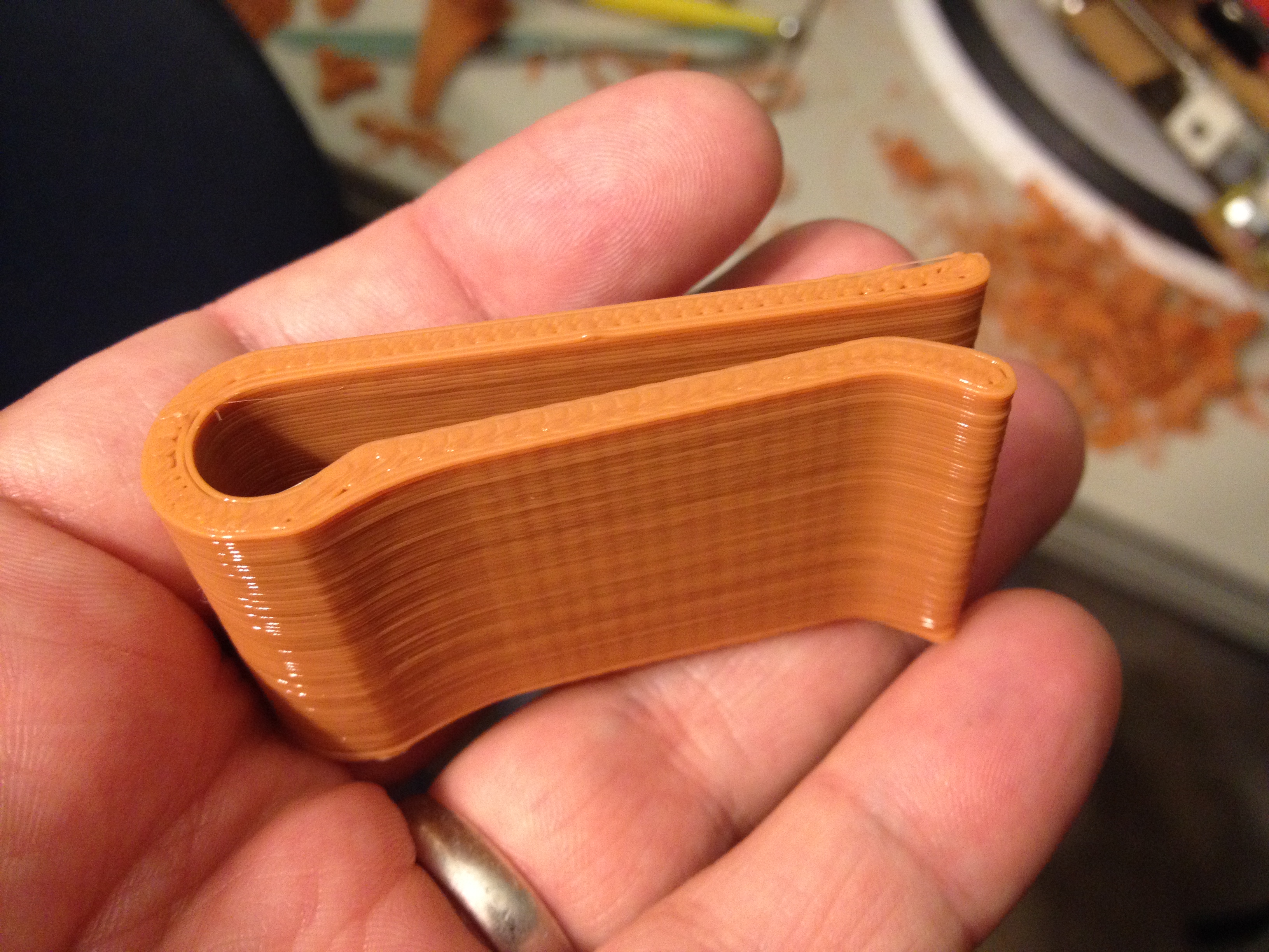
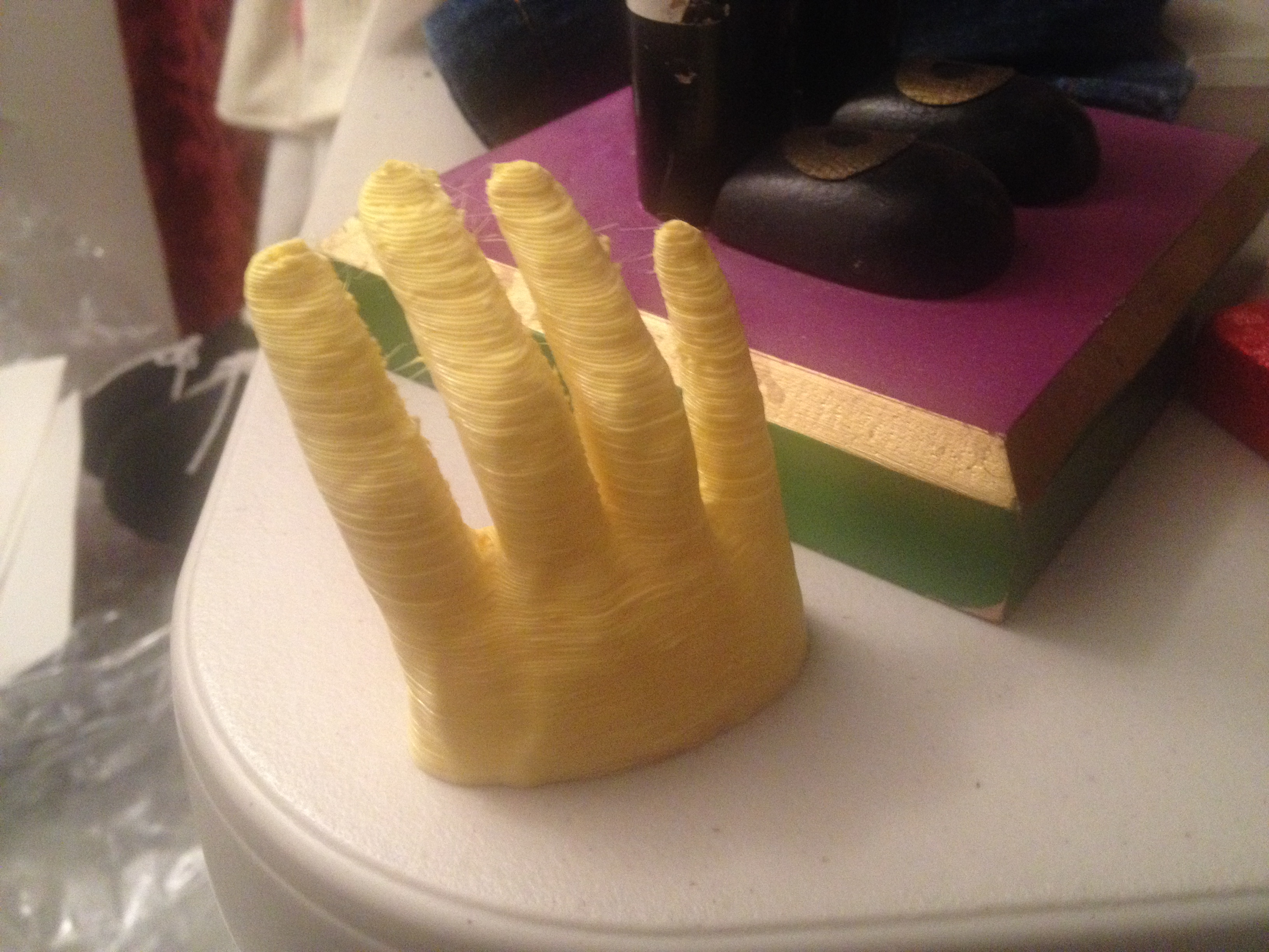
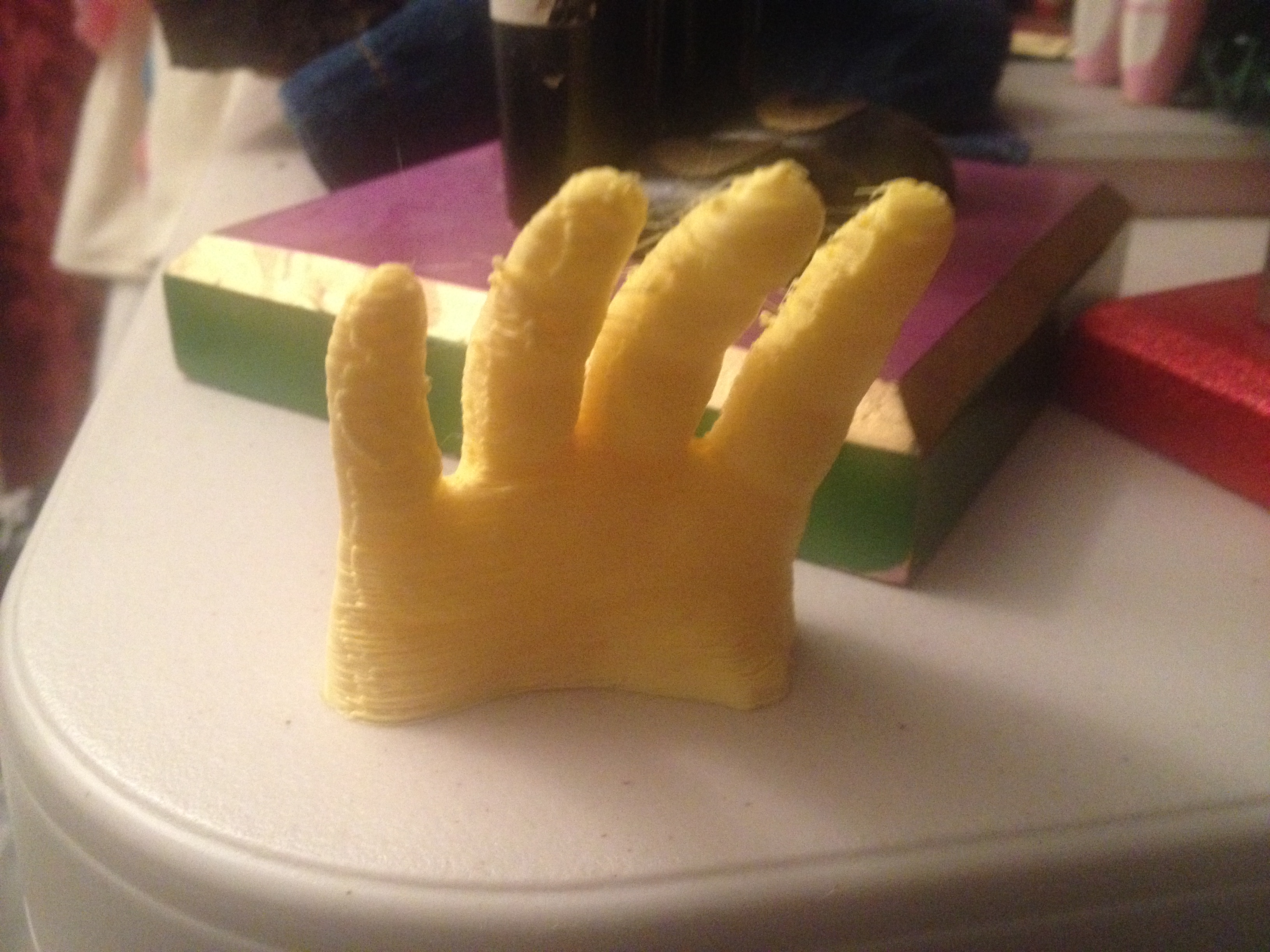
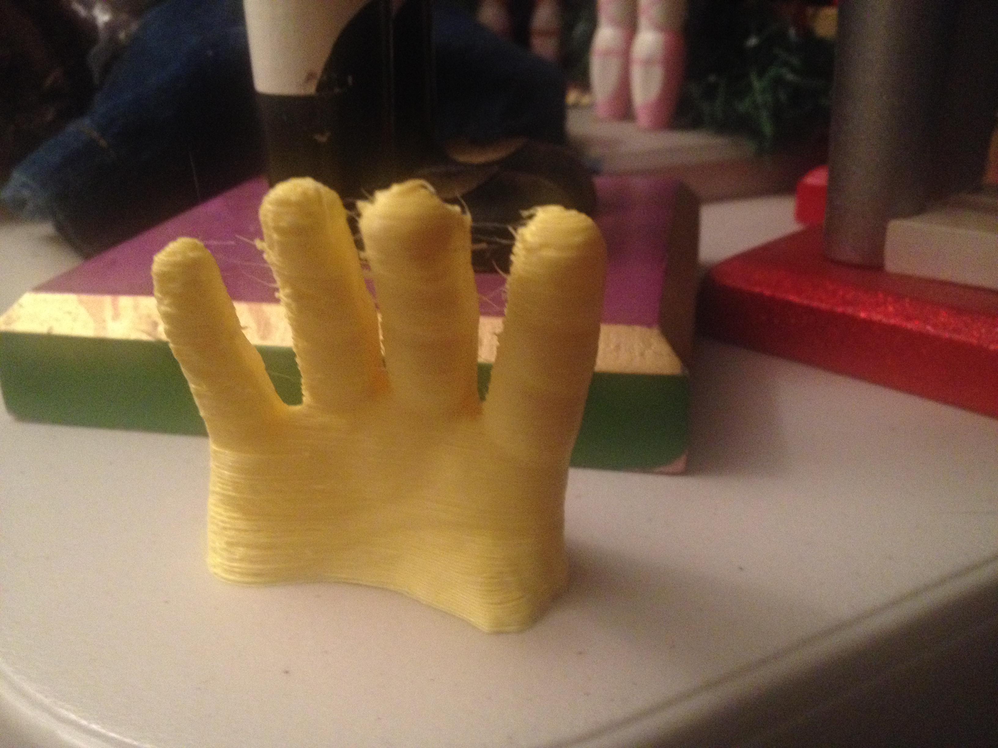
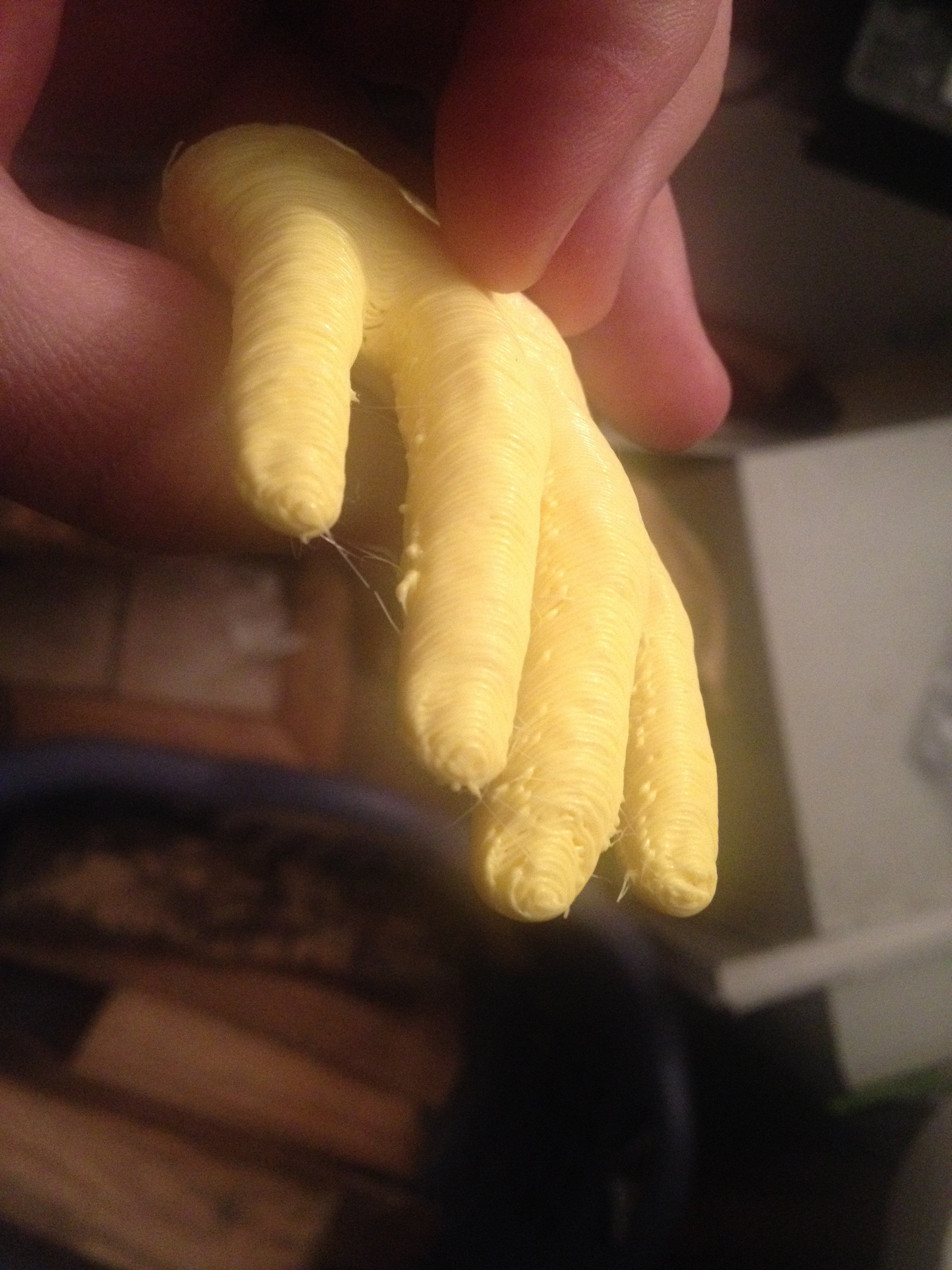
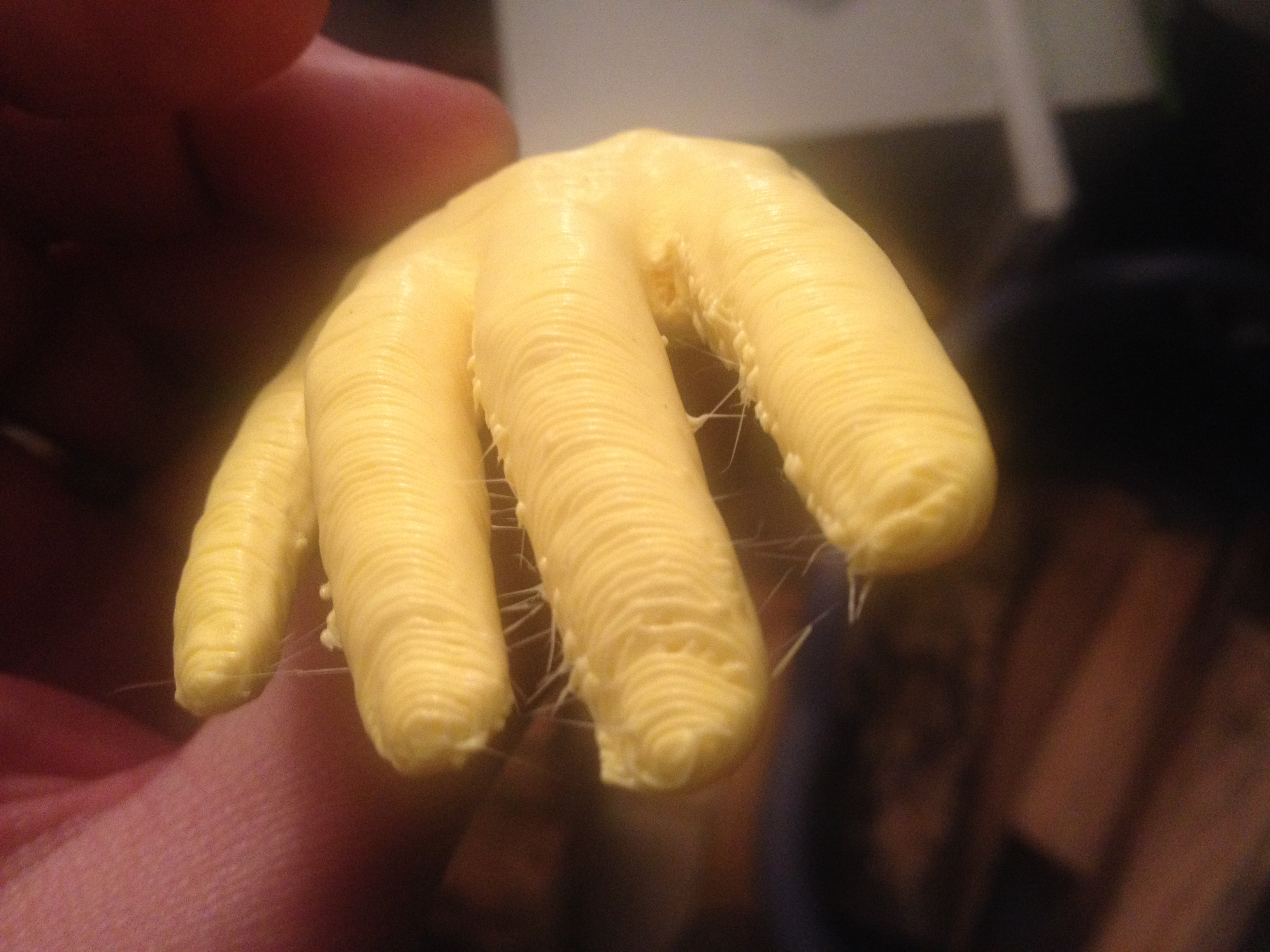
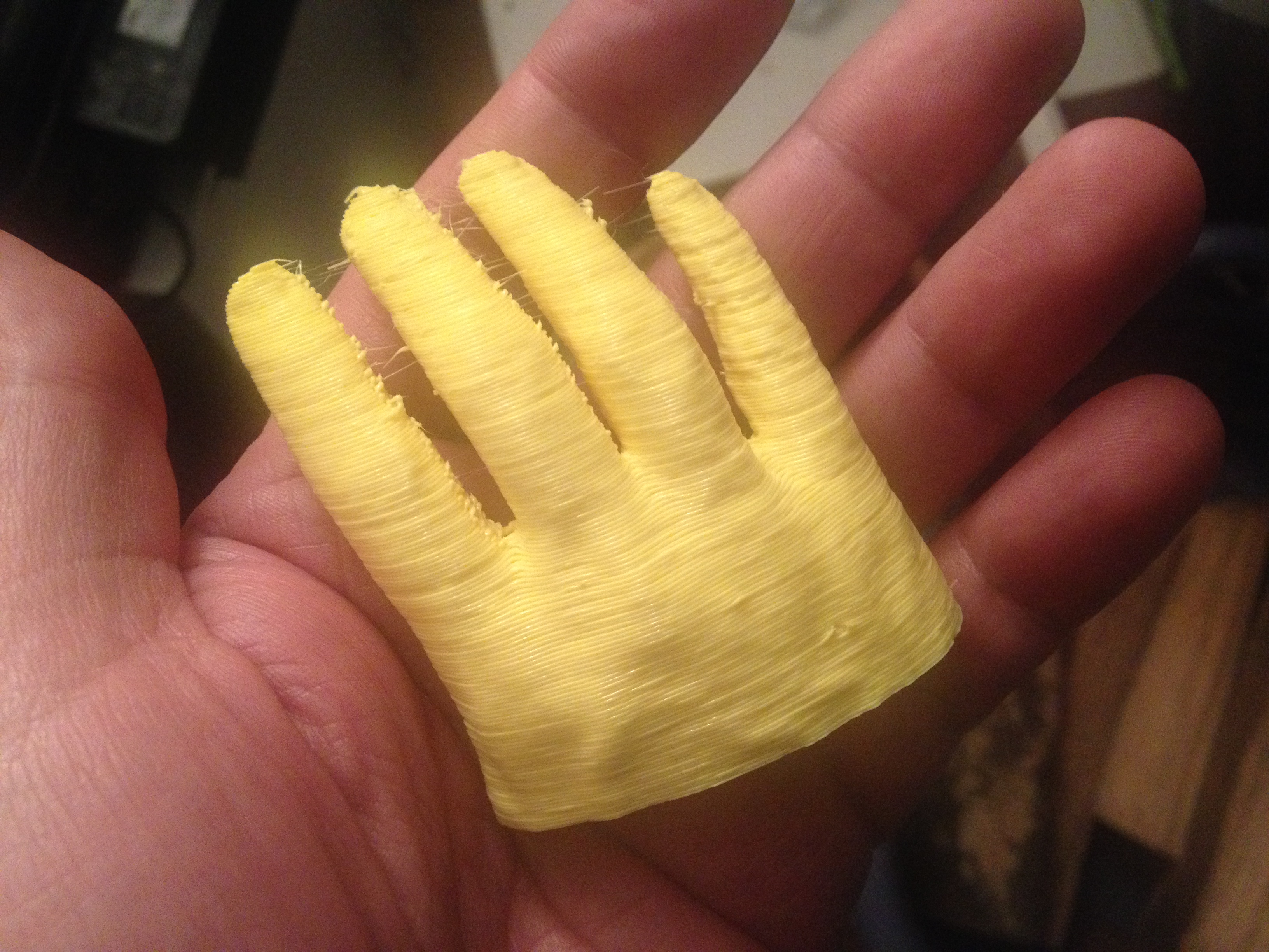
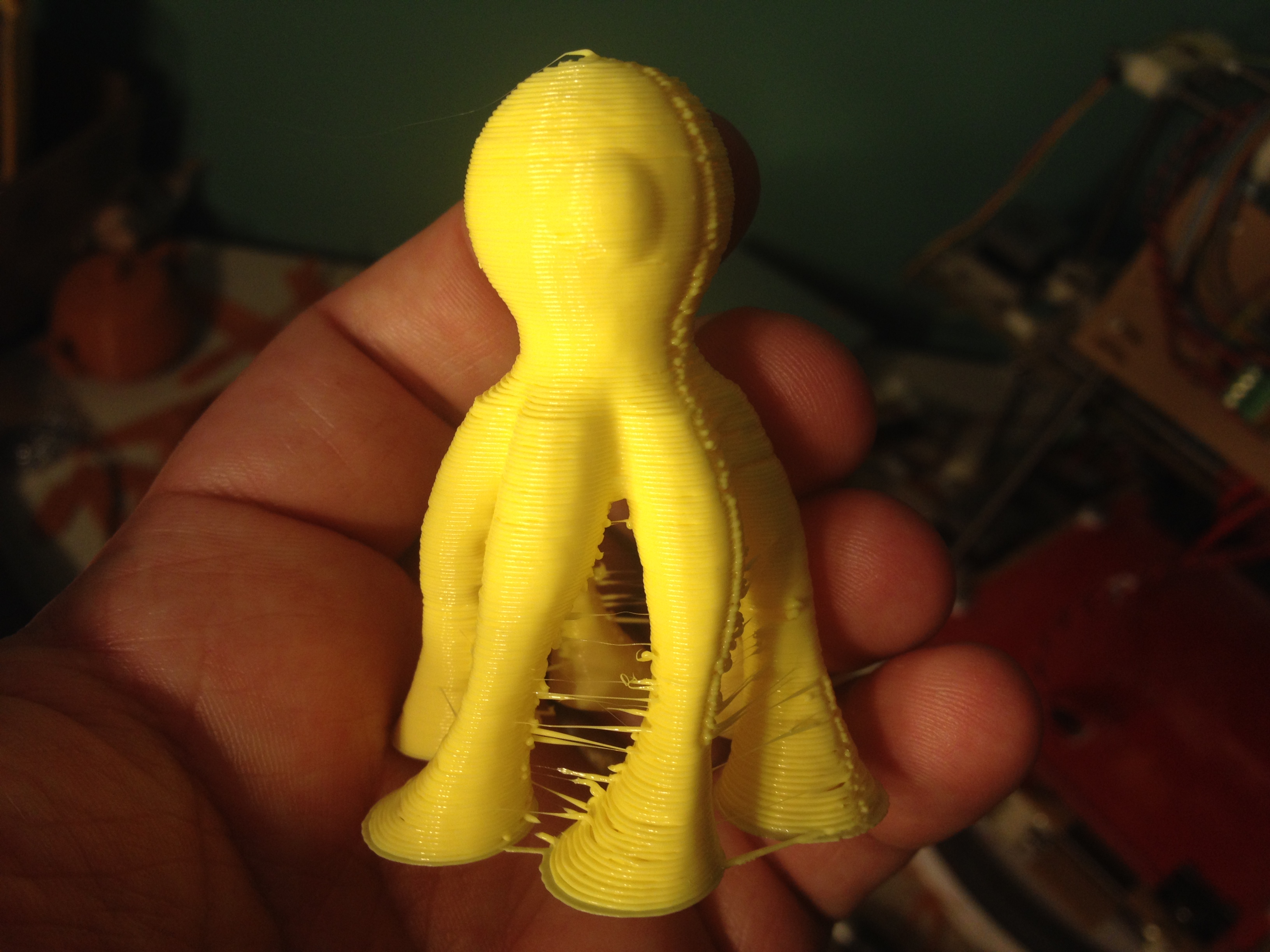
Talk to the Hand (maybe too tall?) – February 23, 2014
I love this next print – Talk to the Hand – Flat base. I saw Chris Connelly print one of these at Makerfaire five months earlier (his was larger), and it was flat out creepy (it triggered something in the mind about recognizing a person).
…and here’s a picture that betrays how small my version of that print really is:
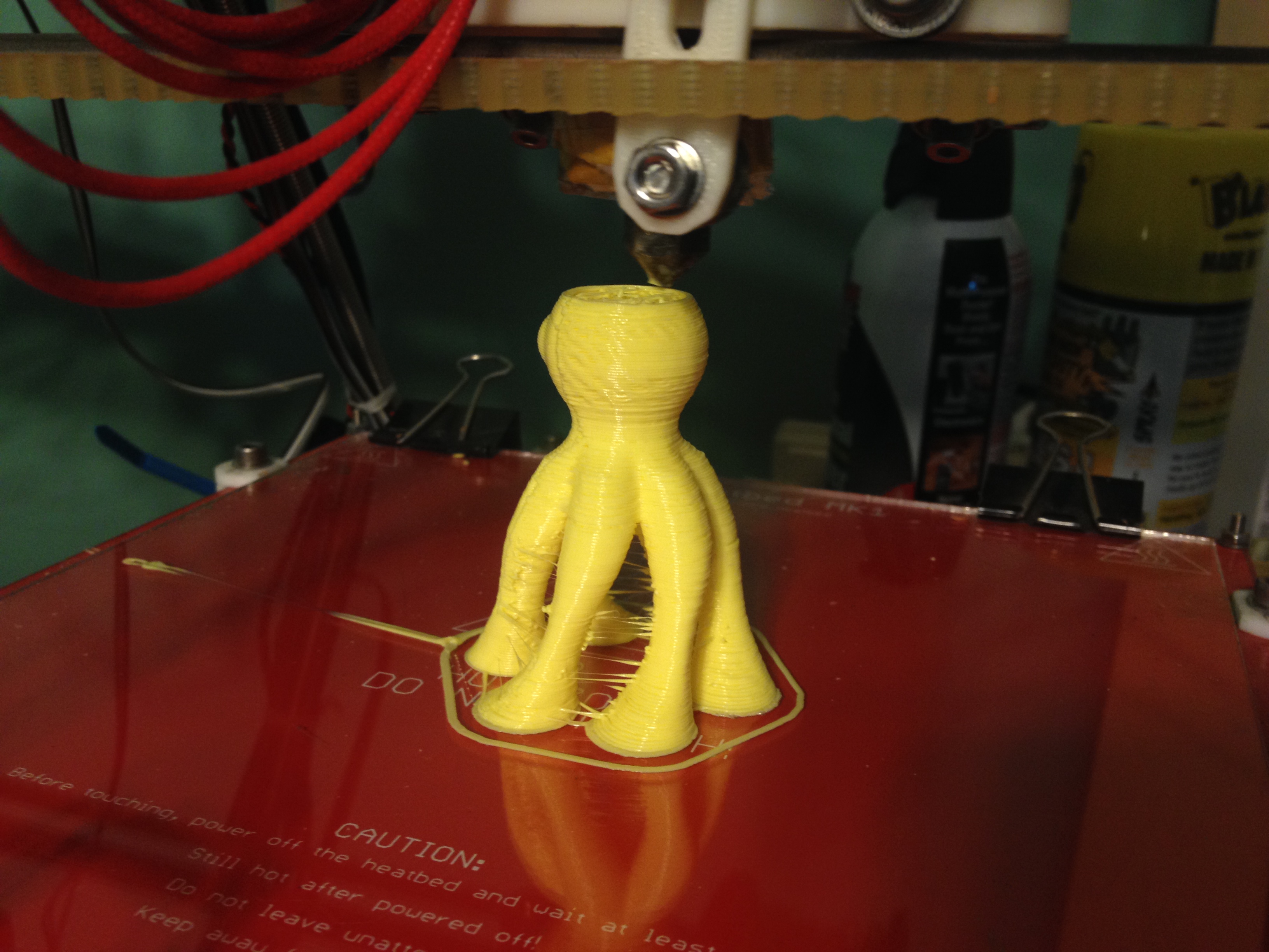
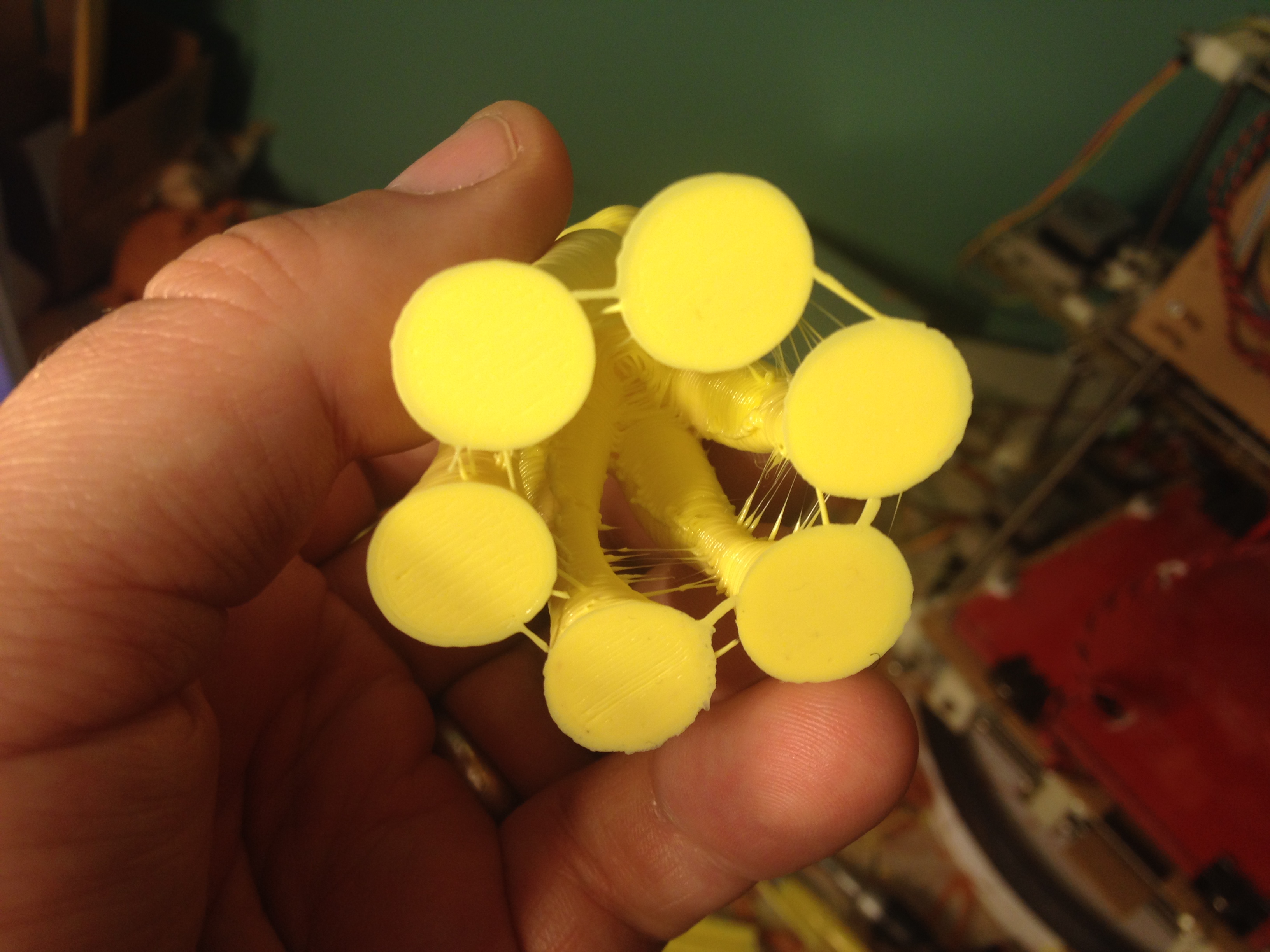
Thing1 – February 24, 2014
Here’s a little eyeball-monster called Thing1 that I’d seen people printing before (I think I had printed one of these at the end of Makerfaire five months prior to this):
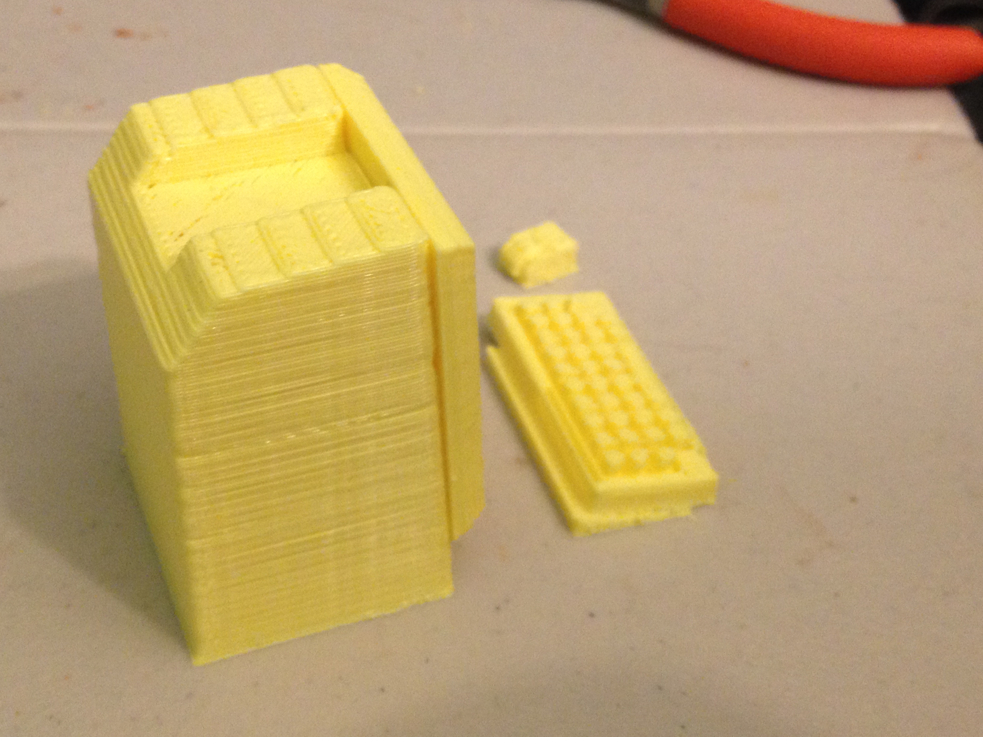
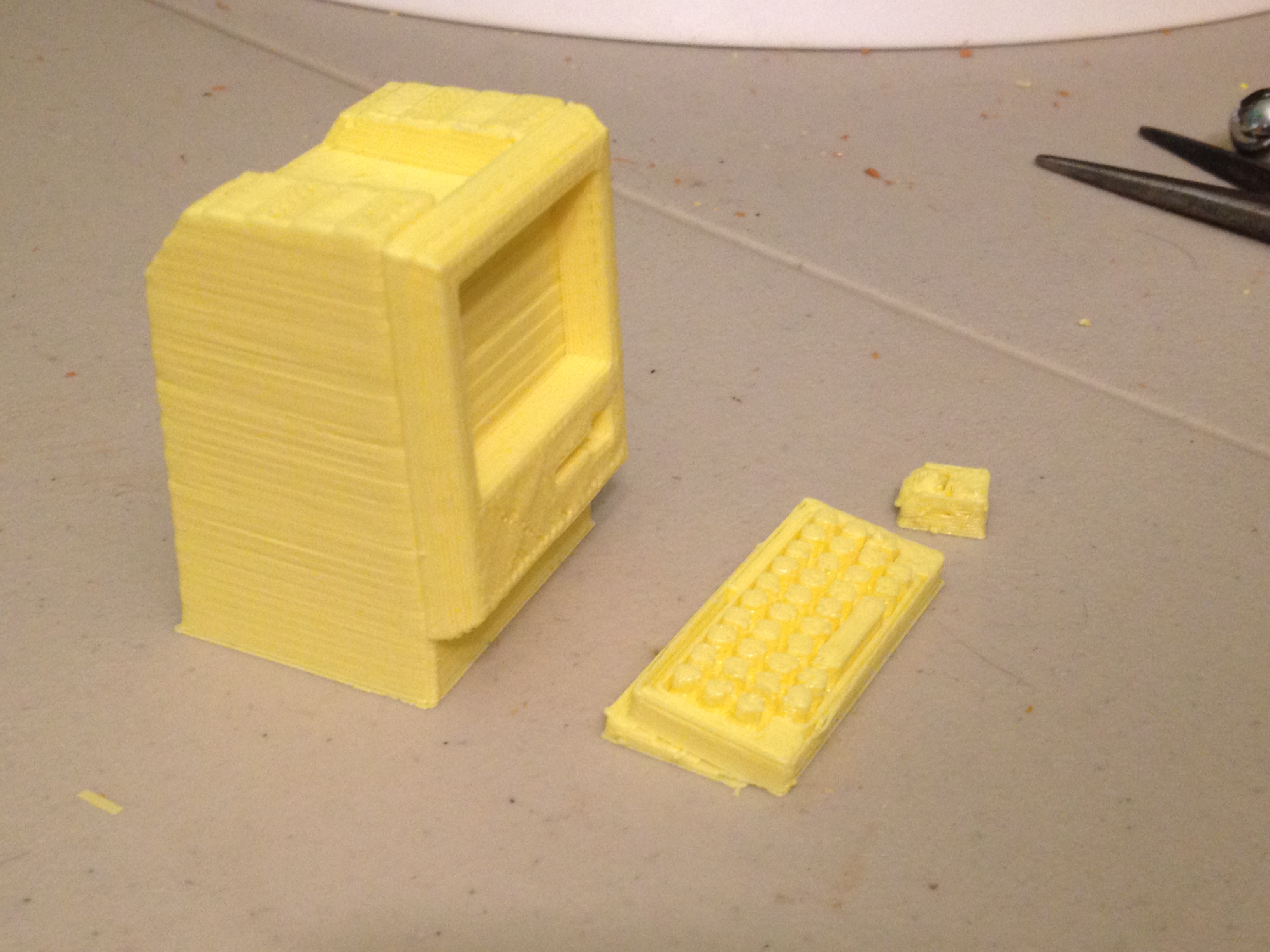
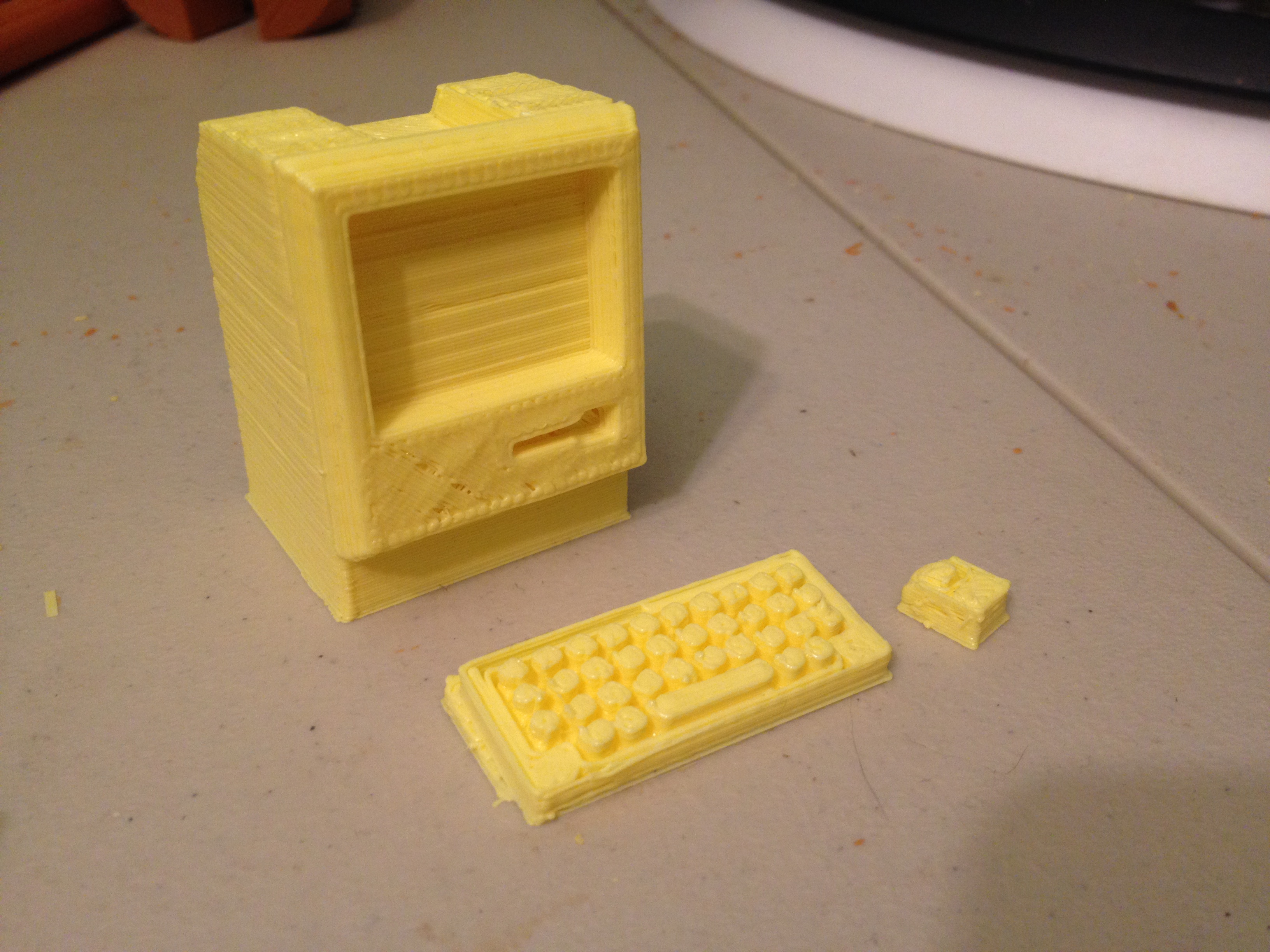
Mini Apple Macintosh – February 25, 2014
Like the Apple II before it, I printed out another one of the computers I’ve owned – a Mini Apple Macintosh:
(There were little screens and logos you could print out on a paper printer and tape them on.. I did print them, but never got around to attaching them and taking a picture).
The leg joints are printed such that they can actually move. This allows the elephant to stand up, even though it was printed out lying down.
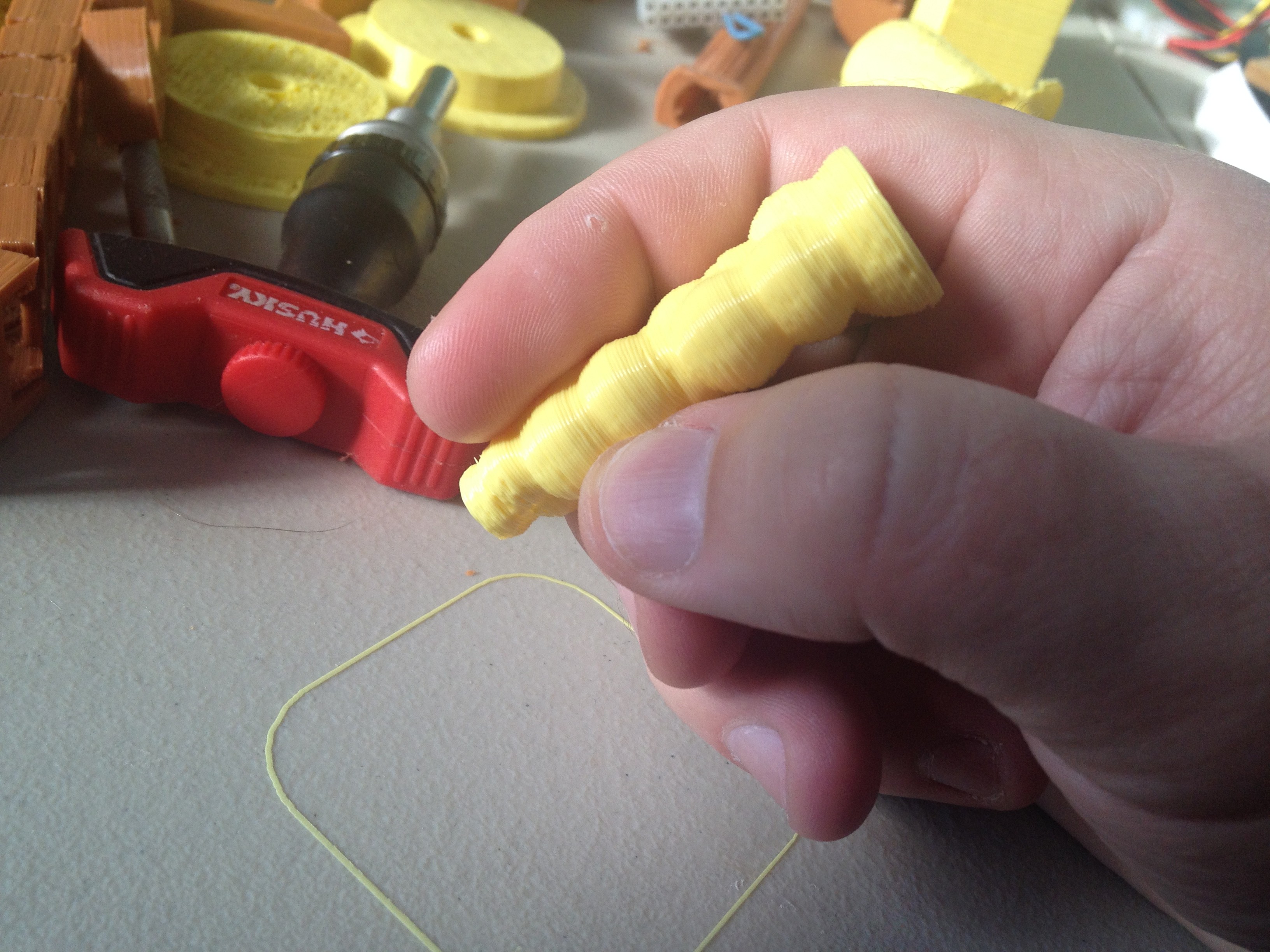
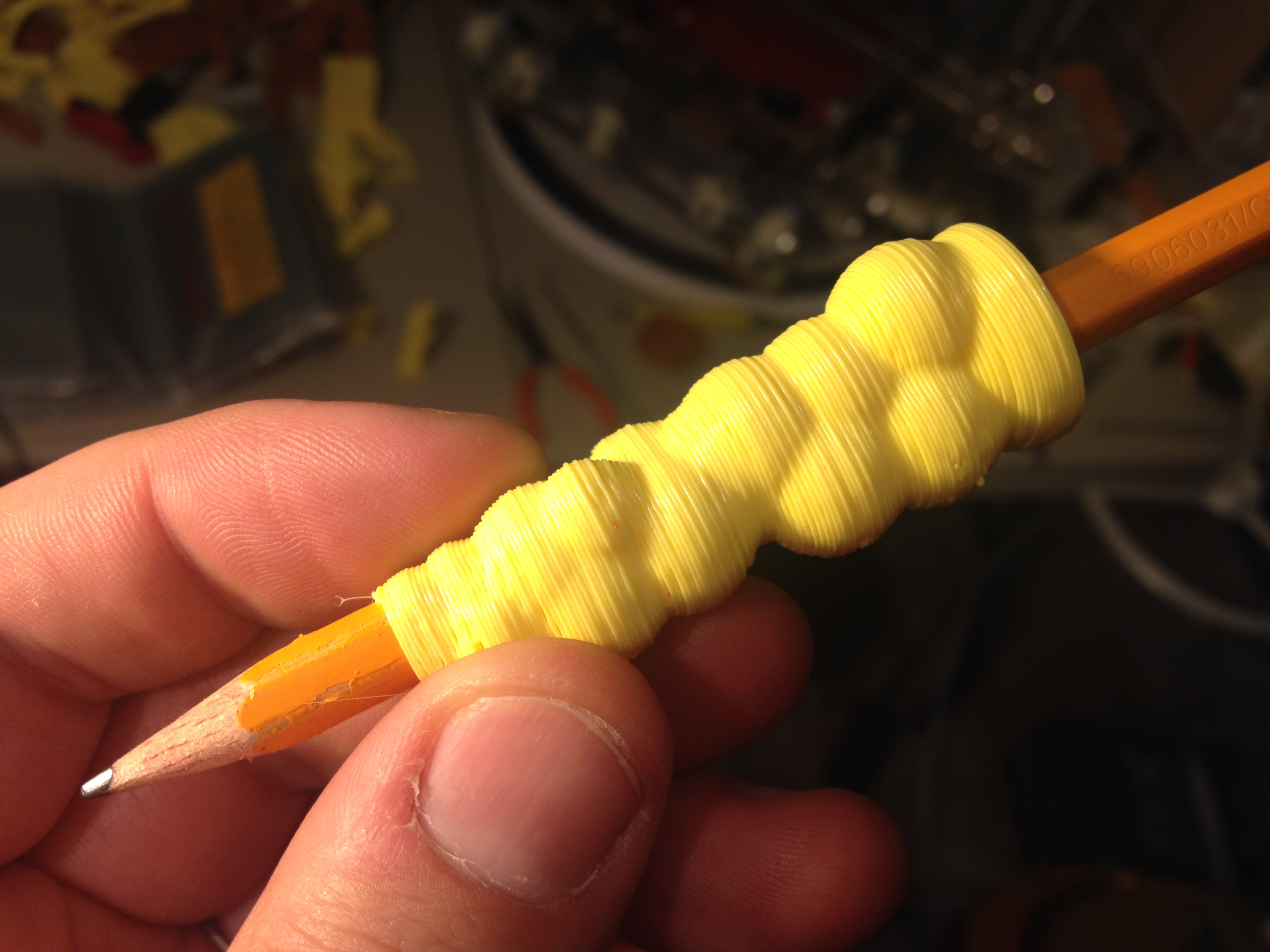
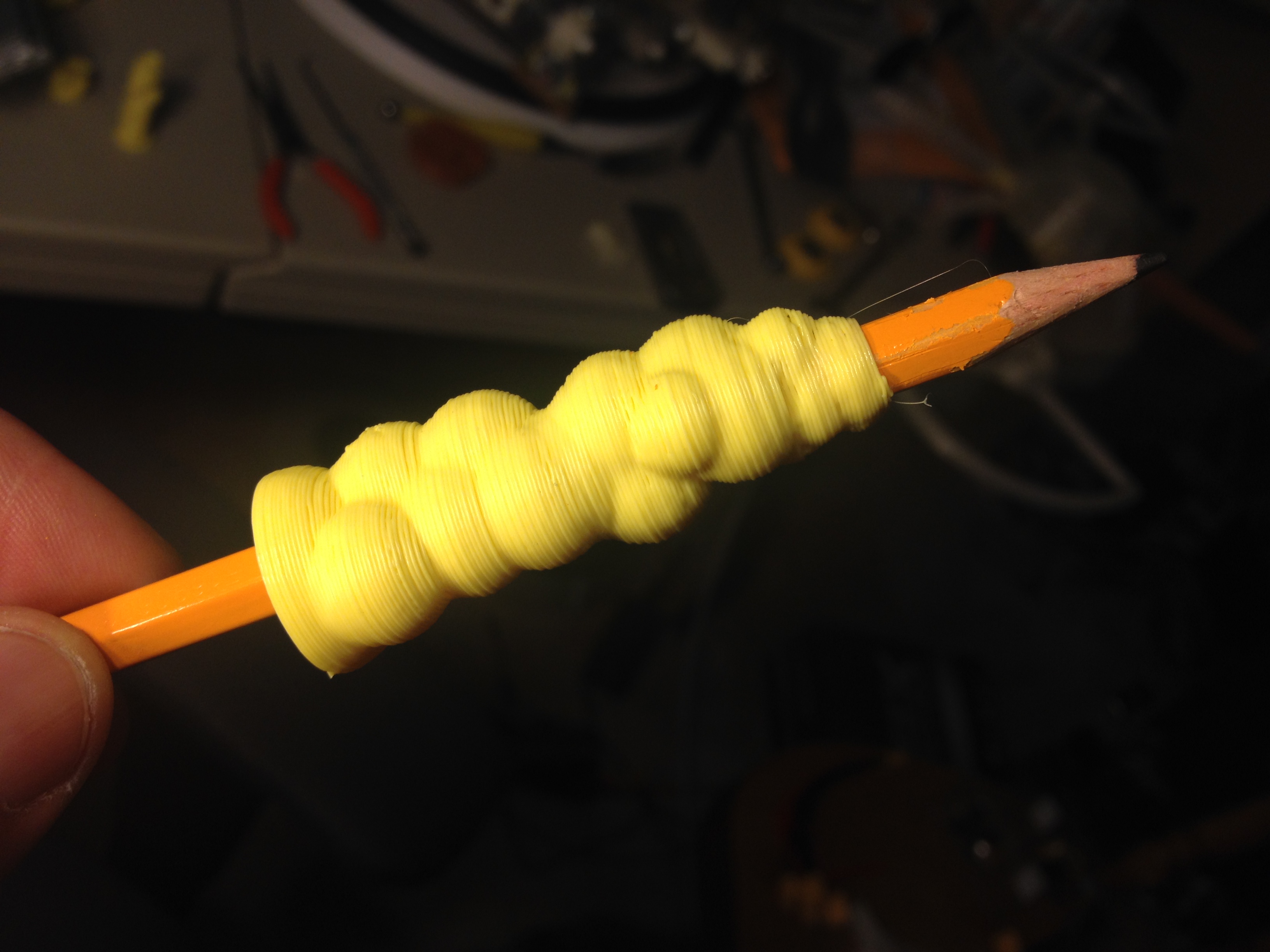
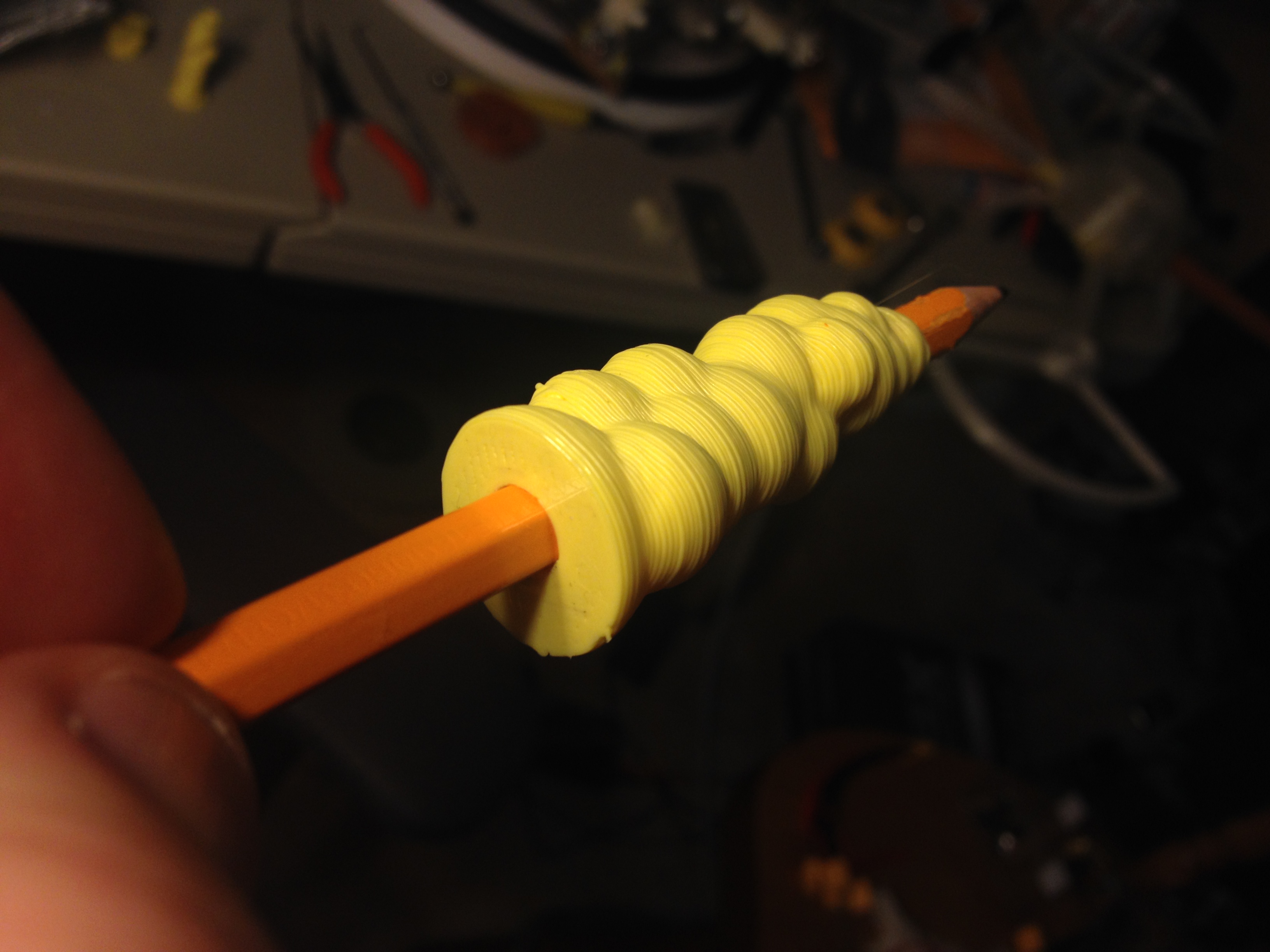
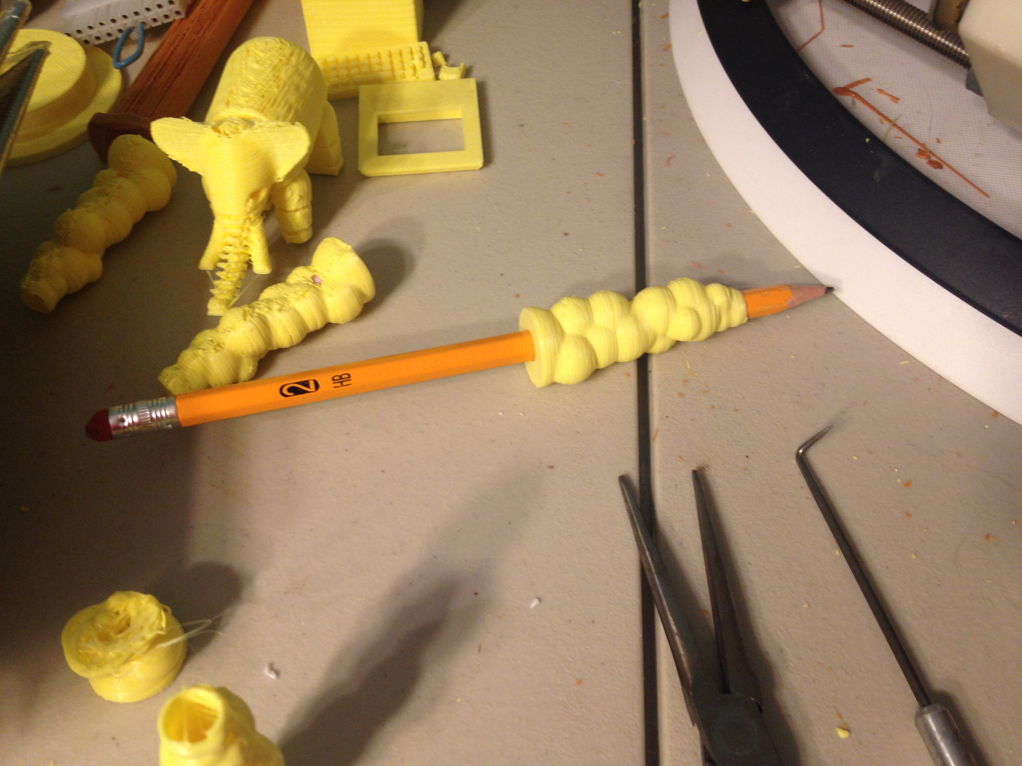
Bubble Pencil Grip – February 27, 2014
Really close to the end here, I saw a grip for a pencil that I thought I’d try out (even though I could never imagine using it). Here is Bubble Pencil Grip:
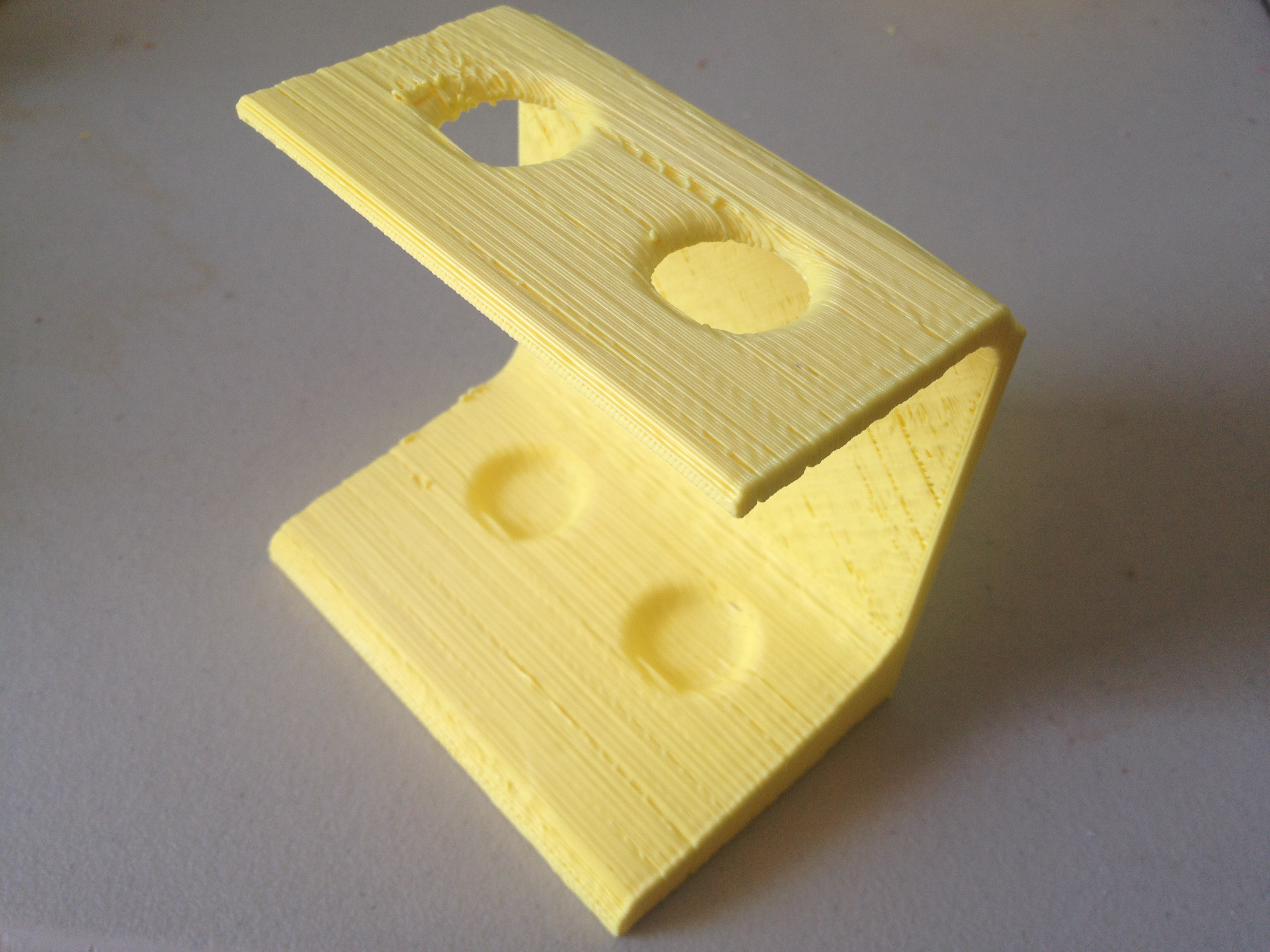
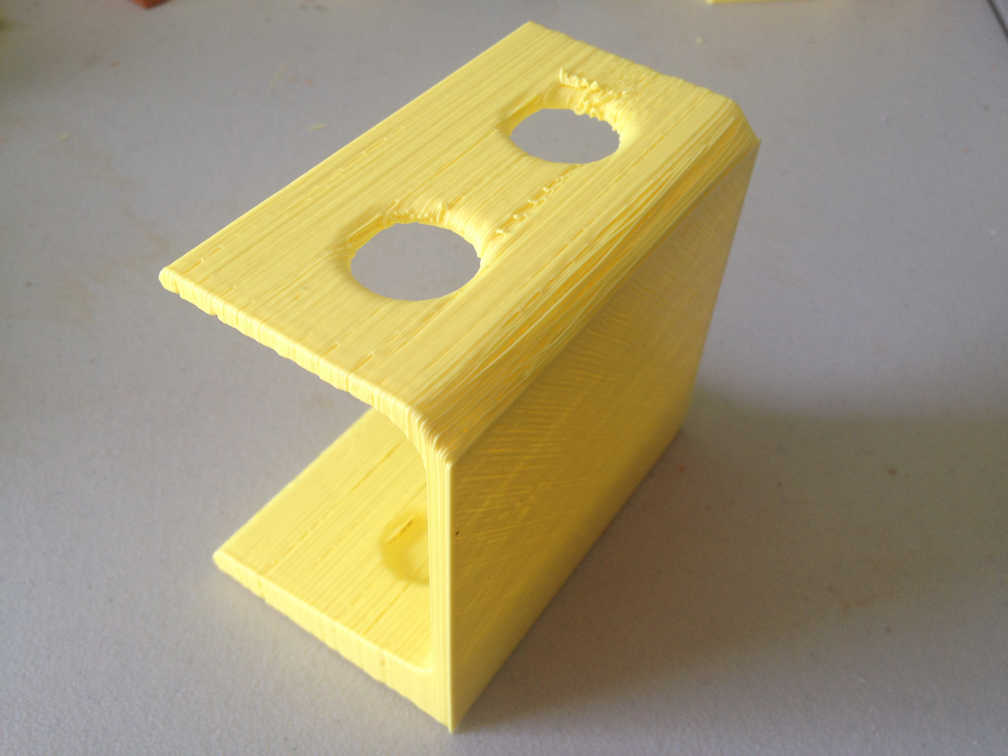
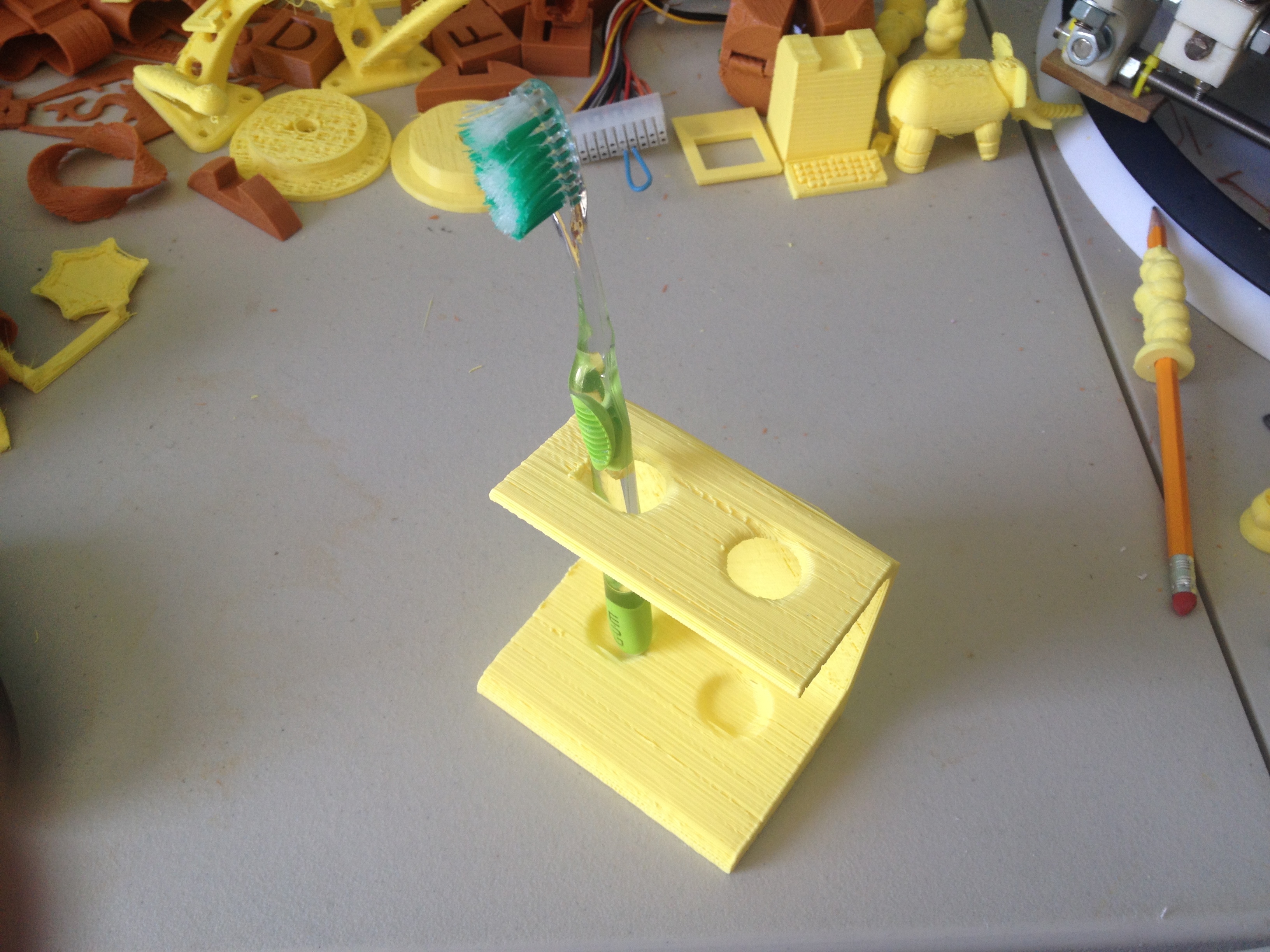
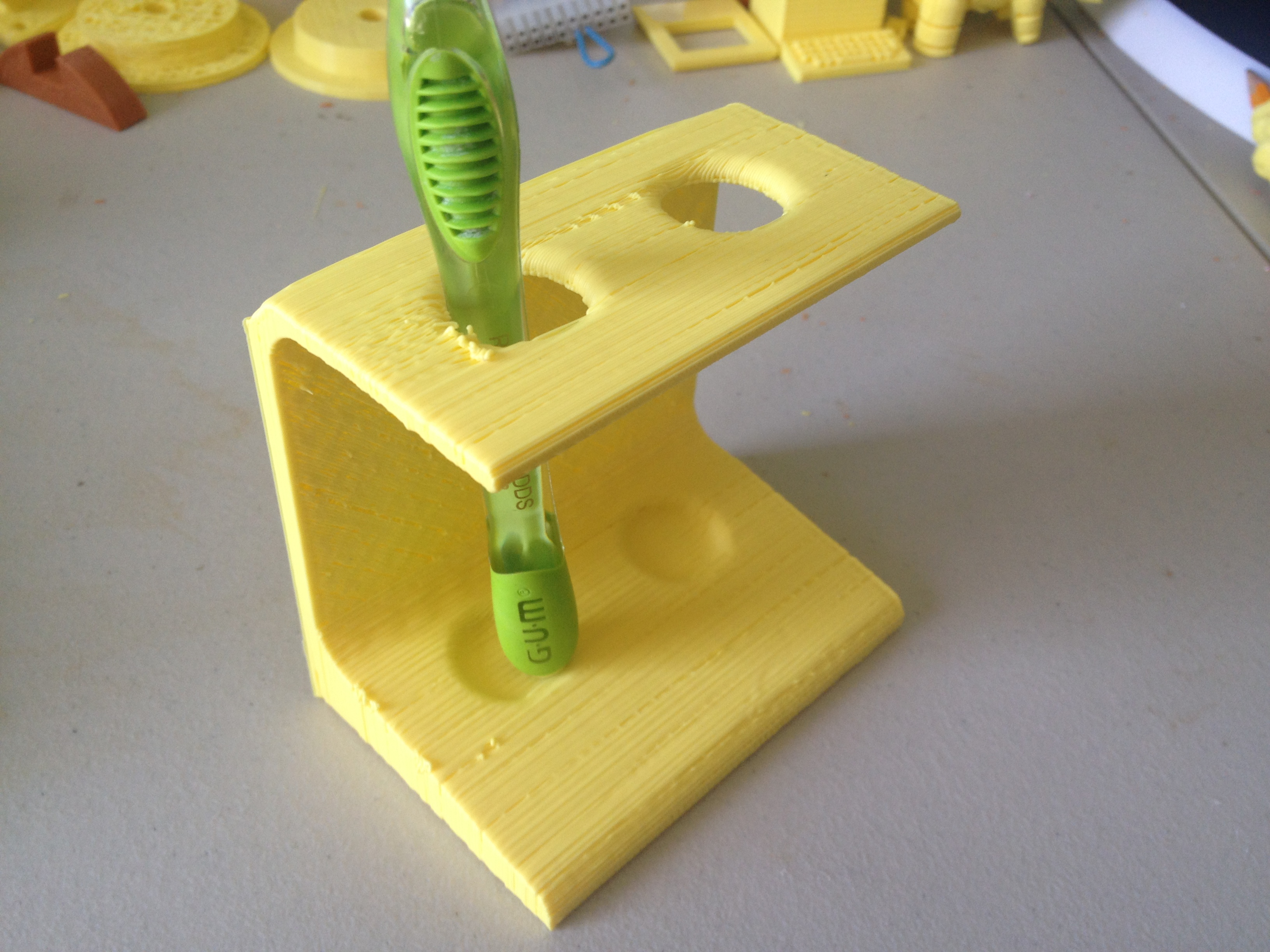
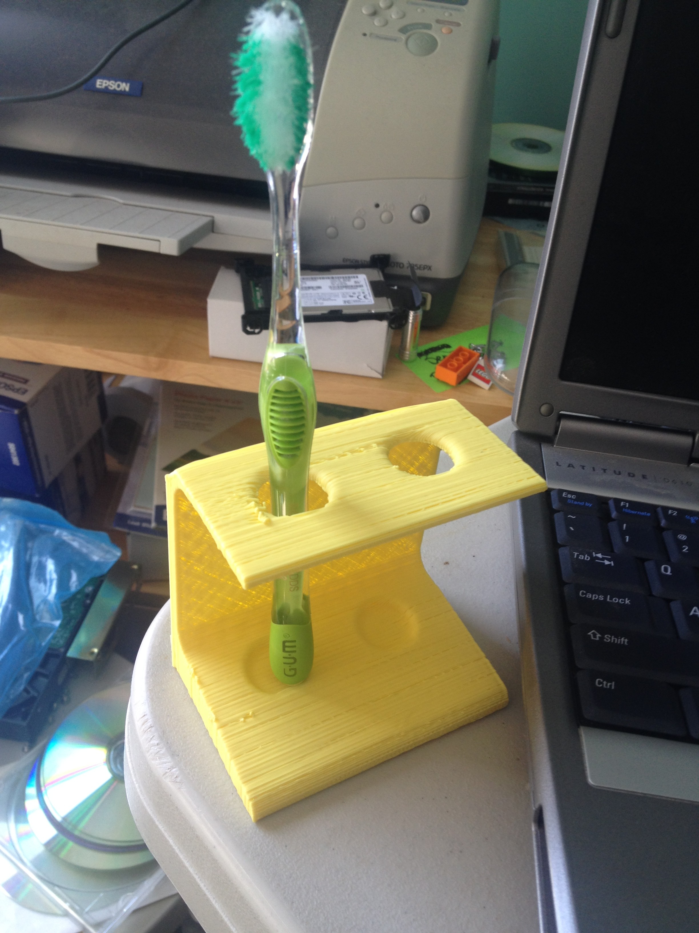
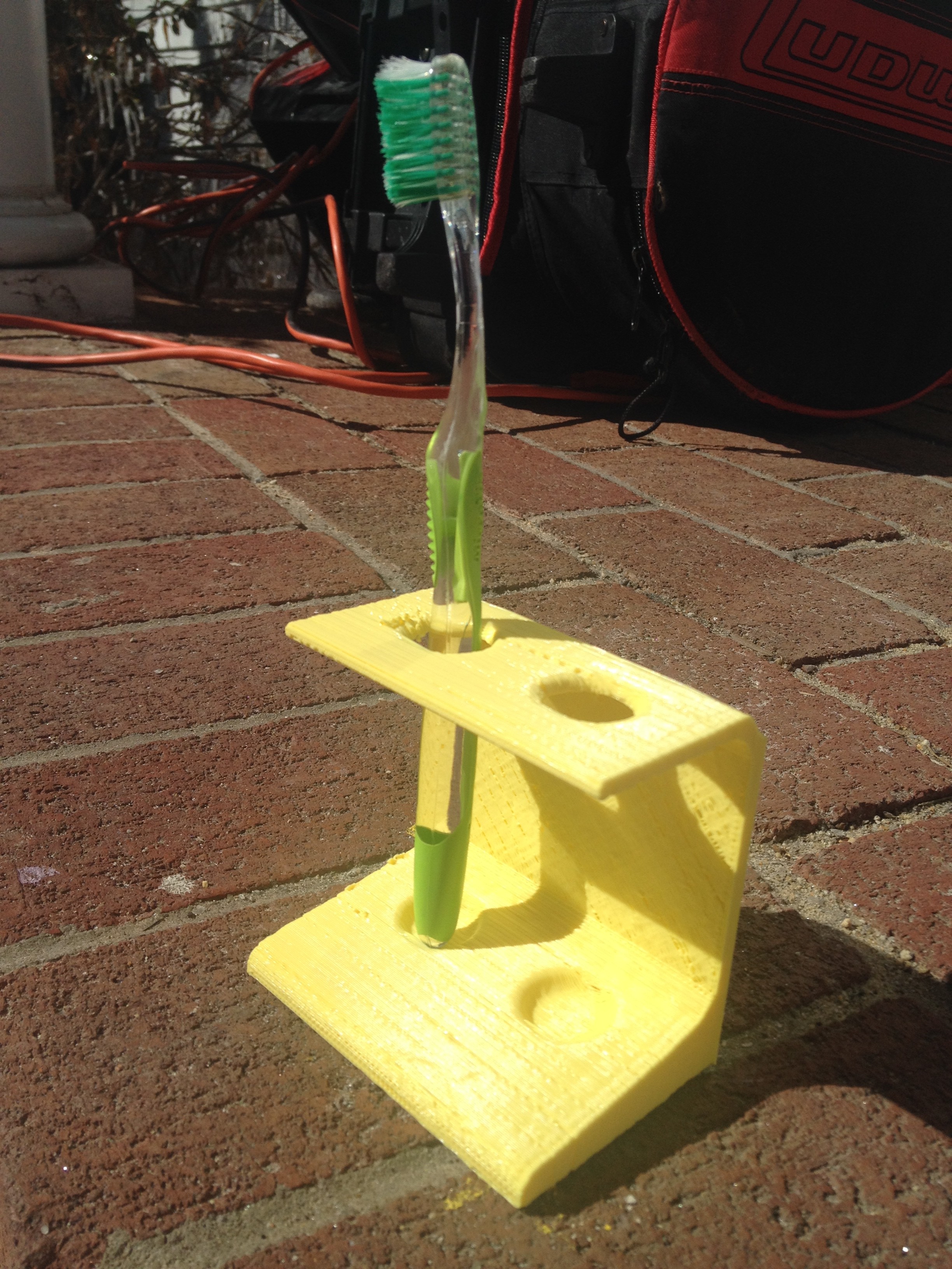
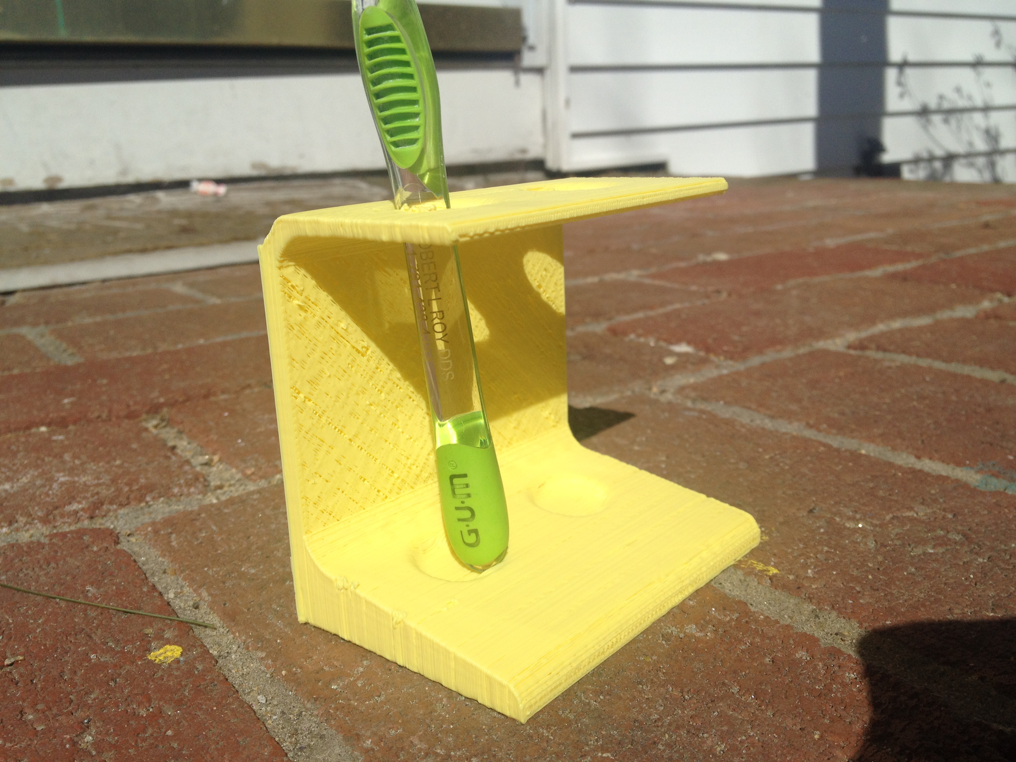
Tooth Brush Stand – February 28, 2014
And now, the thing I’ve used most in the past year since that February full of 3D prints.. I use this thing every day: a Tooth Brush Stand:
Must-watch video to end the month:
That’s it!
It was good having a schedule. It was good motivation to bring my RepRap up from the basement. It was a lot of fun. I highly recommend trying this yourself.
Sadly, it’s February 11th 2015 as I type this, so it’s safe to say I’m not doing #FFo3DP THIS year in 2015 like I did in 2014.. Maybe I’ll do it every other year. But give it a try, post your pictures, and tag them all #FFo3DP! 🙂
More of my RepRap blog! I’d love to at least catch up to covering last year’s Makerfaire (Makerfaire NY 2013) before this year’s Makerfaire, which is at the end of this week (on September 20 & 21, 2014). That won’t be this post, but the more I post, the closer we get.
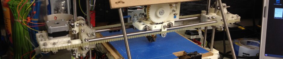
Having just given the Museum of Science the RepRap I made for them in the last post, I was now free to work on my 2nd RepRap for myself (the same model – a Prusa IT2, to go along with my first original (Sell’s) Mendel). Luckily I’d started it before the handoff, so it was easier to get working on it.
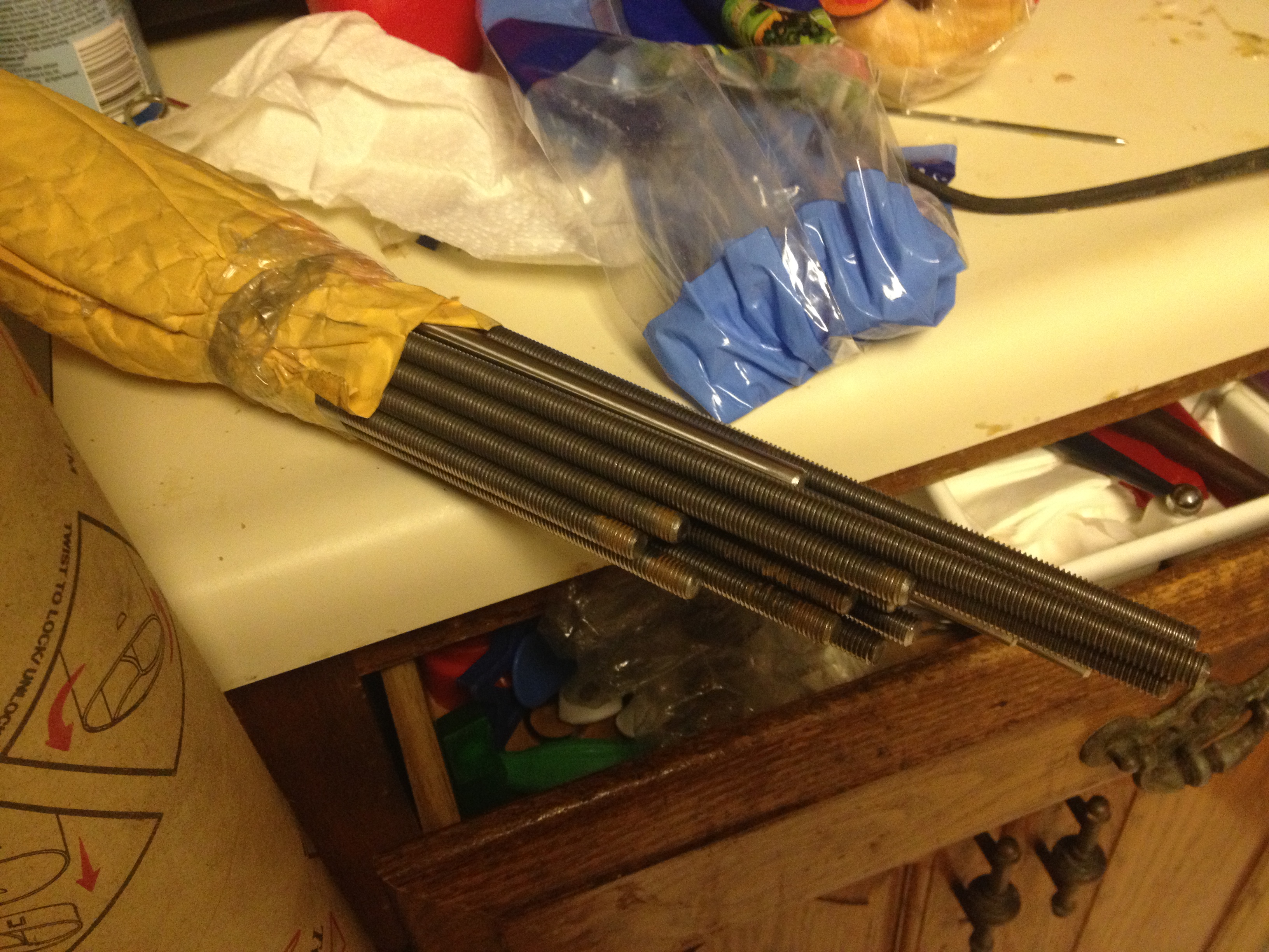
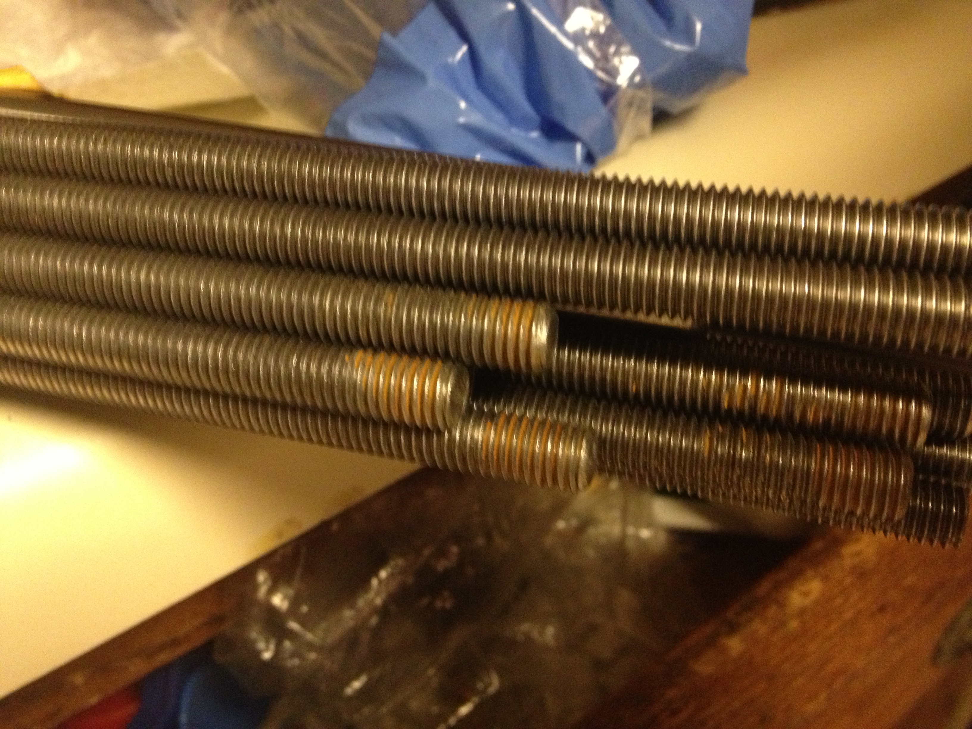
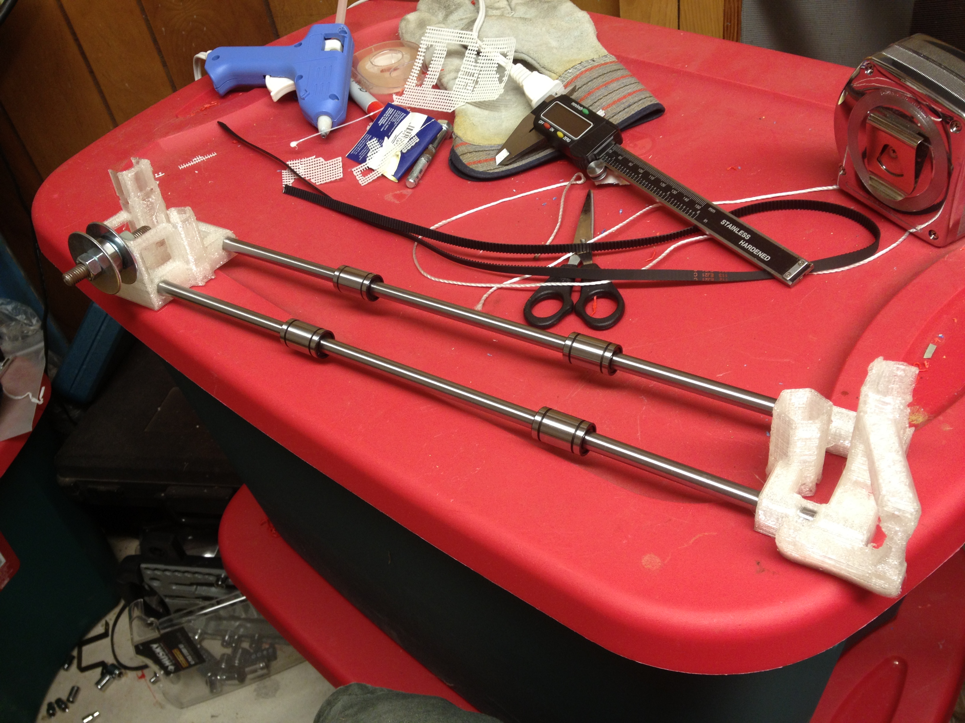
I found another picture of cut and ground rods, although to be honest I can’t remember whose those are.
They look slightly rusted, which I’m confused by because at this point I had my grinder and would have cleaned them off. They’re not for my RepRap since its frame was already built. Maybe Joe Werther’s? Too many RepRaps – I’m losing track. 🙂
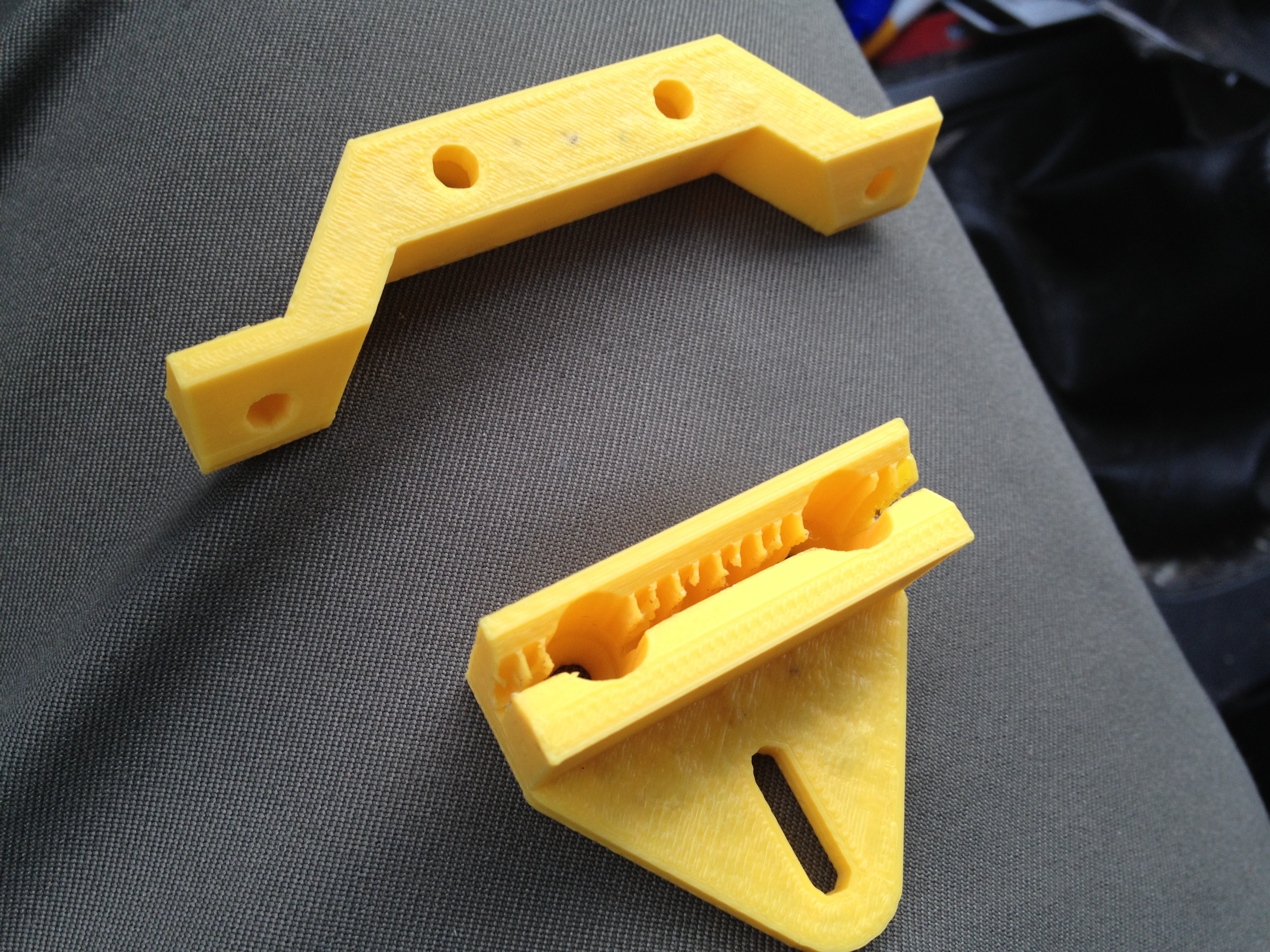
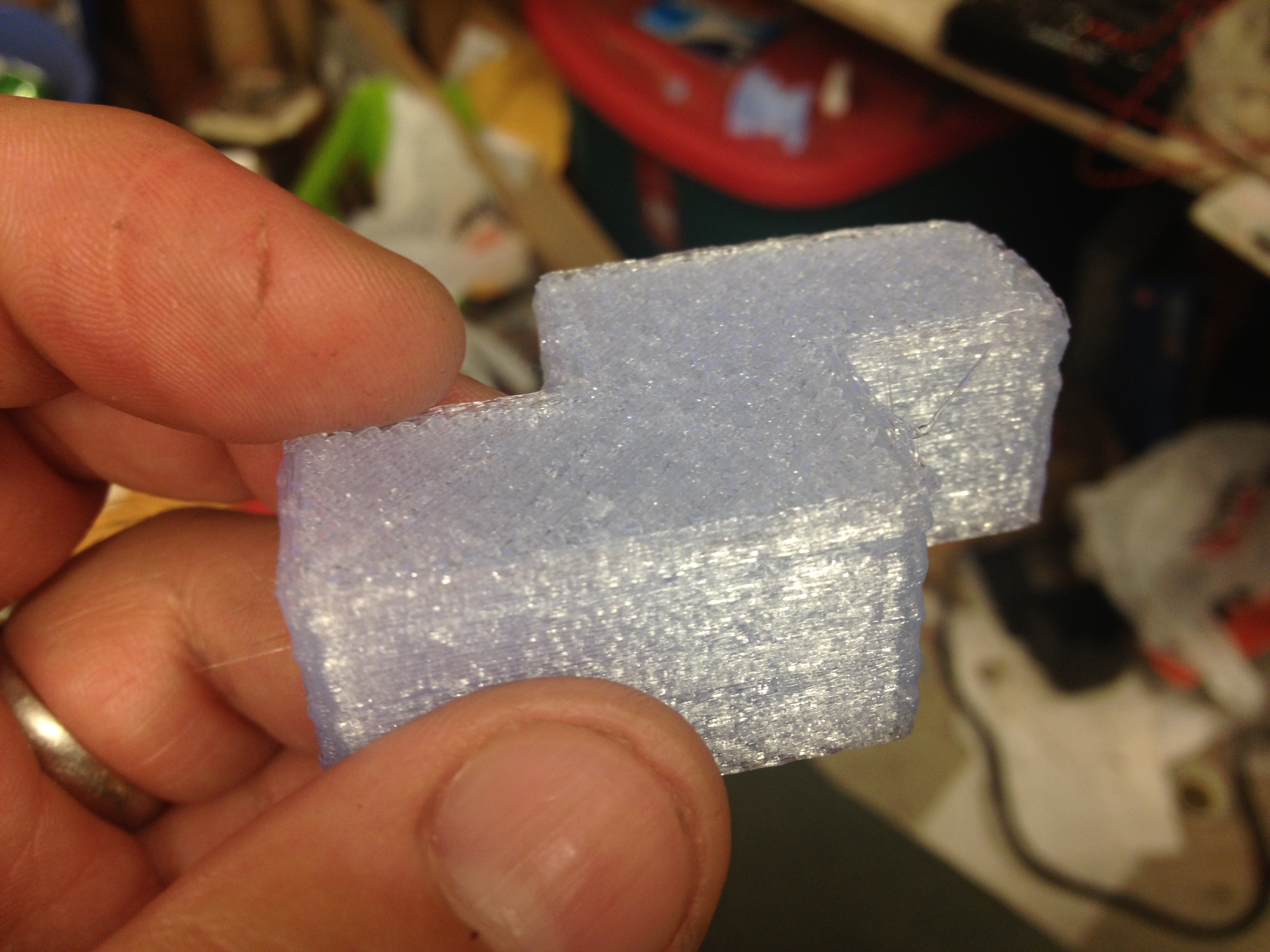
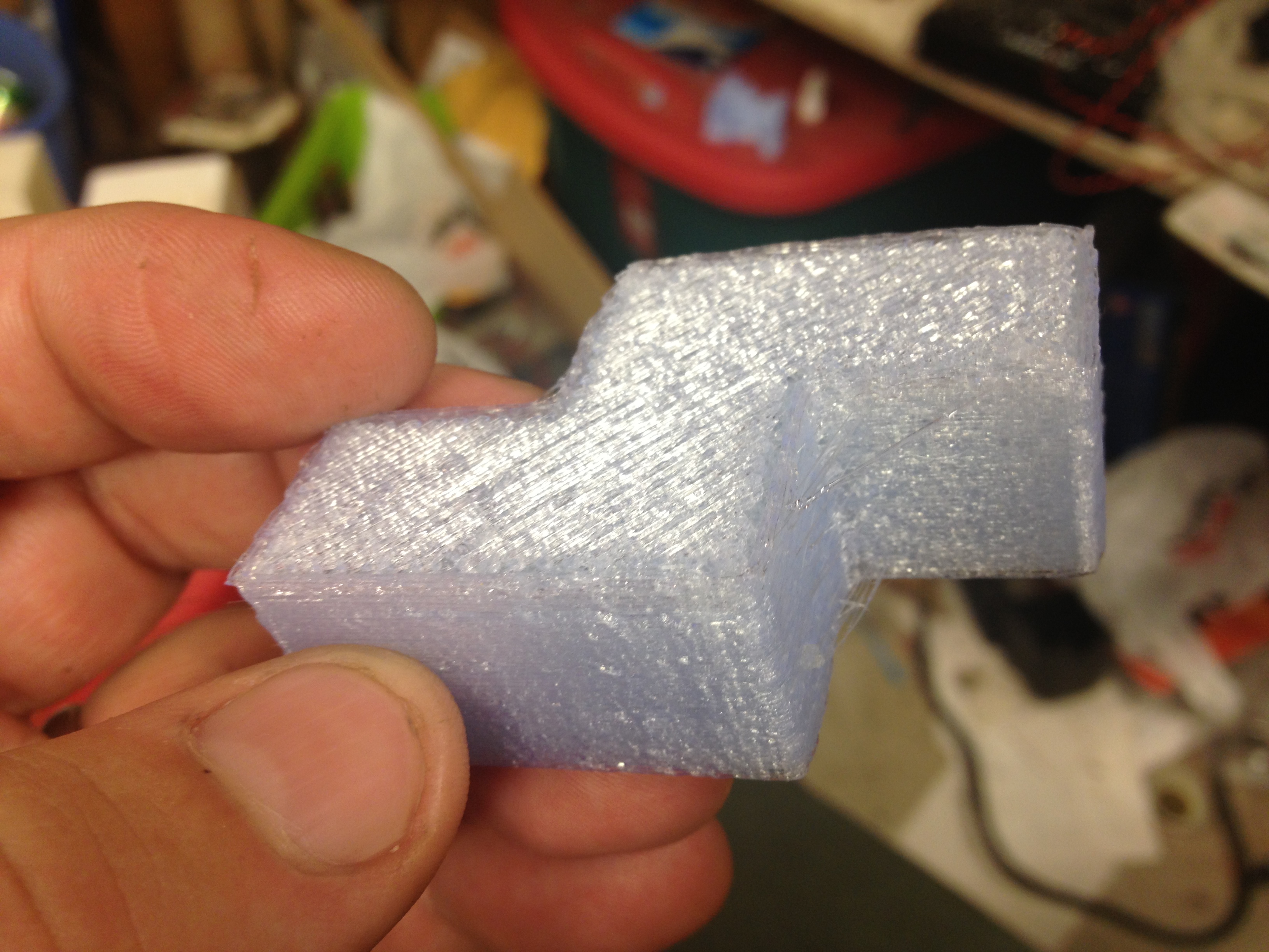
I had tried designing a version of the OpenX carriage for the Prusa IT2 since I liked removing the carriage easily. I printed these out, but I don’t think I ever used them:
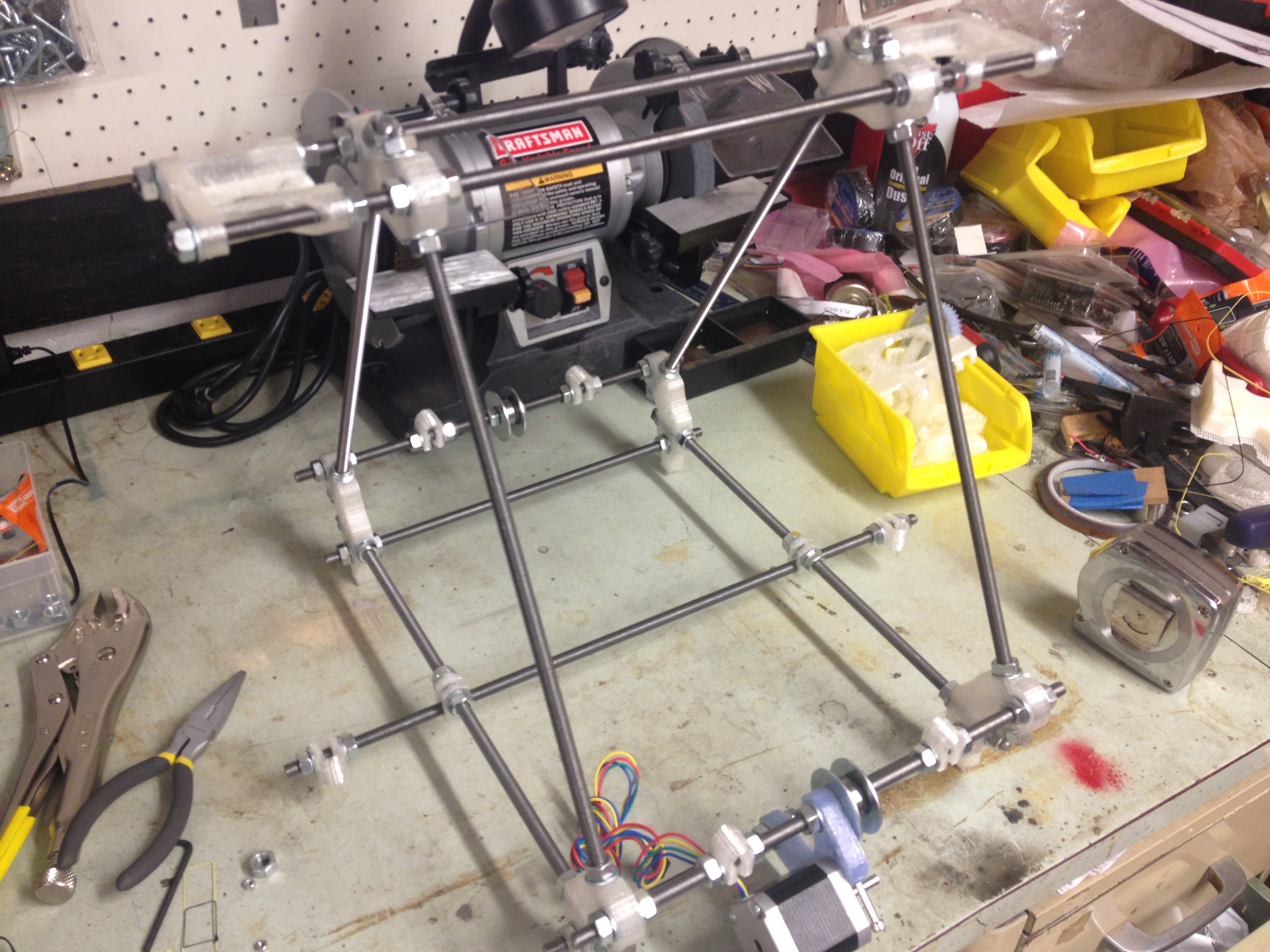
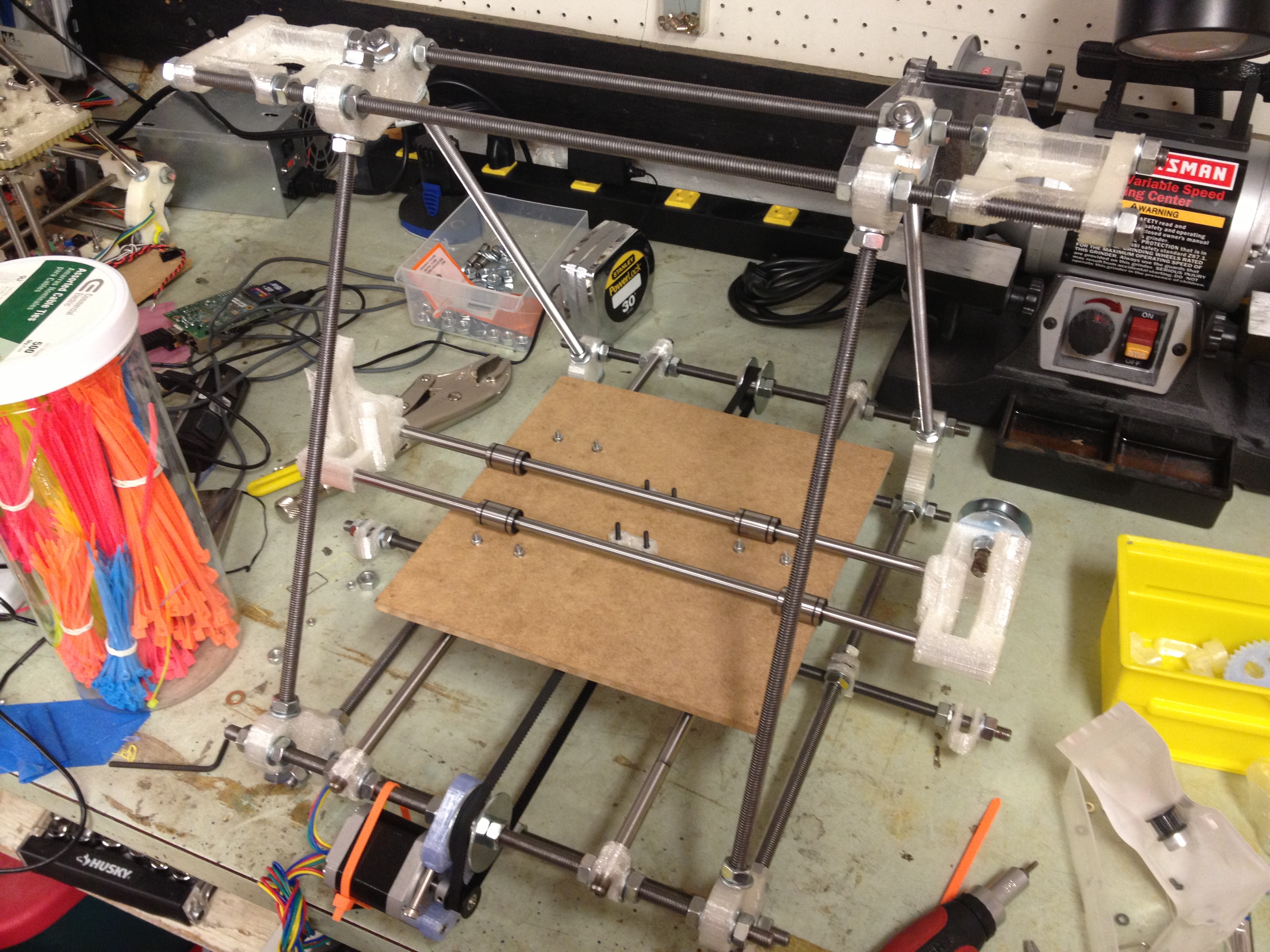
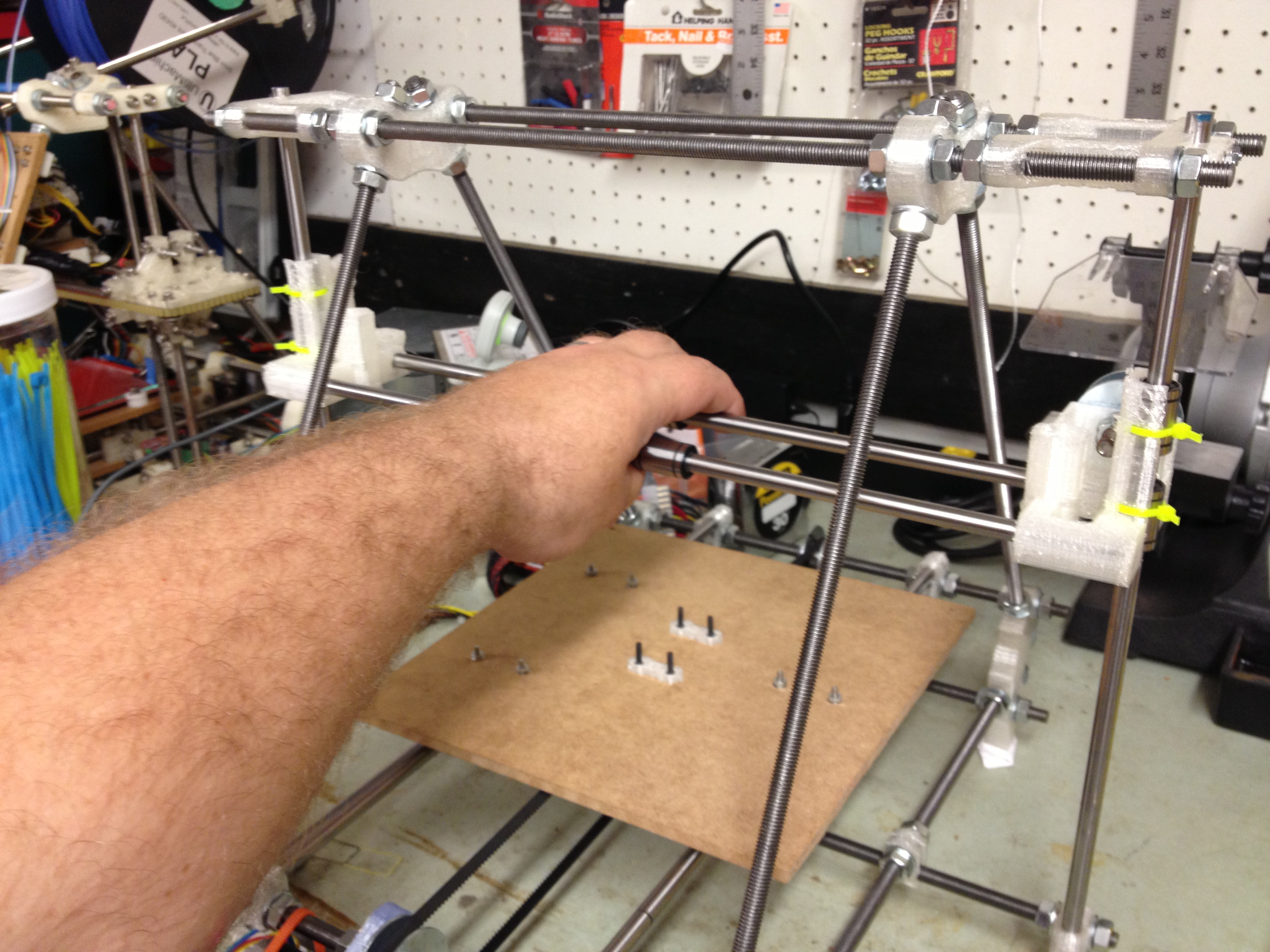
Anyway, continuing my frame assembly, I added the bottom rod and top rods, with the z-motor-mounts and bar clamps.
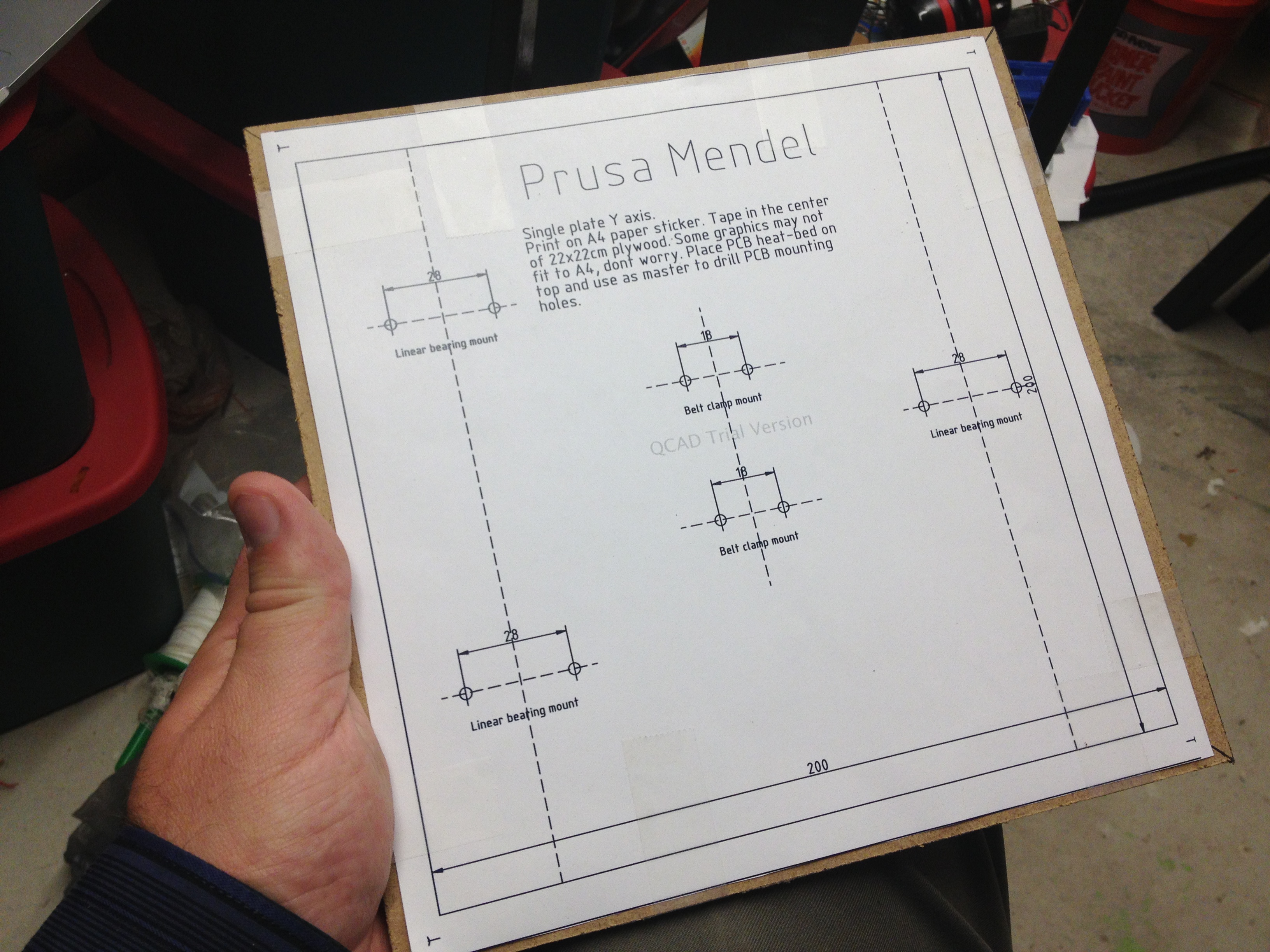
It was time for the bed..
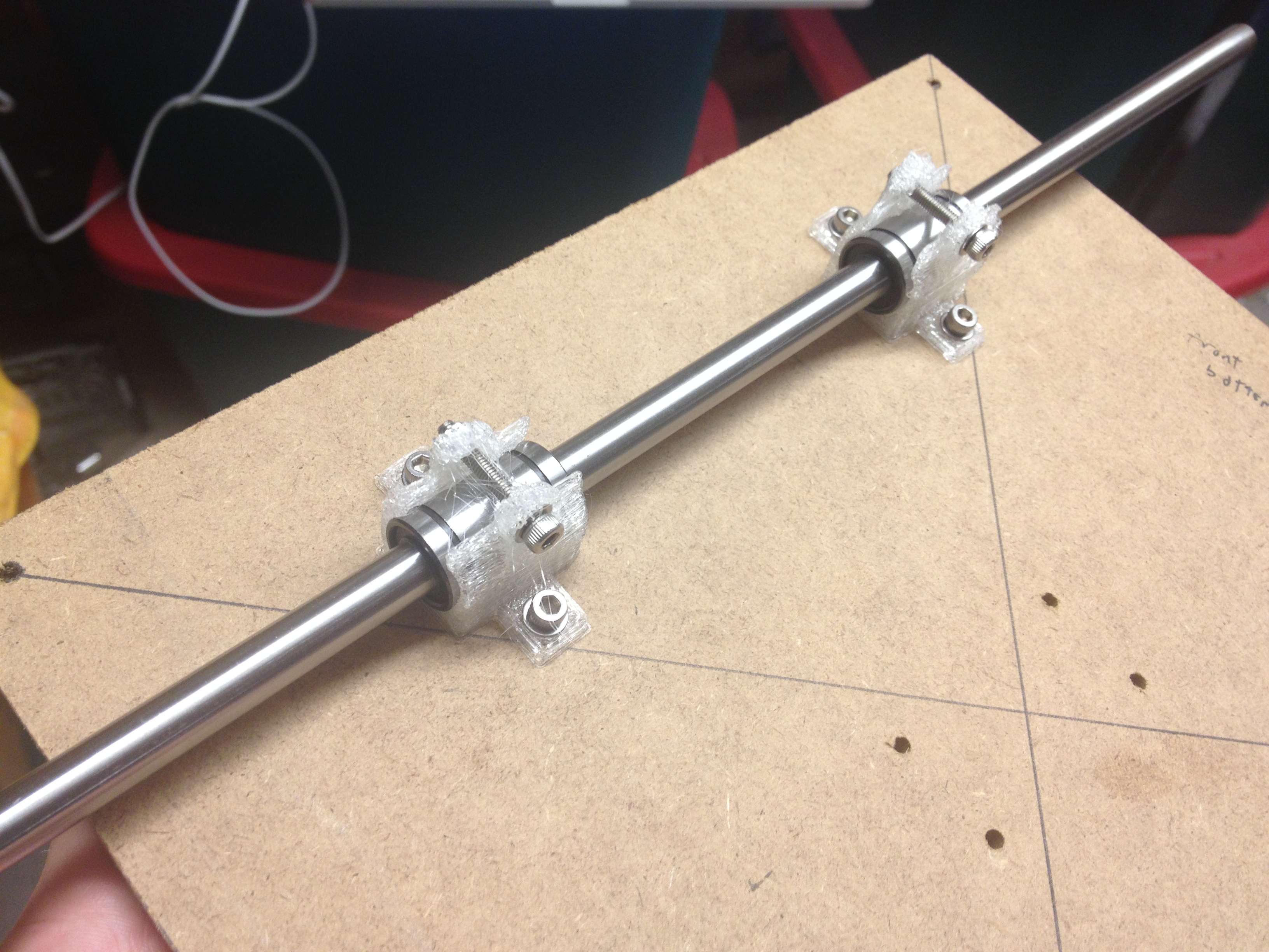
Here was a note I made to myself about how to attach the LM8UU holders beneath the bed:
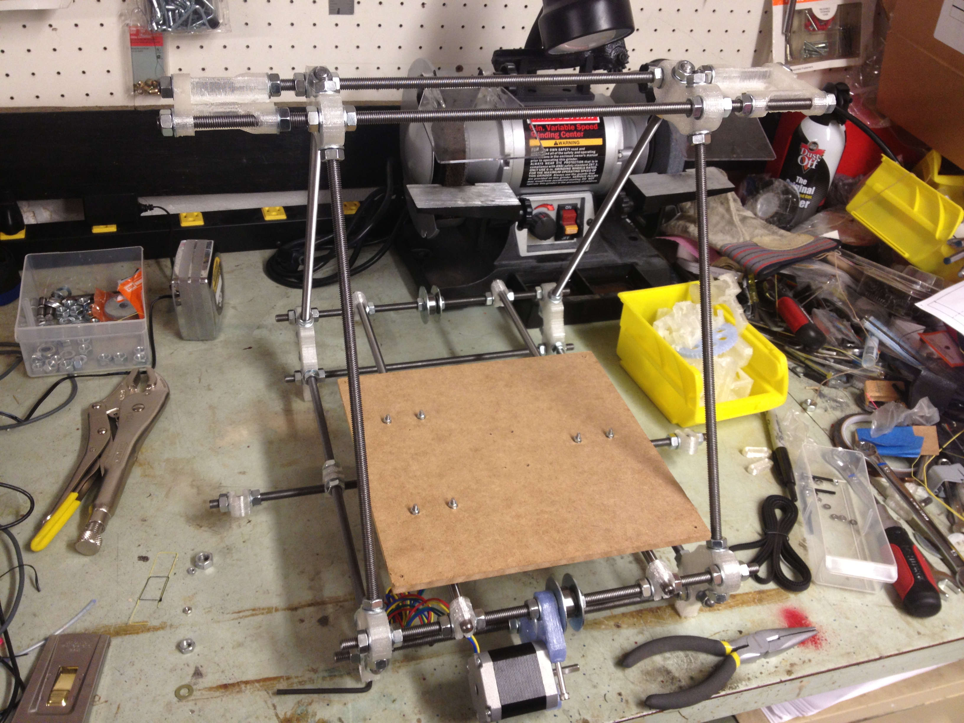
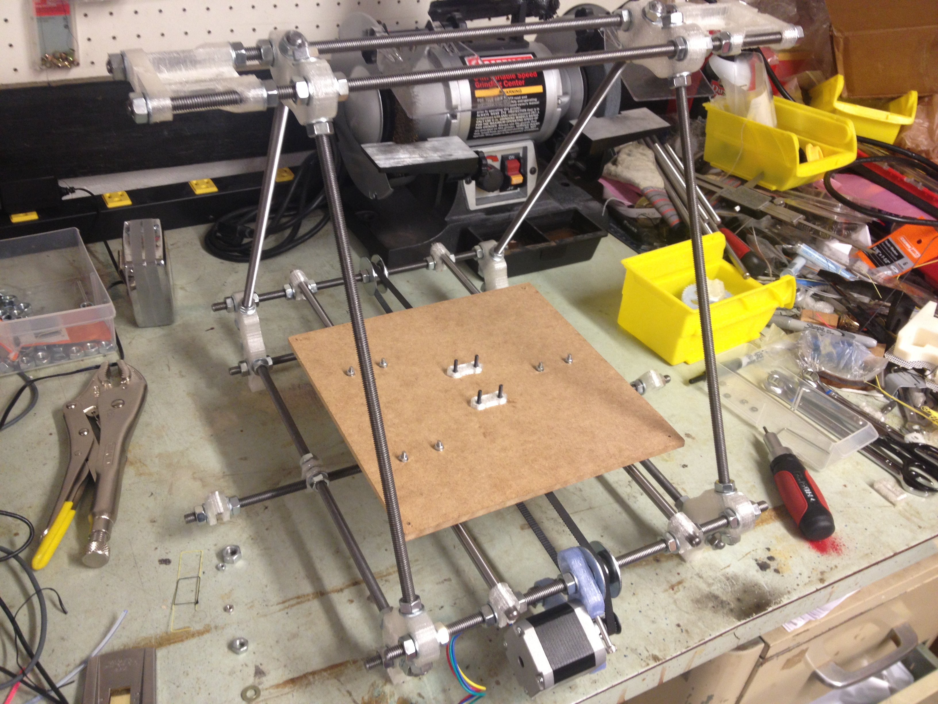
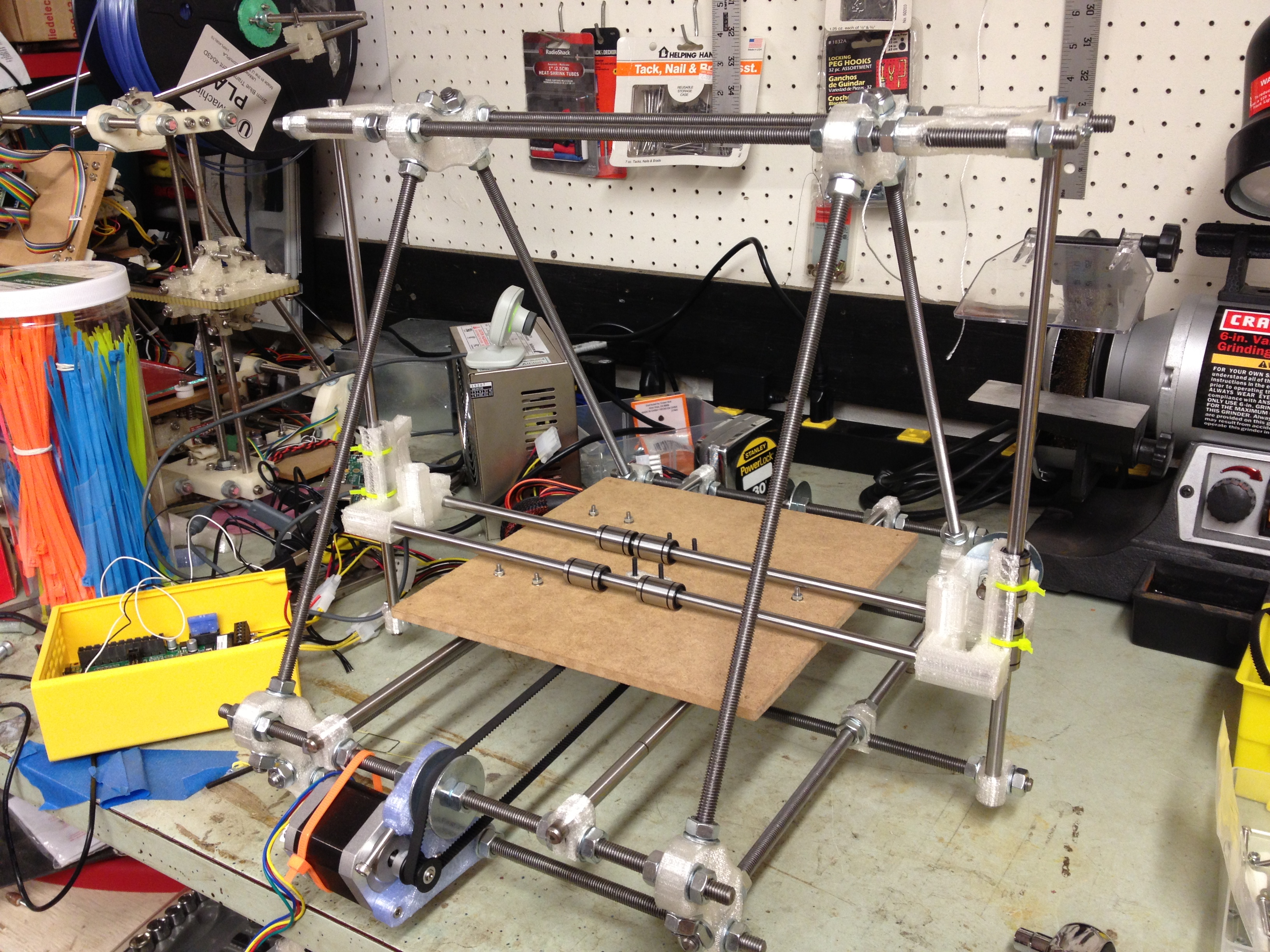
Here is the bed mounted on the frame:
…and here is a video showing just how smooth it glides.. oooooh..
…and another showing the same from the bottom:
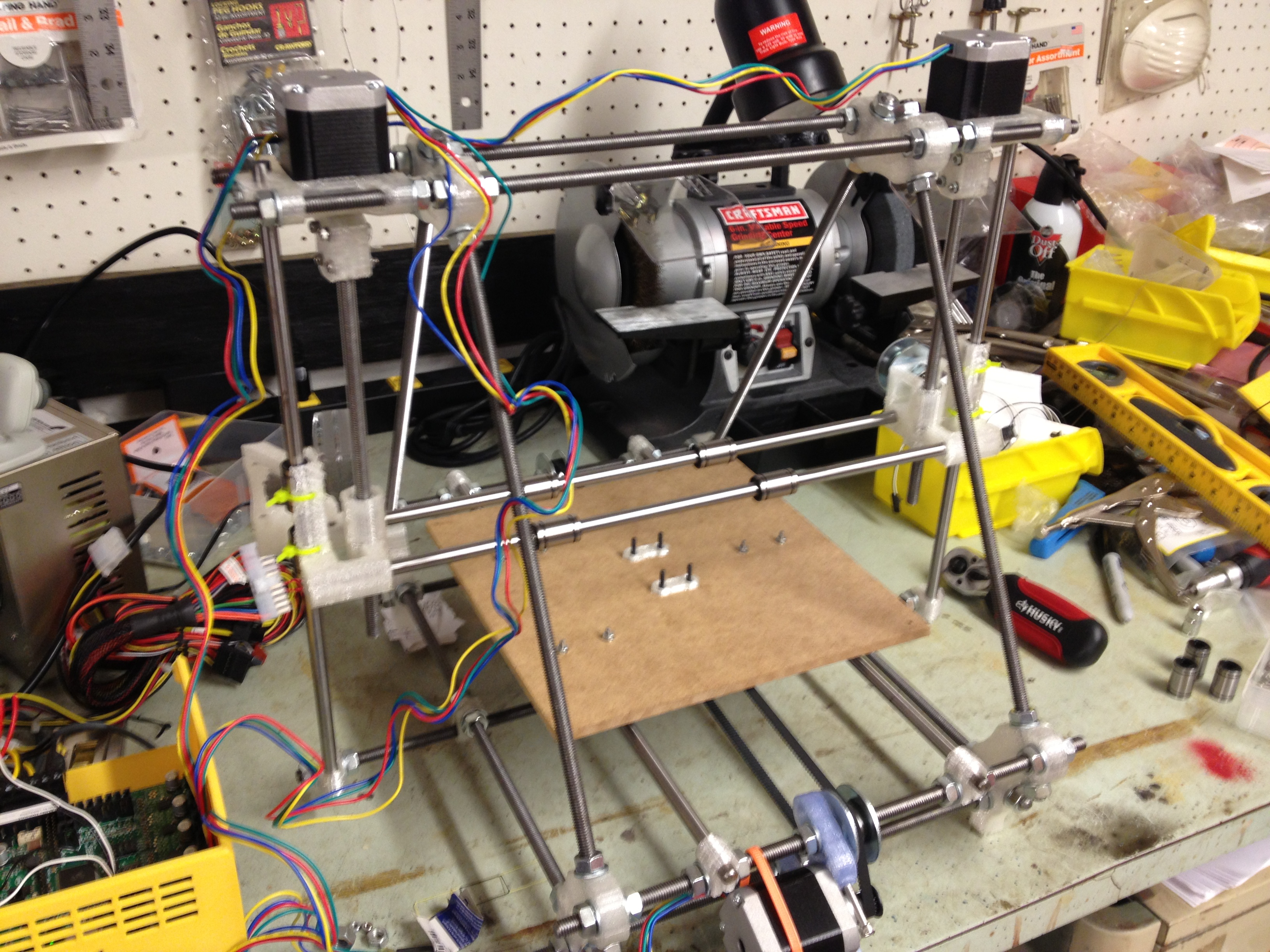
Then I added the y-axis motor and belt.
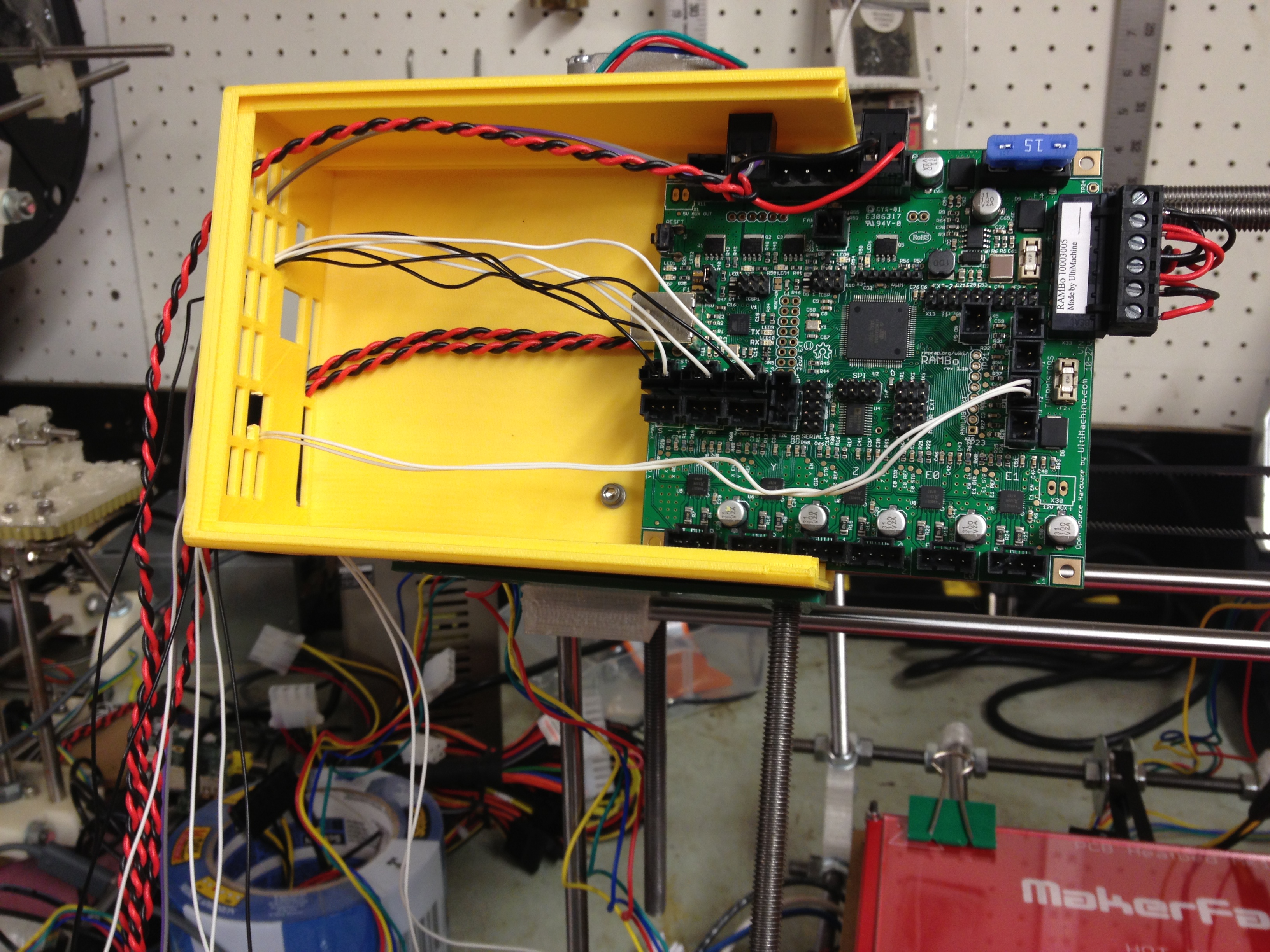
To test it, I’d need the electronics set up. A year ago (from that point) at Makerfaire 2012, I’d seen Johnny Russell selling the RAMBo board (RAMPS but all in one board), and I’d decided to go with that for my 2nd RepRap. (I had an earlier version than the one I just linked to).
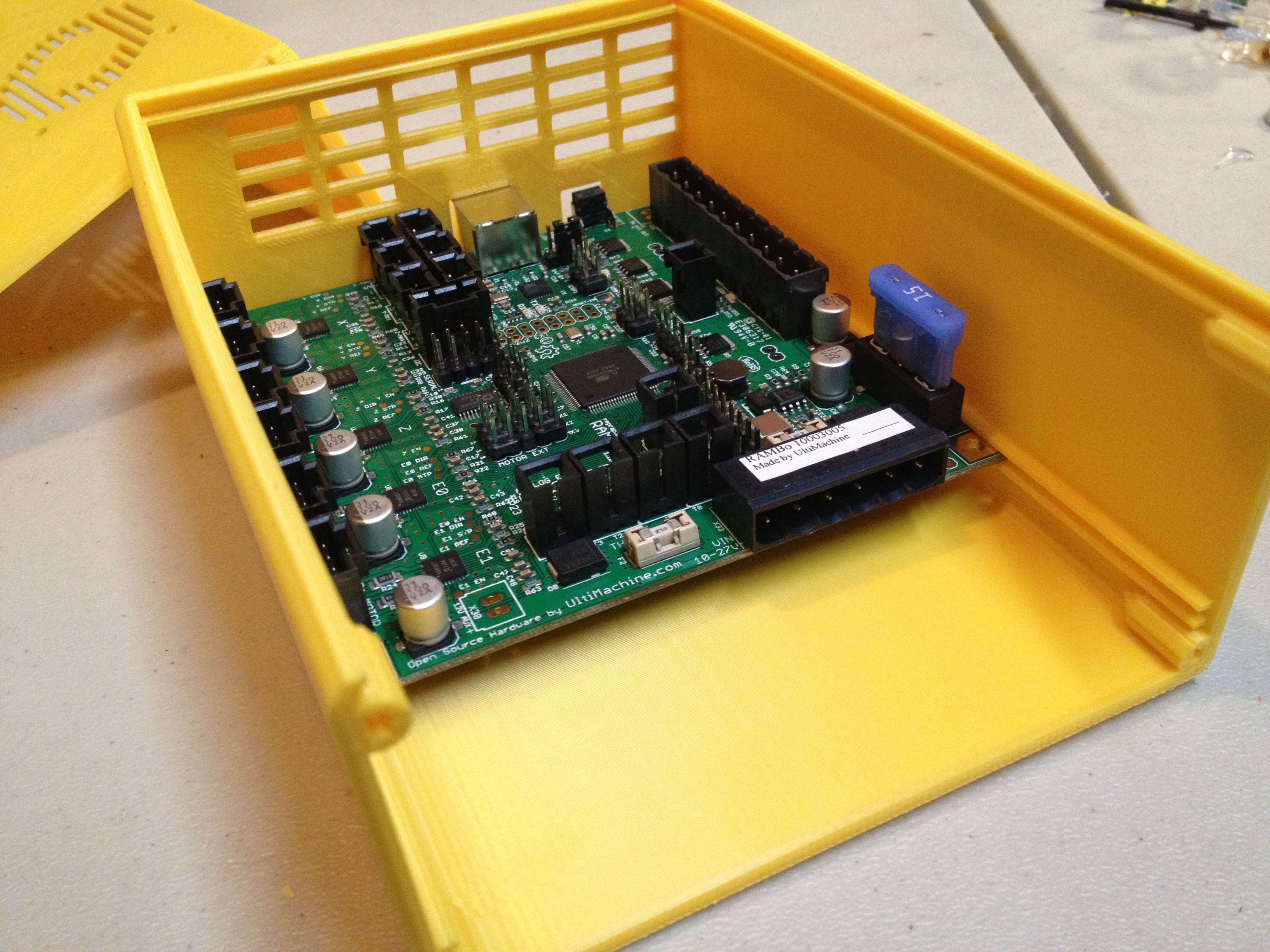
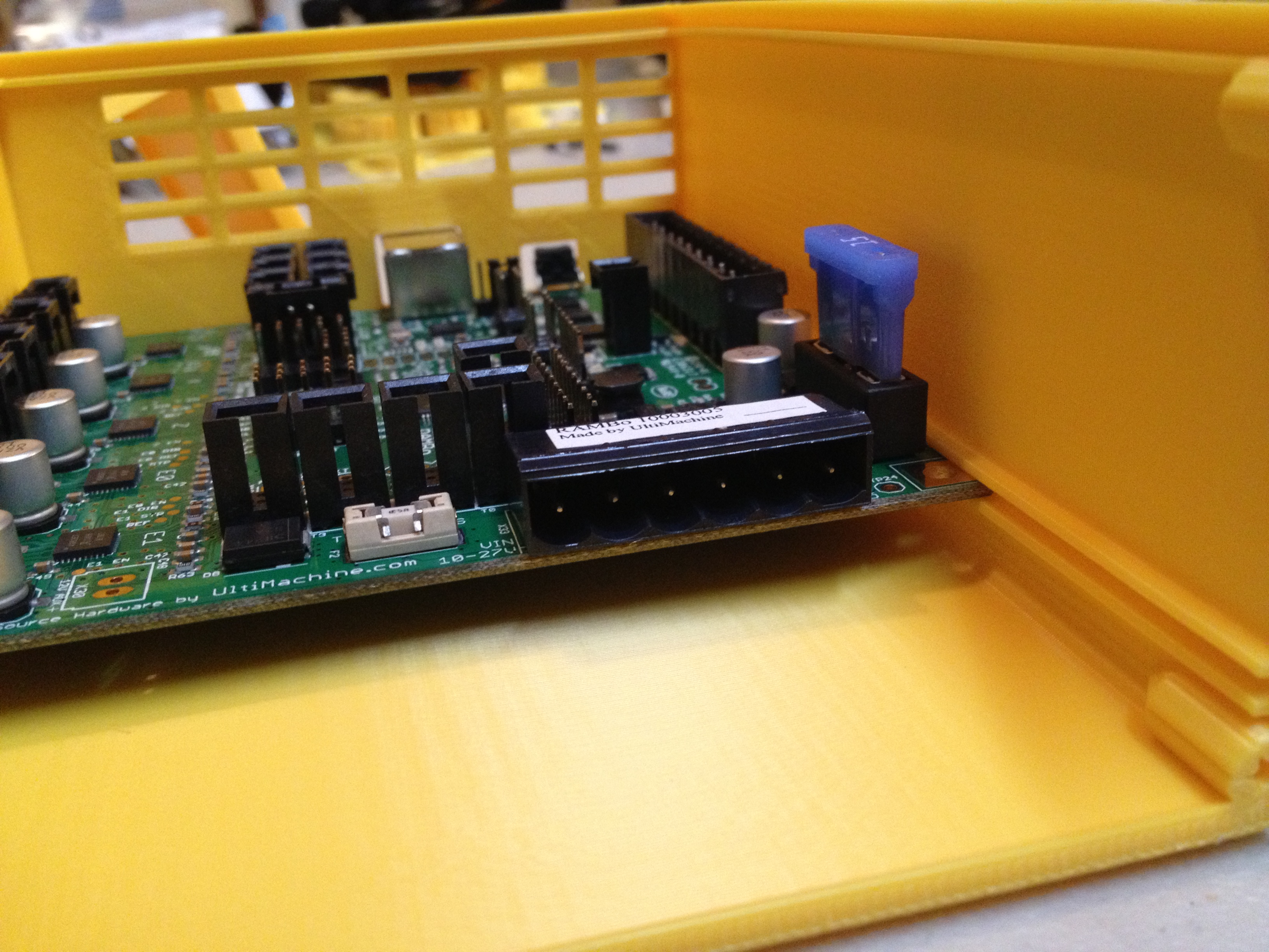
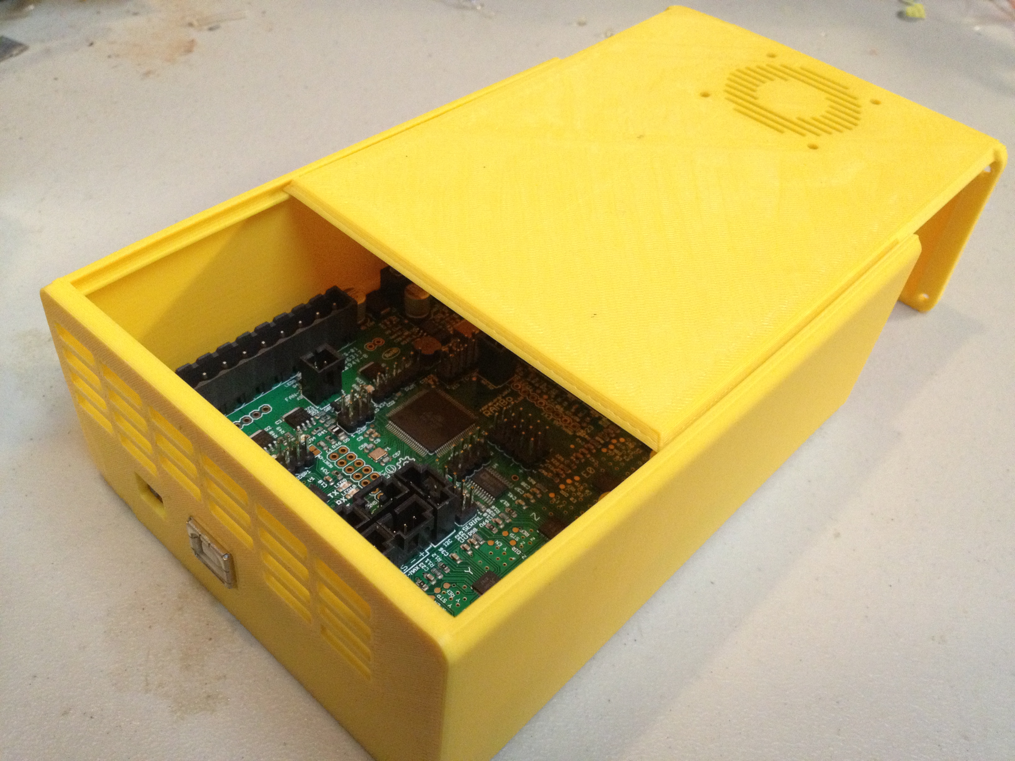
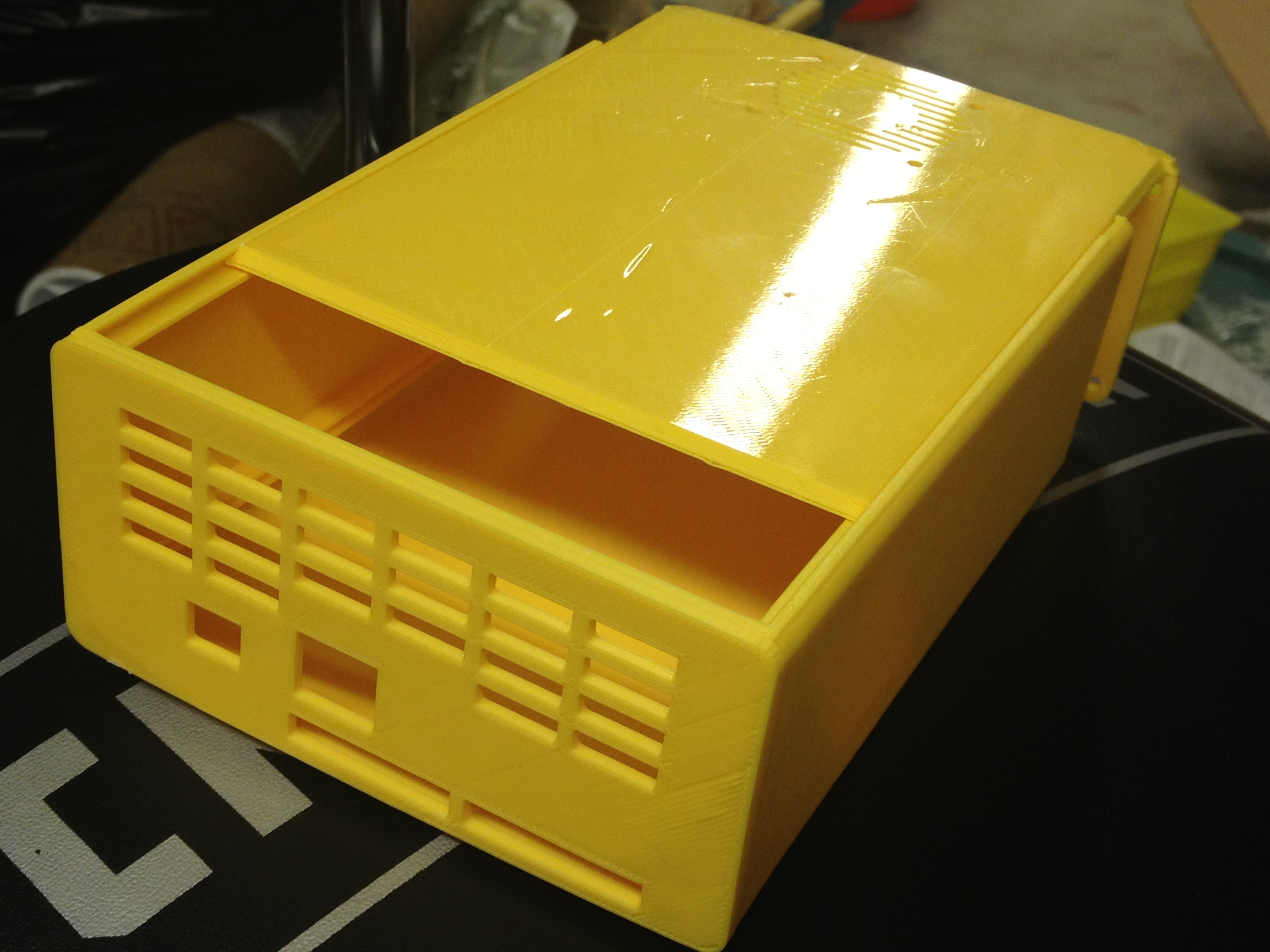
For the Museum of Science’s RepRap I’d printed out this Sliding Lid RAMPS 1.4 box to hold the RAMPS and Arduino Mega board I’d used. I liked that and wanted it for RAMBo, so I designed my own, derived from that one.
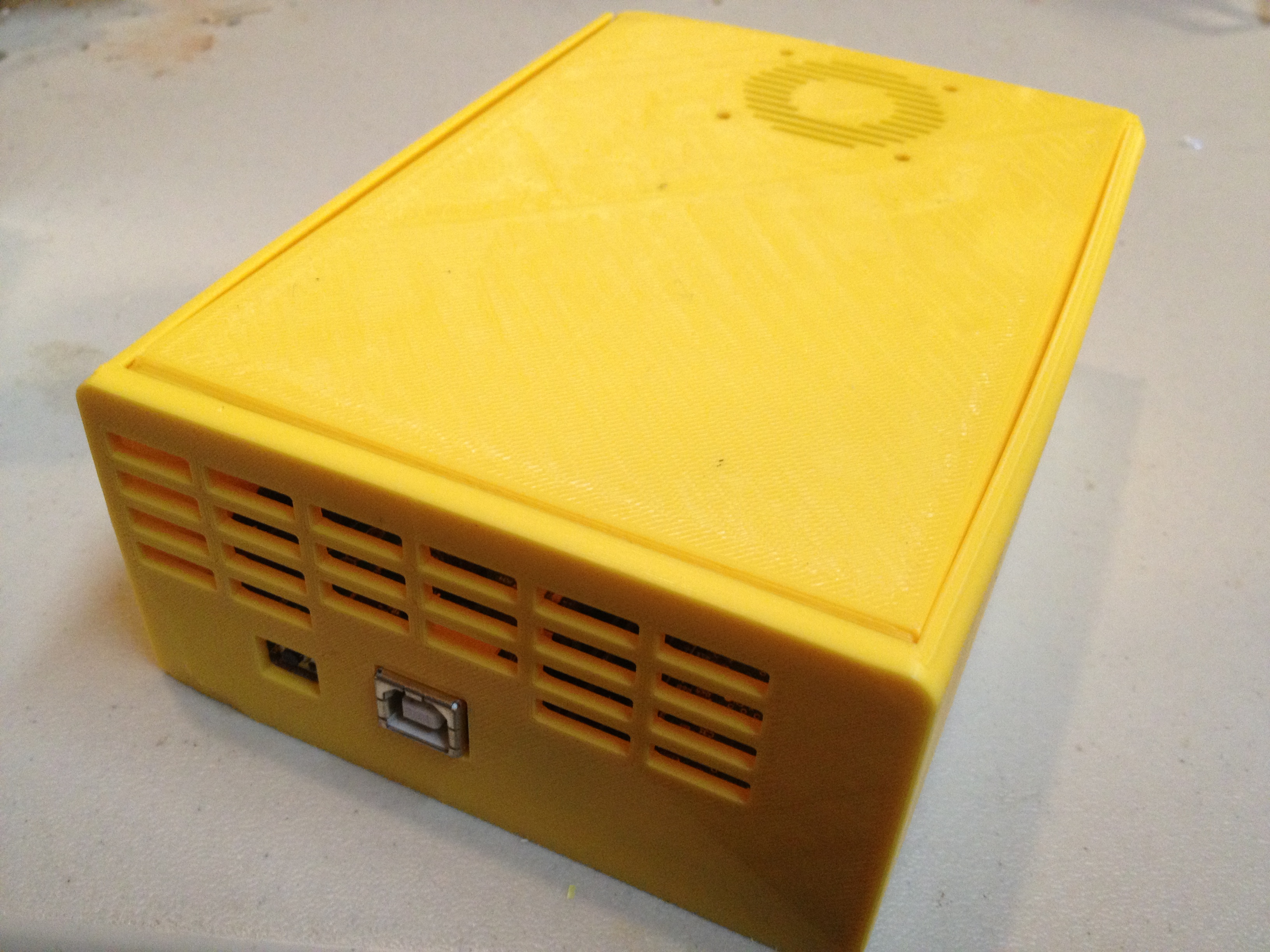
A few prints later and it was done. It’s on thingiverse.com now: RAMBo Box
For the time being I left the RAMBo Box to the side, but wired up. Now I could finally test my Y axis!
Then I made it a little faster..
…then a little faster than that..
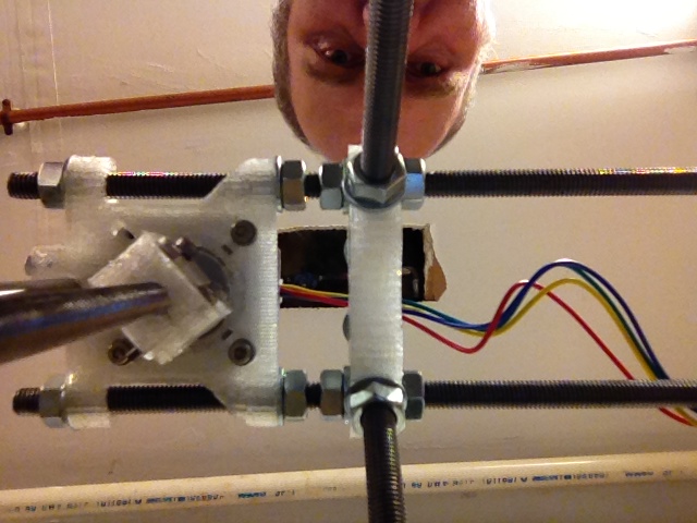
I assembled part of my X-axis next.
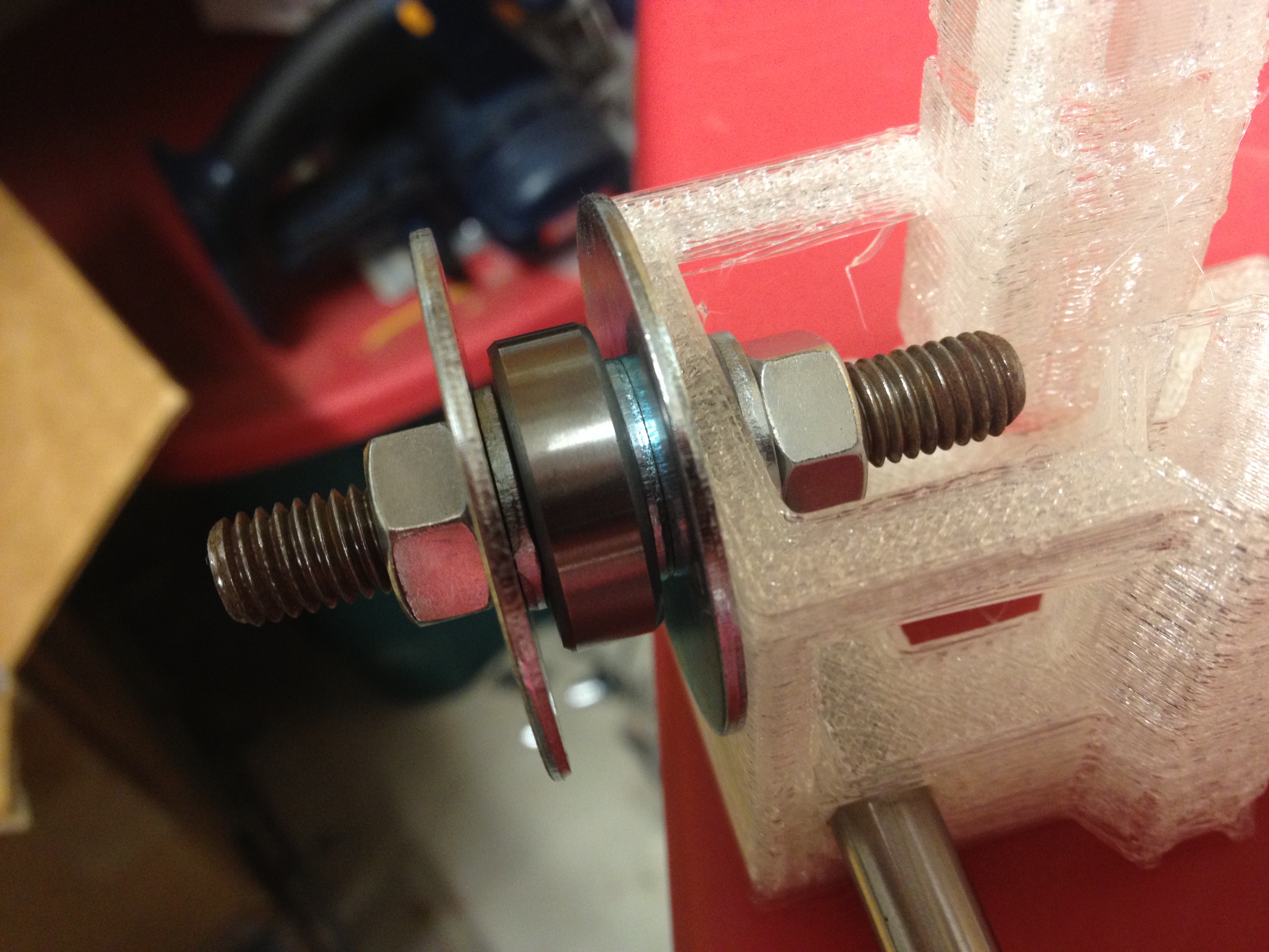
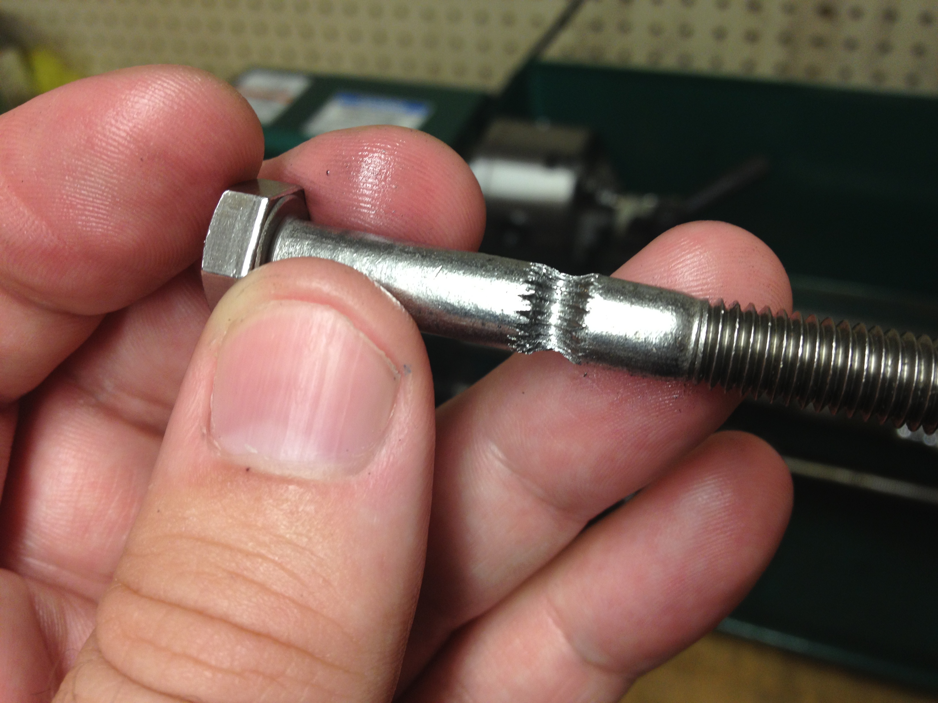
So now it was time to line up the X-axis, and adjust the Z-axis motor mounts on the top bars (again, remember that I did the modification of adding an extra nut between the frame vertex and the z-motor-mount so I can adjust it.. I had to use slightly longer smooth rods for the X-axis to do that).
I did the same thing I’d talked about in previous posts for the MoS RepRap, but this time I just used two M8 nuts for plumbs instead of some bulky purchased one. They worked better anyway.
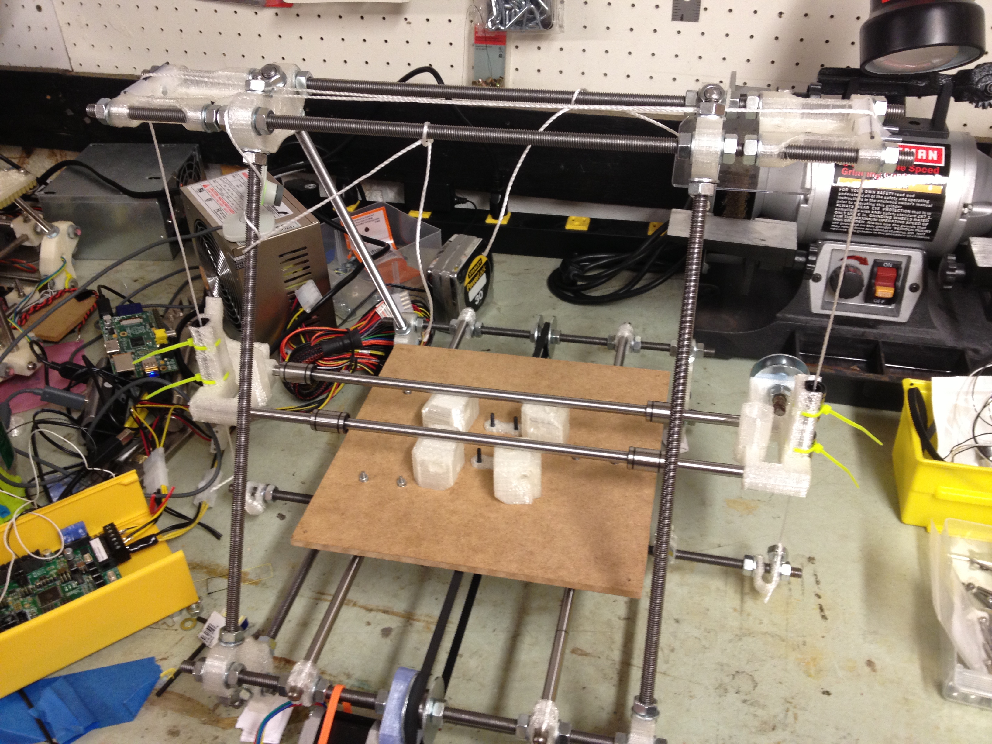
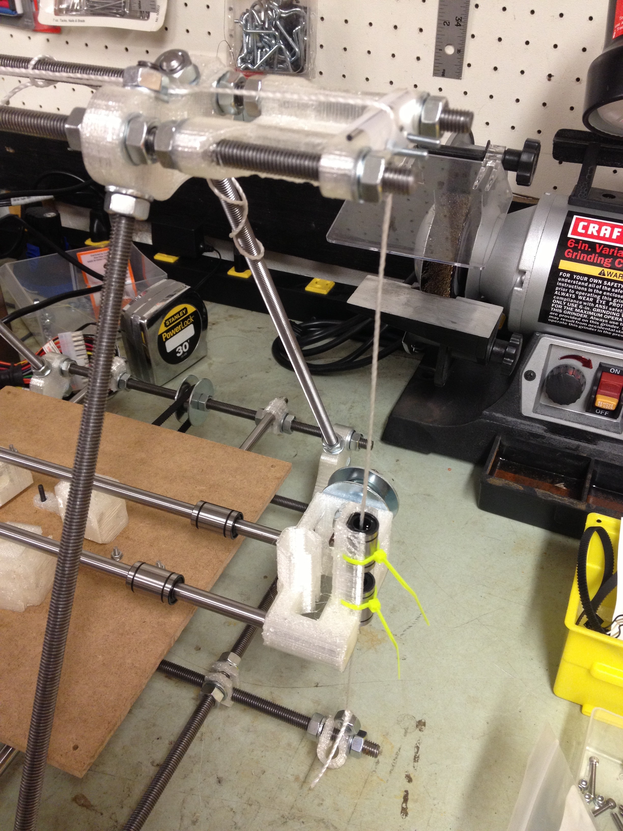
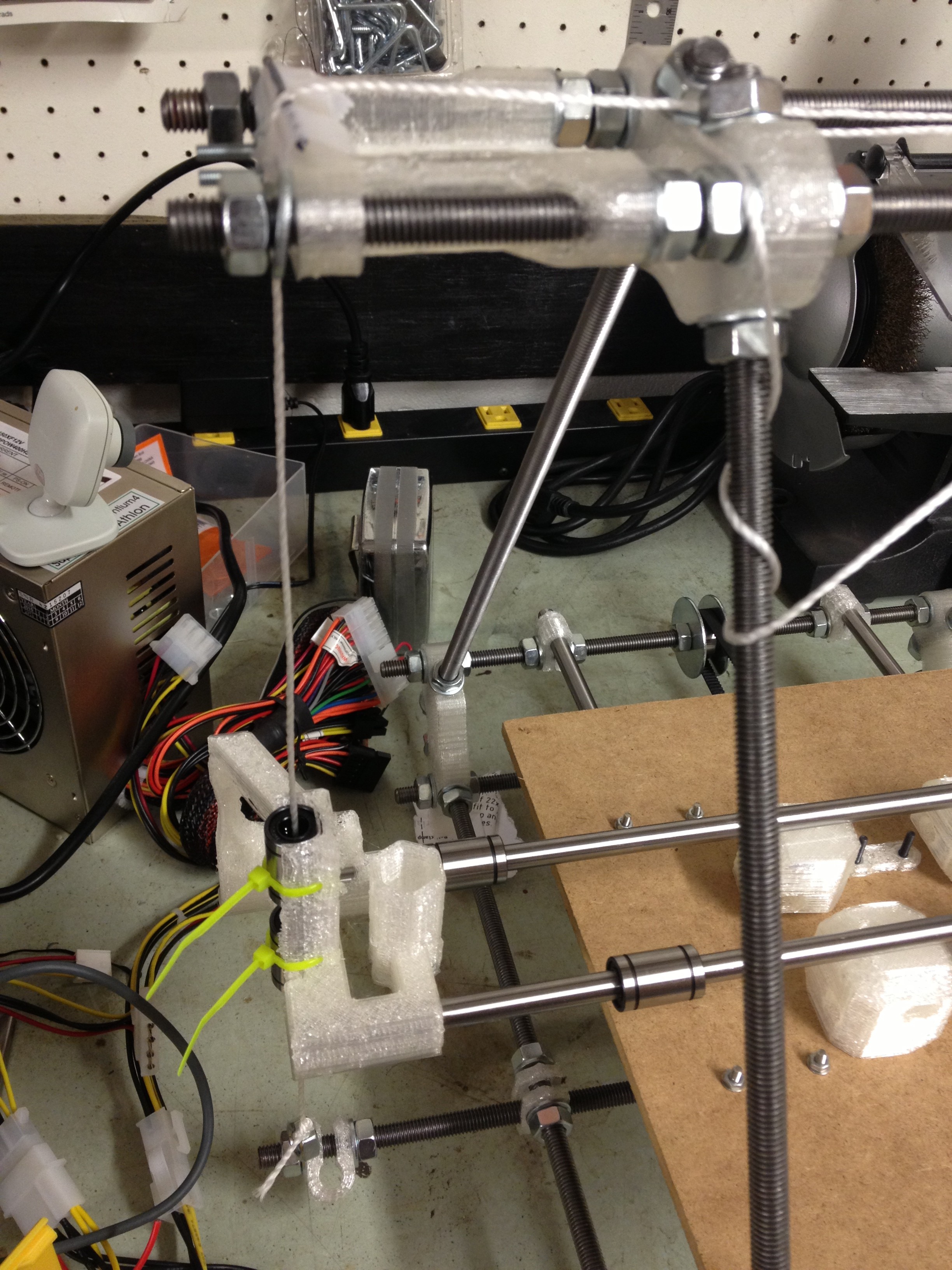
I carefully slid in the smooth Z rods and tightened them, and could then raise the X-axis along the Z-axis by hand.
Then I installed the Z motor mounts and leadscrews. Here is the X-axis being suspended on its own by the leadscrews:
When I first tried moving in Z, I saw some z-wobble, but wasn’t convinced it would affect the x-axis in the end:
That led to this video of my phone lying on the bed shooting up as the Z axis moves up and down.
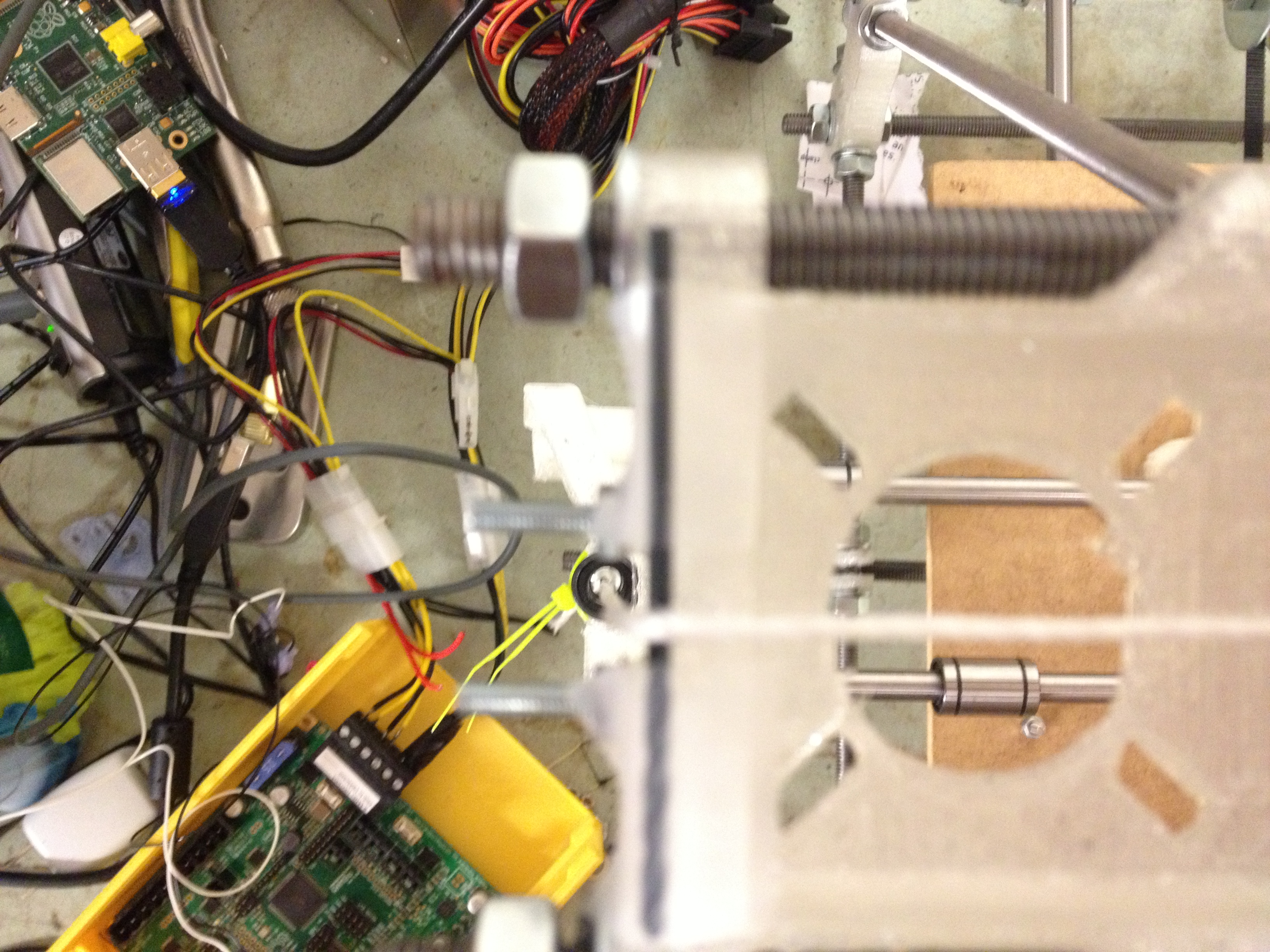
Although I hadn’t run into it with the previous Prusa IT2 I made, I was now having problems with the M8 nuts being too loose in the X-ends, I think:
After fixing the problem with the nuts (I’m not entirely sure how, it was over a year ago, but I imagine I turned off the motors, pushed down to compress the spring, rotated the nut so it fit in the shaft, then released the x-end), I finally had things working. I put on the X-carriage that I’d reluctantly decided to go with instead of the OpenX carriage (which was much better than the previous one I’d used), and made this video demonstrating X, Y, and Z motion!
Woohoo!
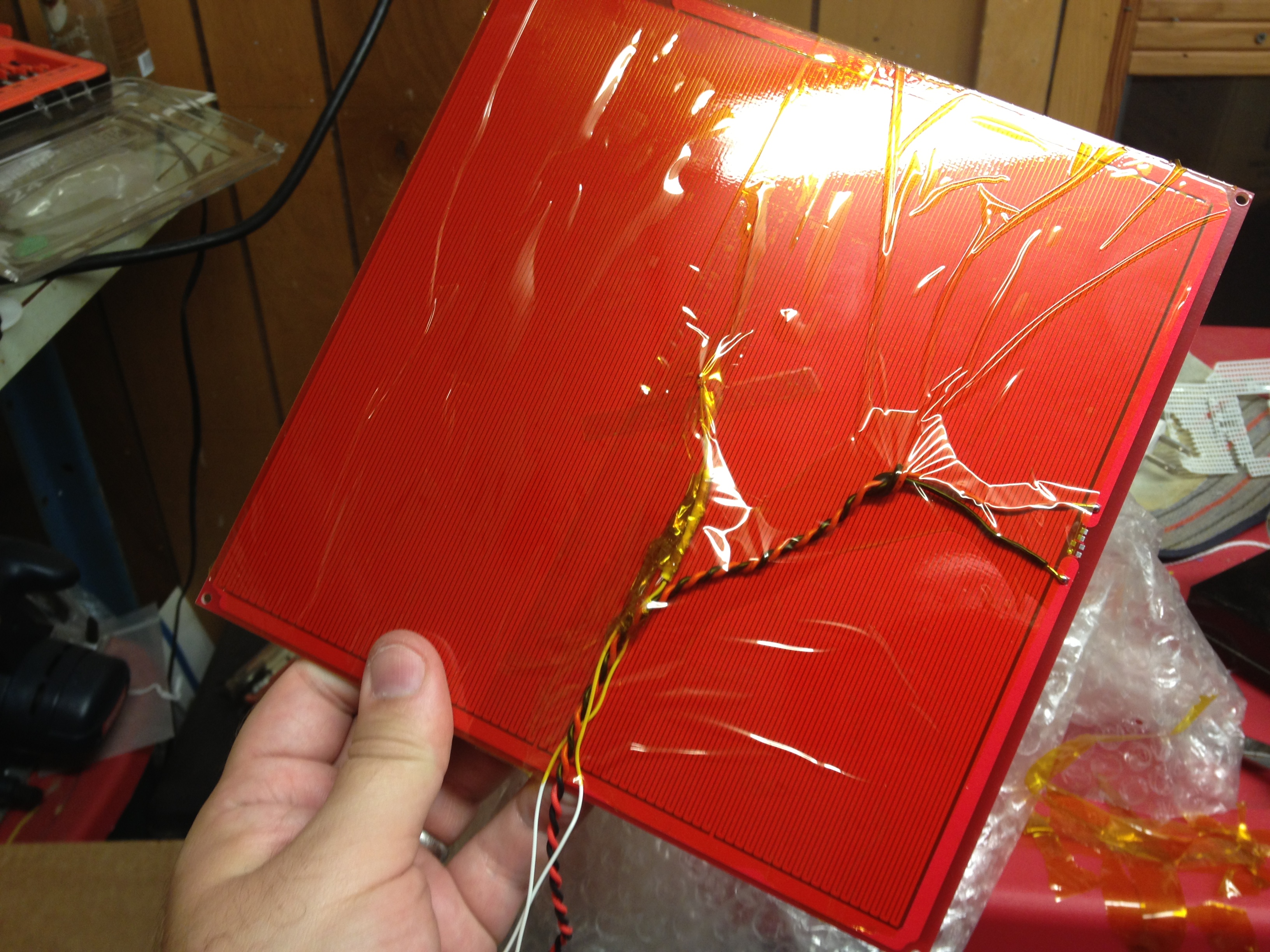
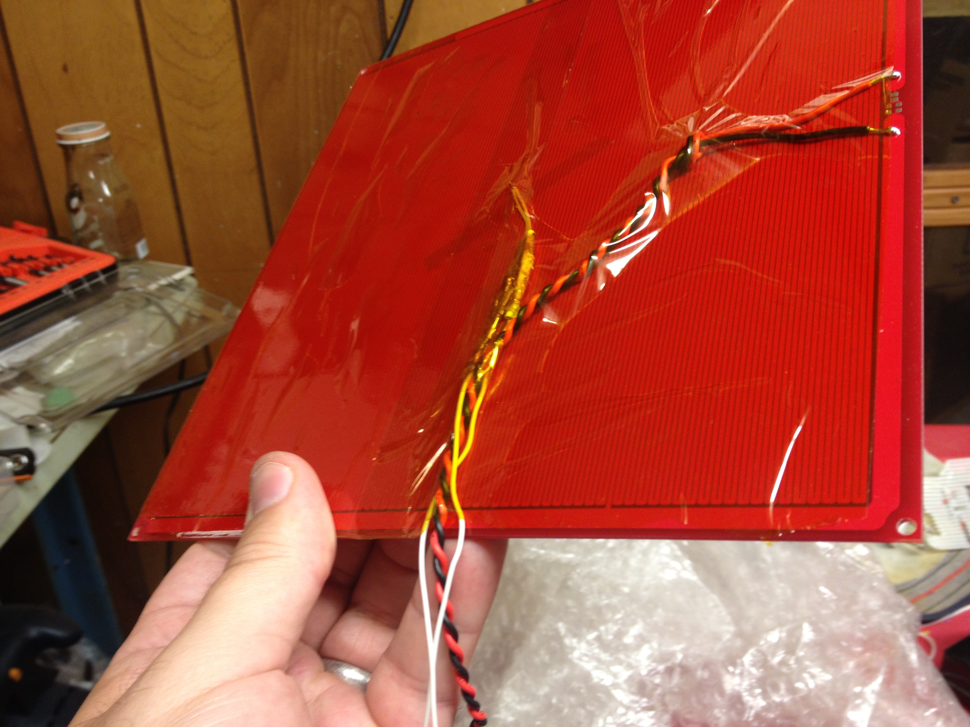
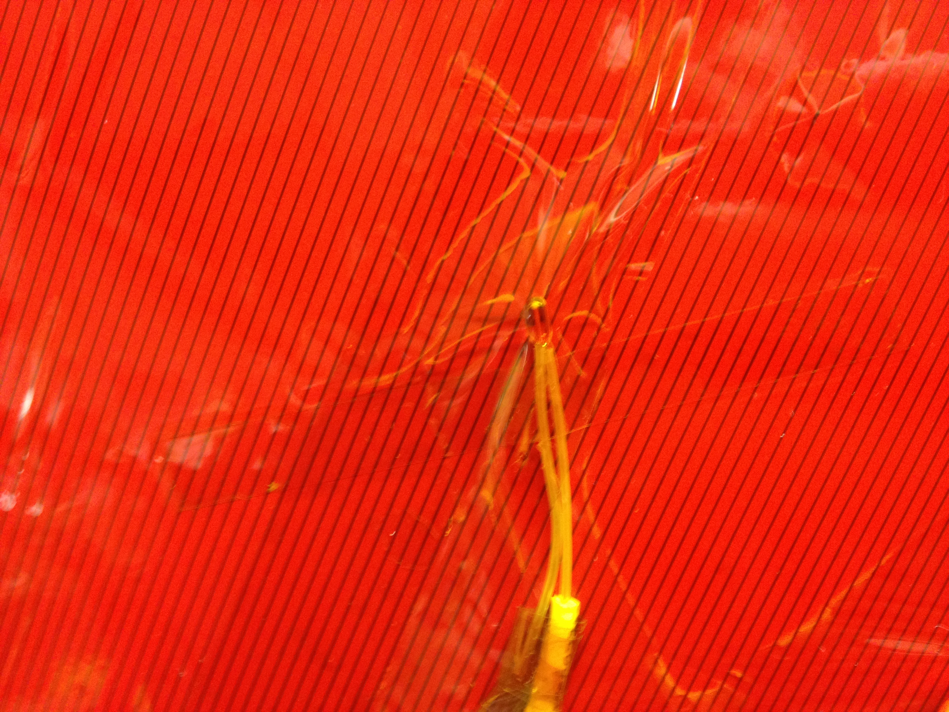
Next, I wired up the heatbed and covered the bottom with a large sheet of kapton tape.
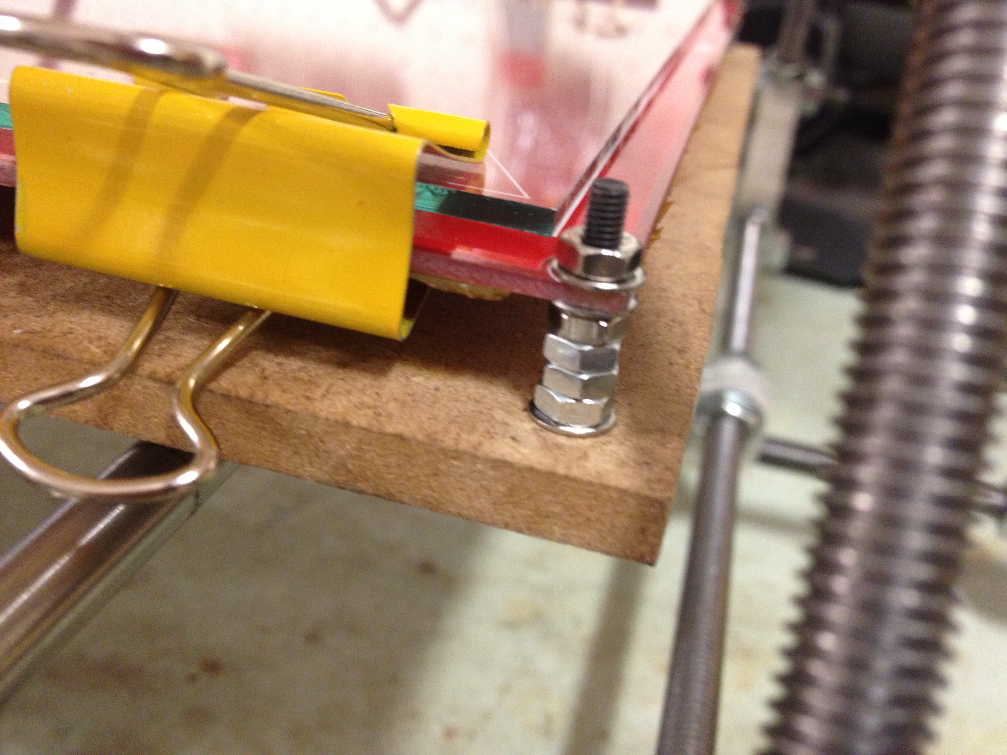
For future reference, I used four nuts for spacing:
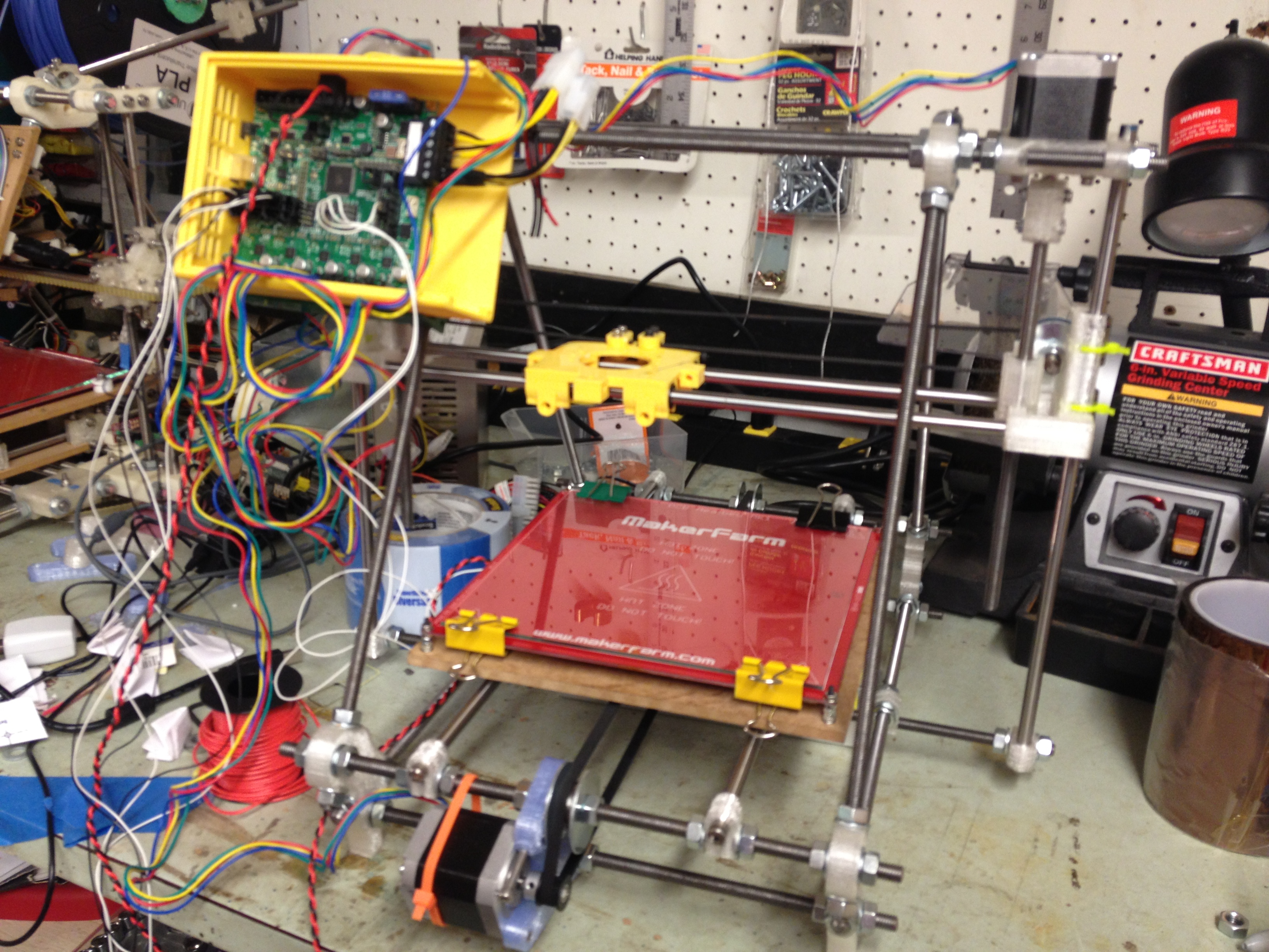
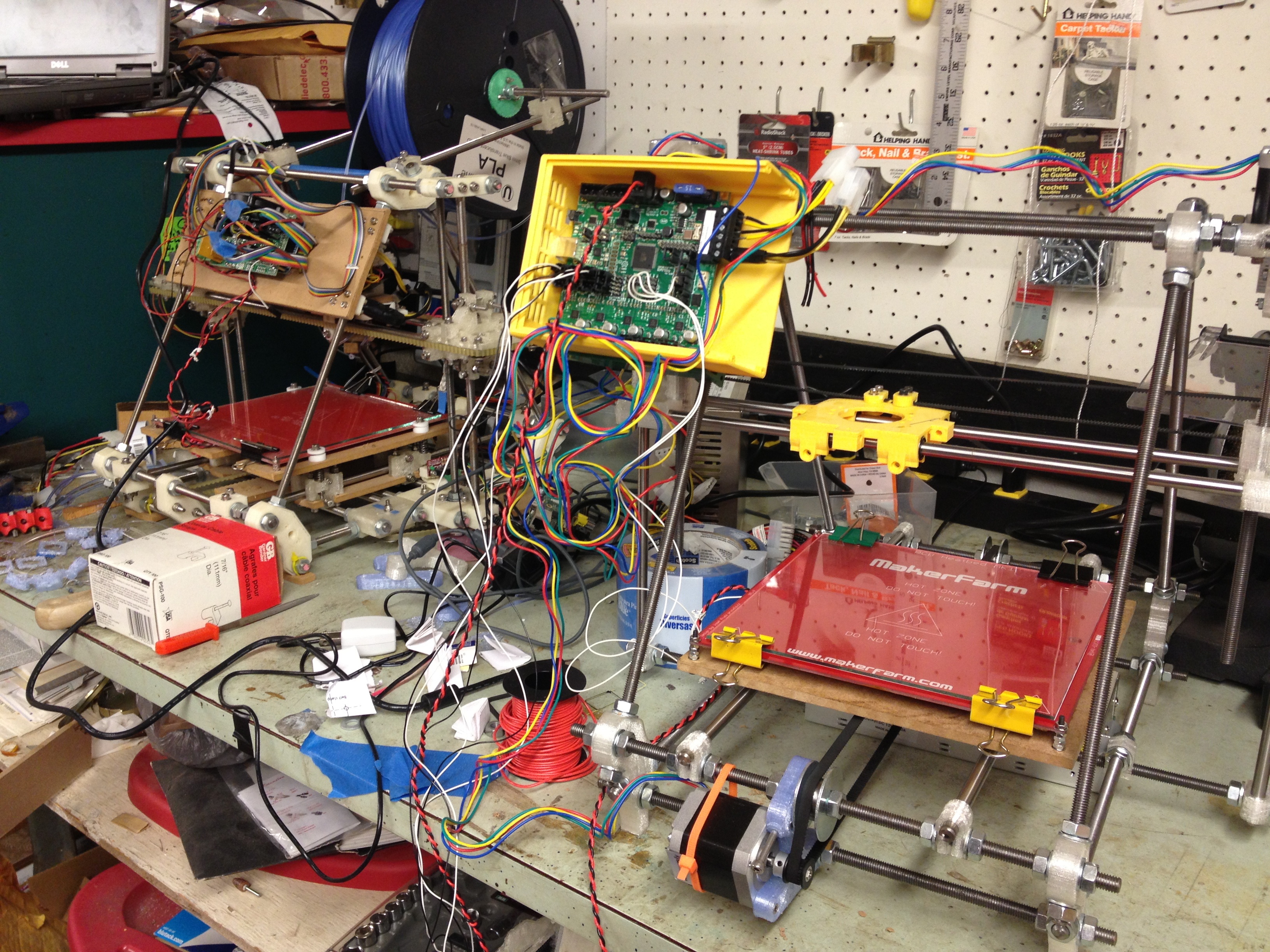
Here is what the RepRap looked like with the bed mounted:
…and here it is next to its parent, my original RepRap (an original “Sells” Mendel):
Note in that picture I also had my RAMBo box mounted. I installed it on the frame (with one of these, although note to self: I should upload the slight change I made to that to get it to fit my upper bars since I have the extra nuts up there).
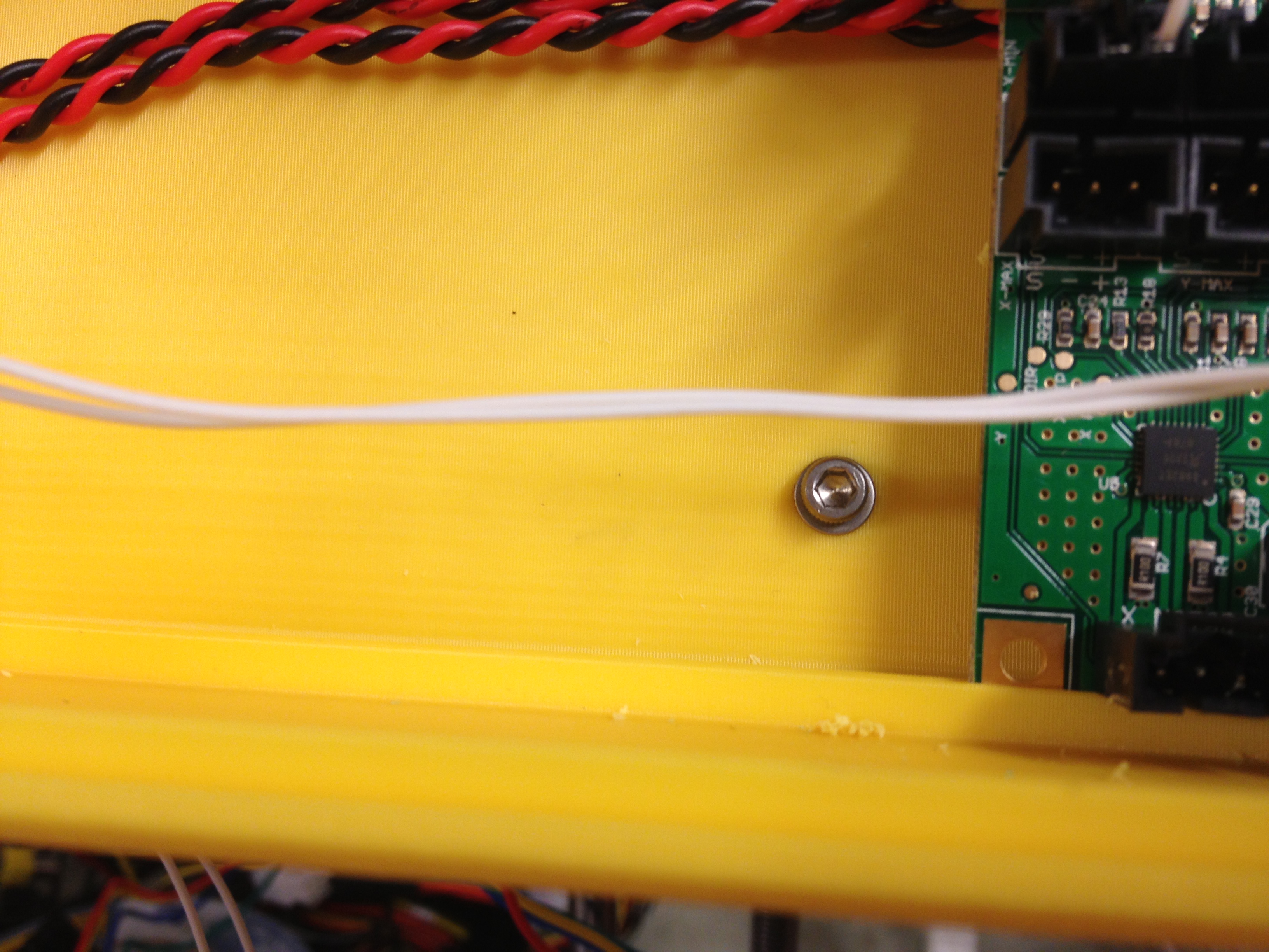
I permanently mounted my RAMBo Box on the green holder piece, as you can see by the screw in the middle behind the board in the next two pictures. I basically held it in place and drilled a hole through, then fastened it with a bolt, two washers, and a nut.
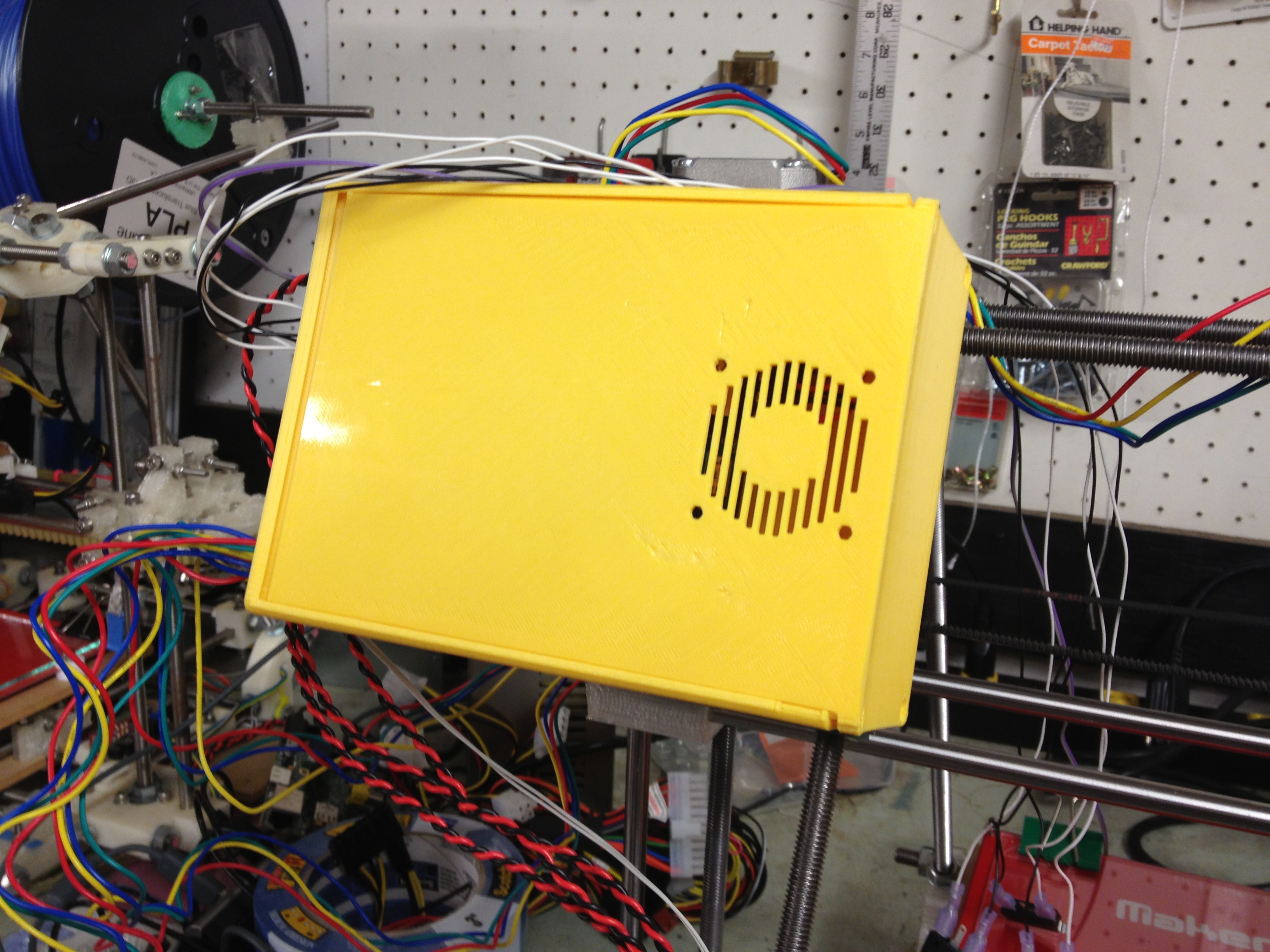
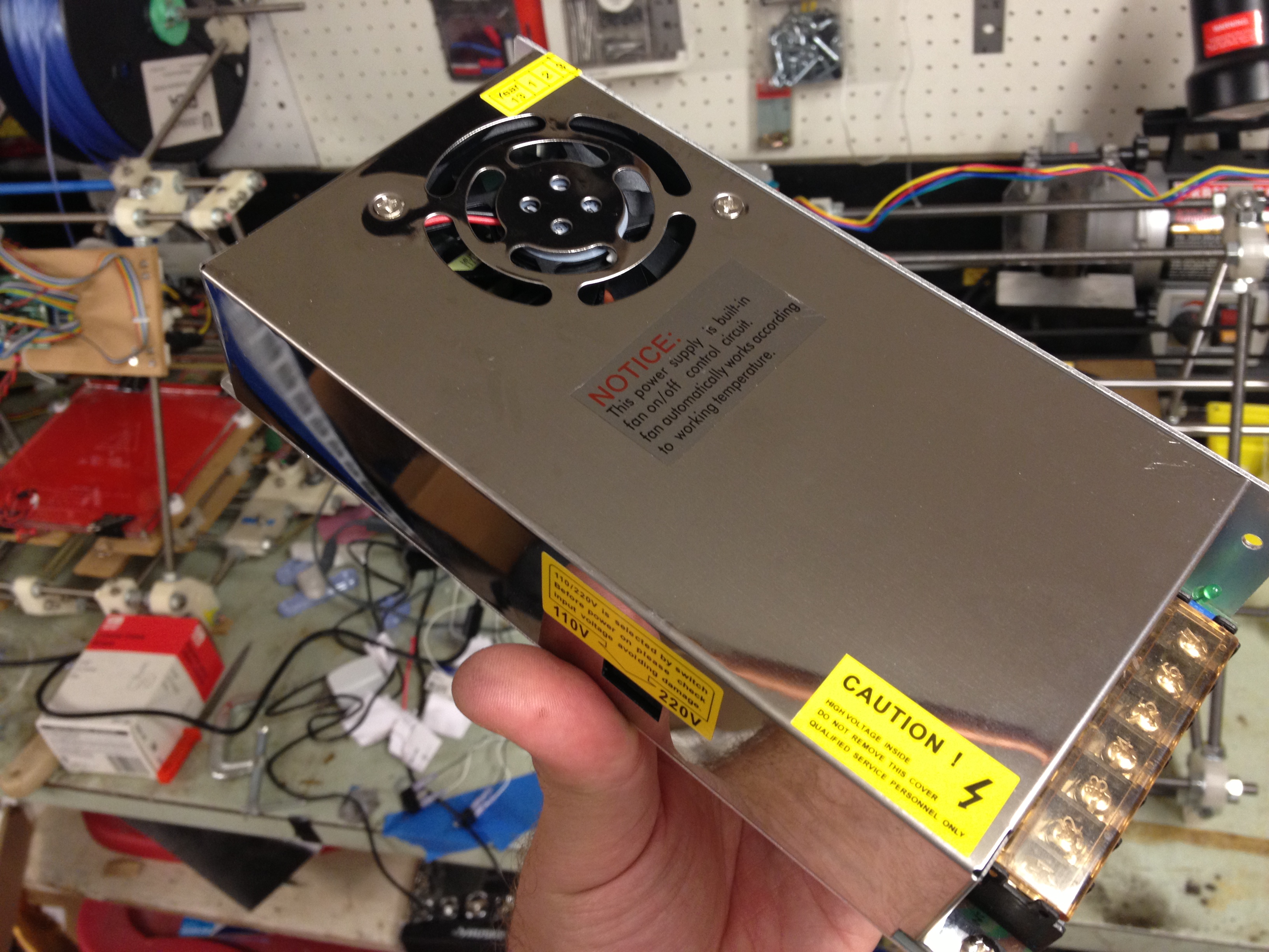
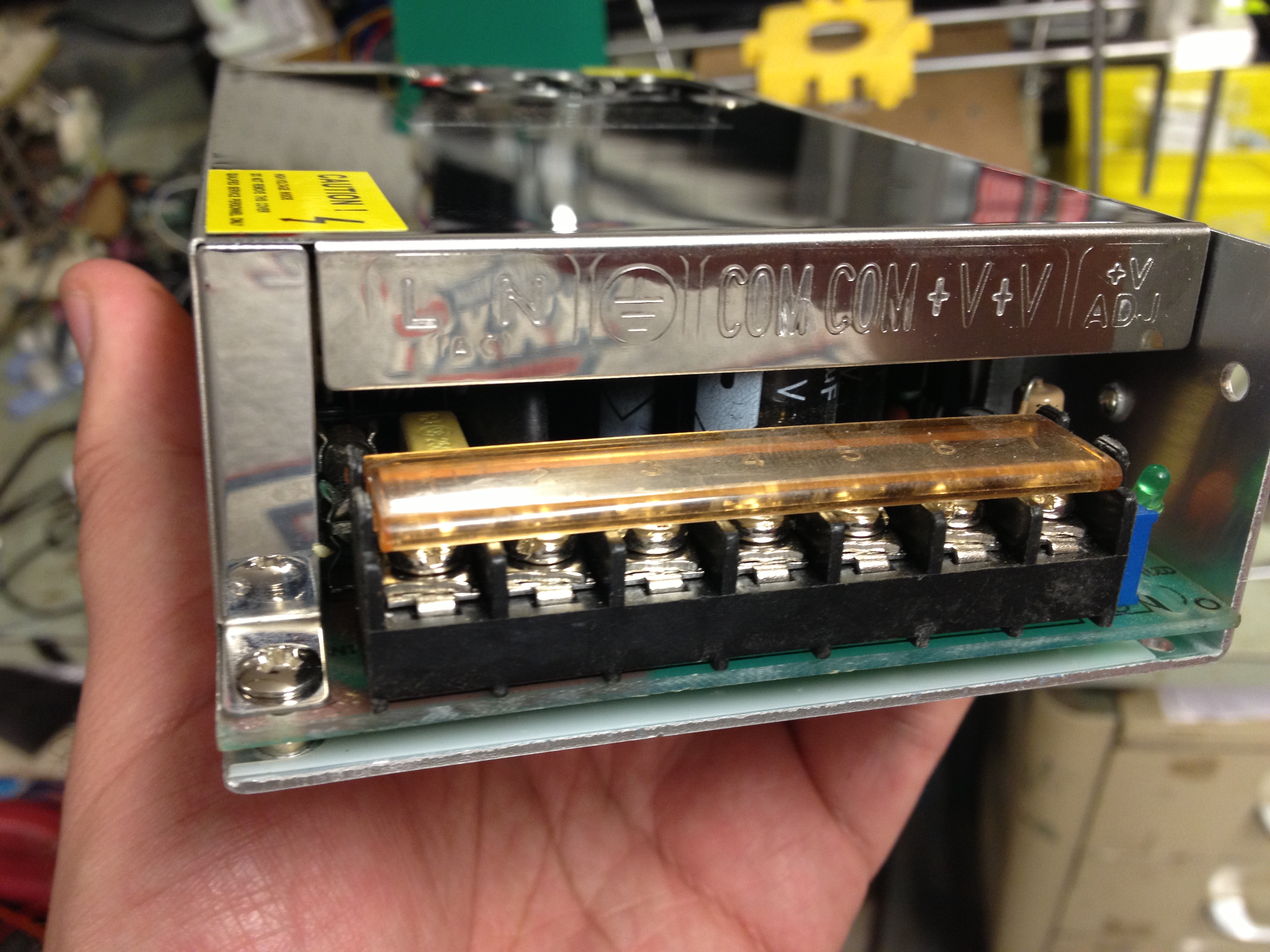
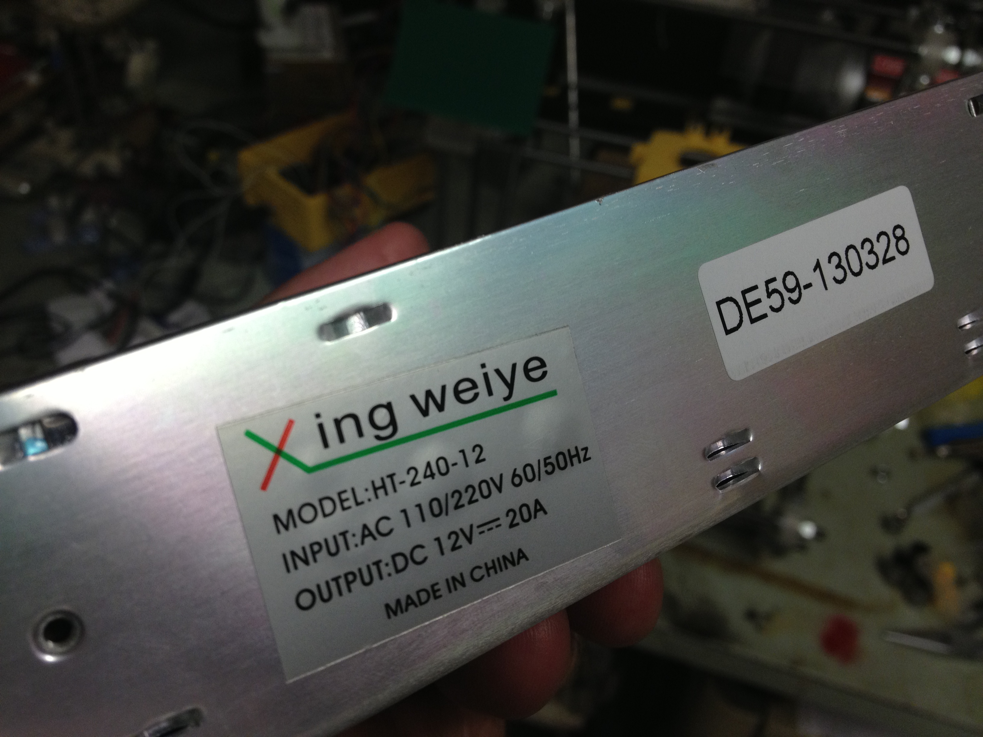
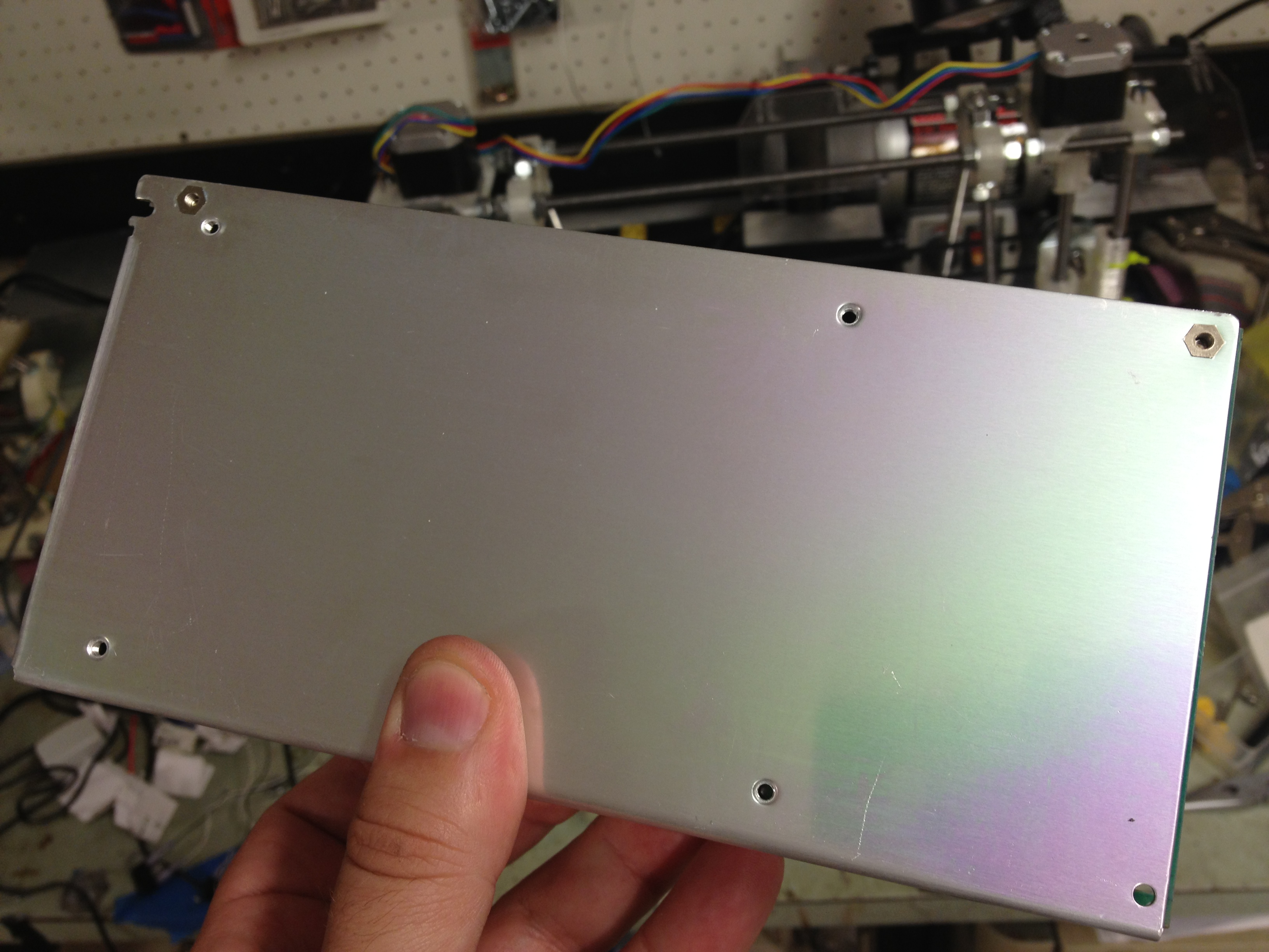
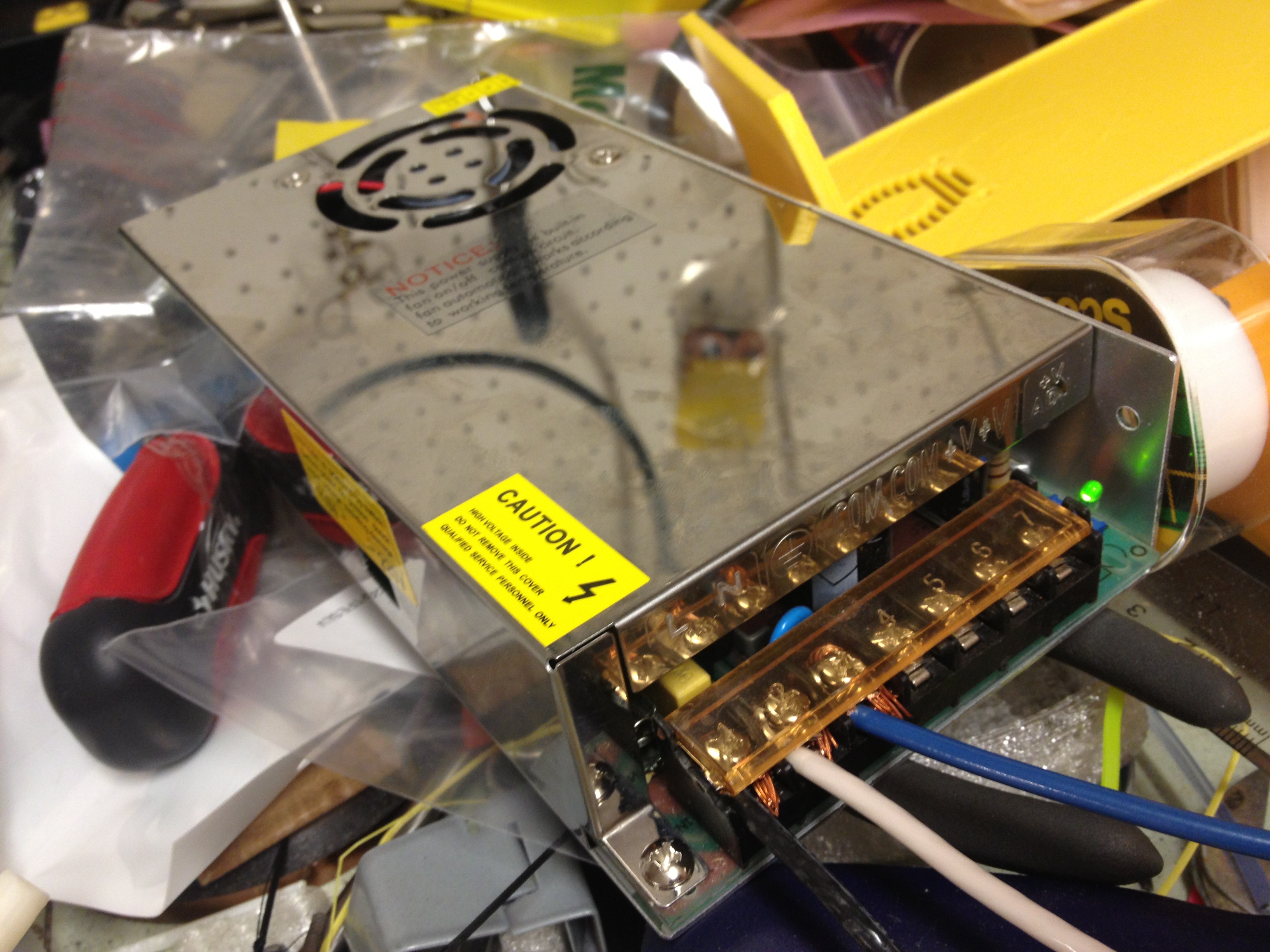
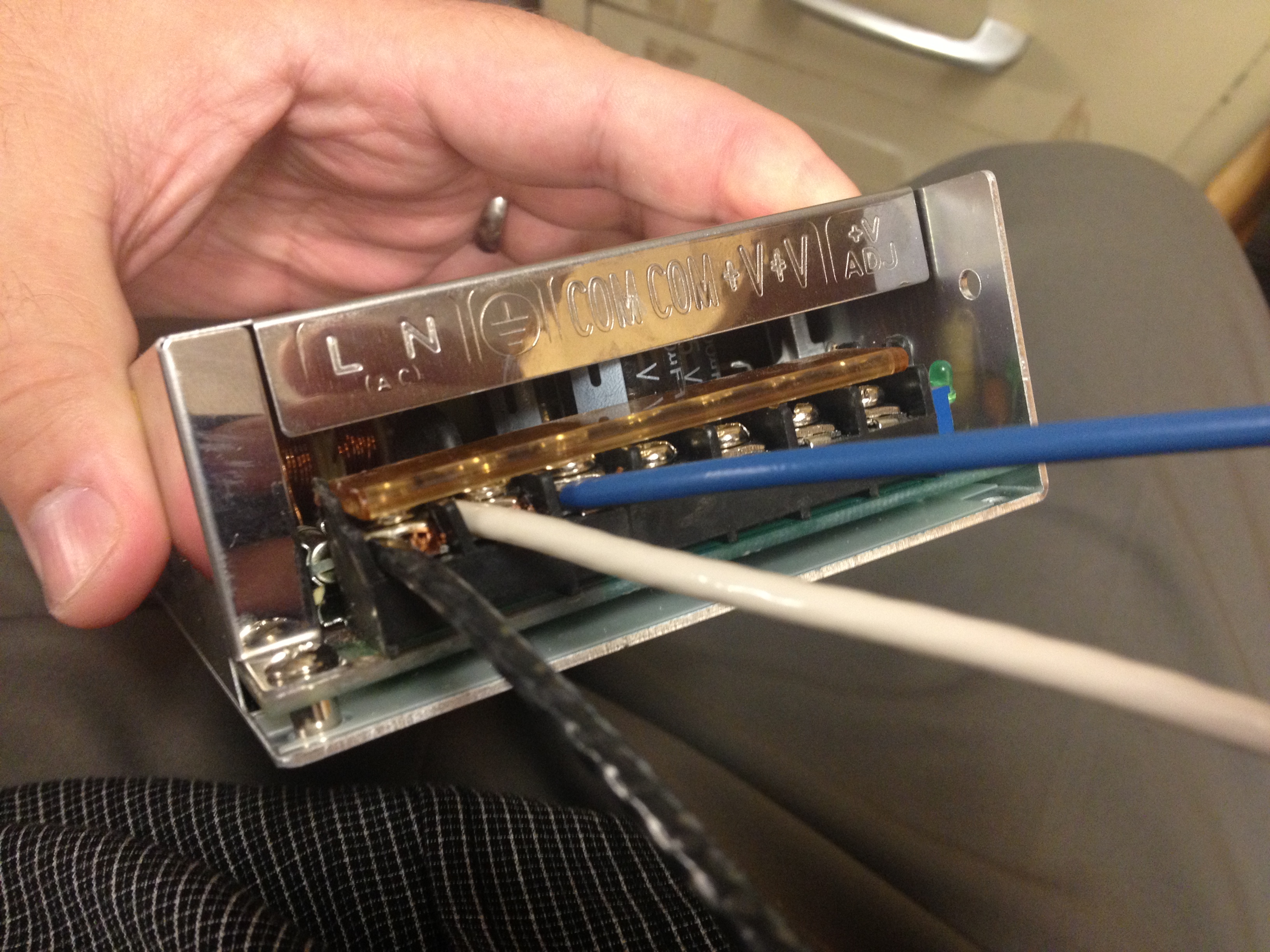
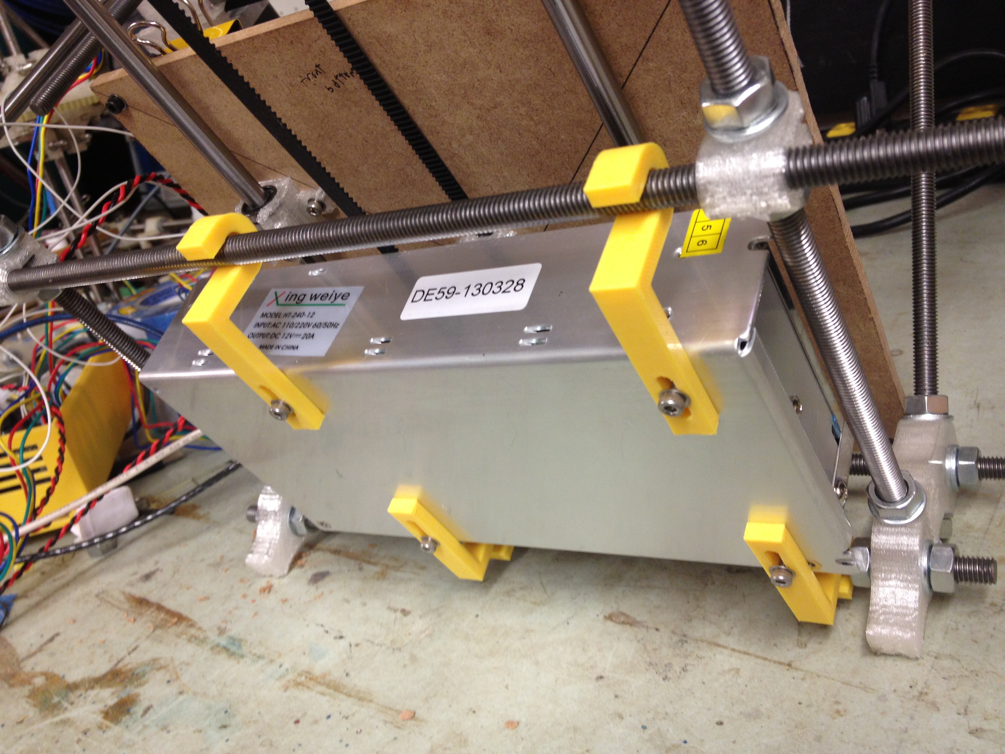
As for power, this time around I wanted a bit more of a self-contained RepRap than my first one, which has a computer power supply dangling off of it and a ton of wires. I bought this power supply, which I wanted to mount below the bed:
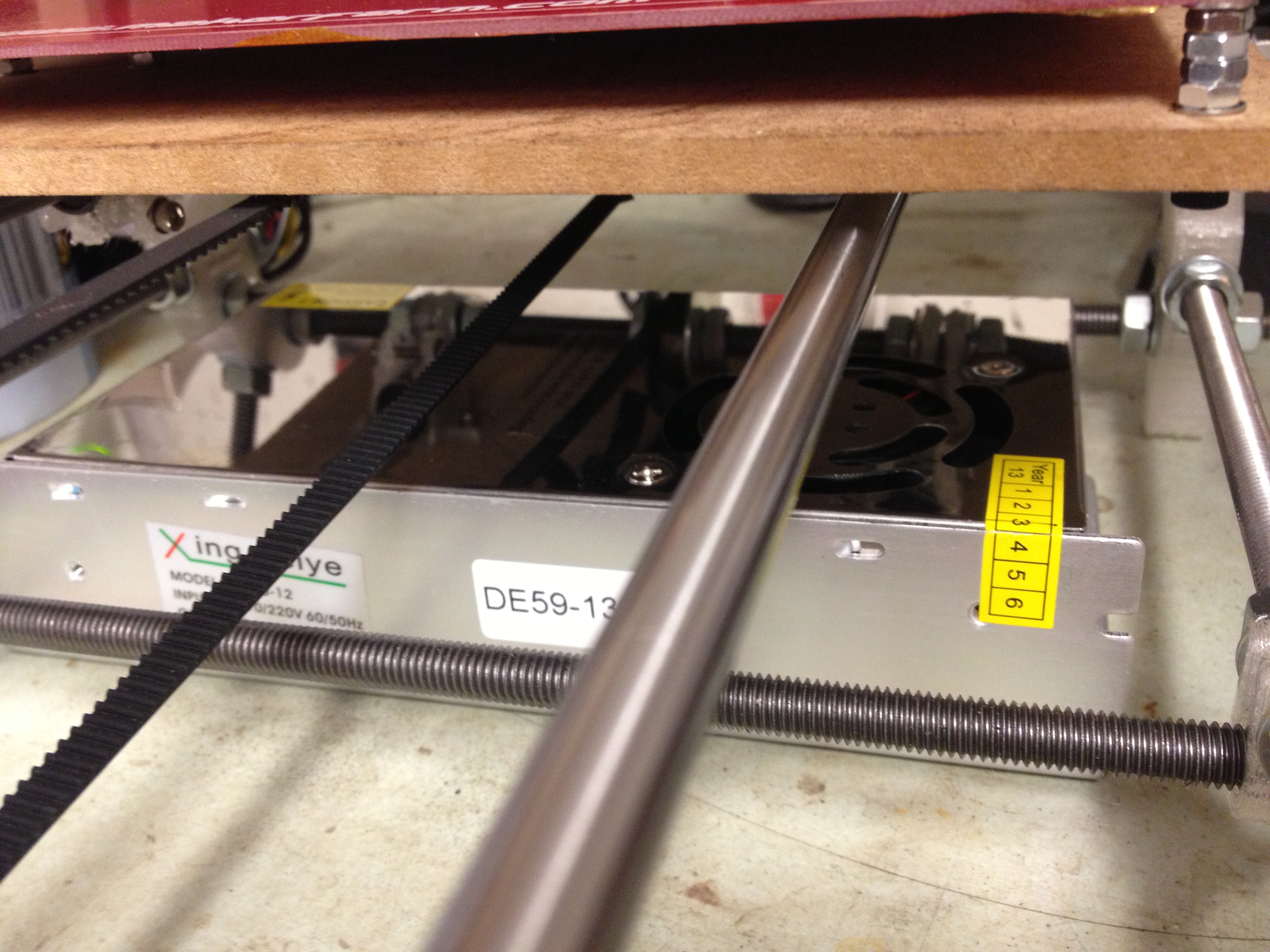
At first I just rested it beneath the RepRap until I could get something better set up:
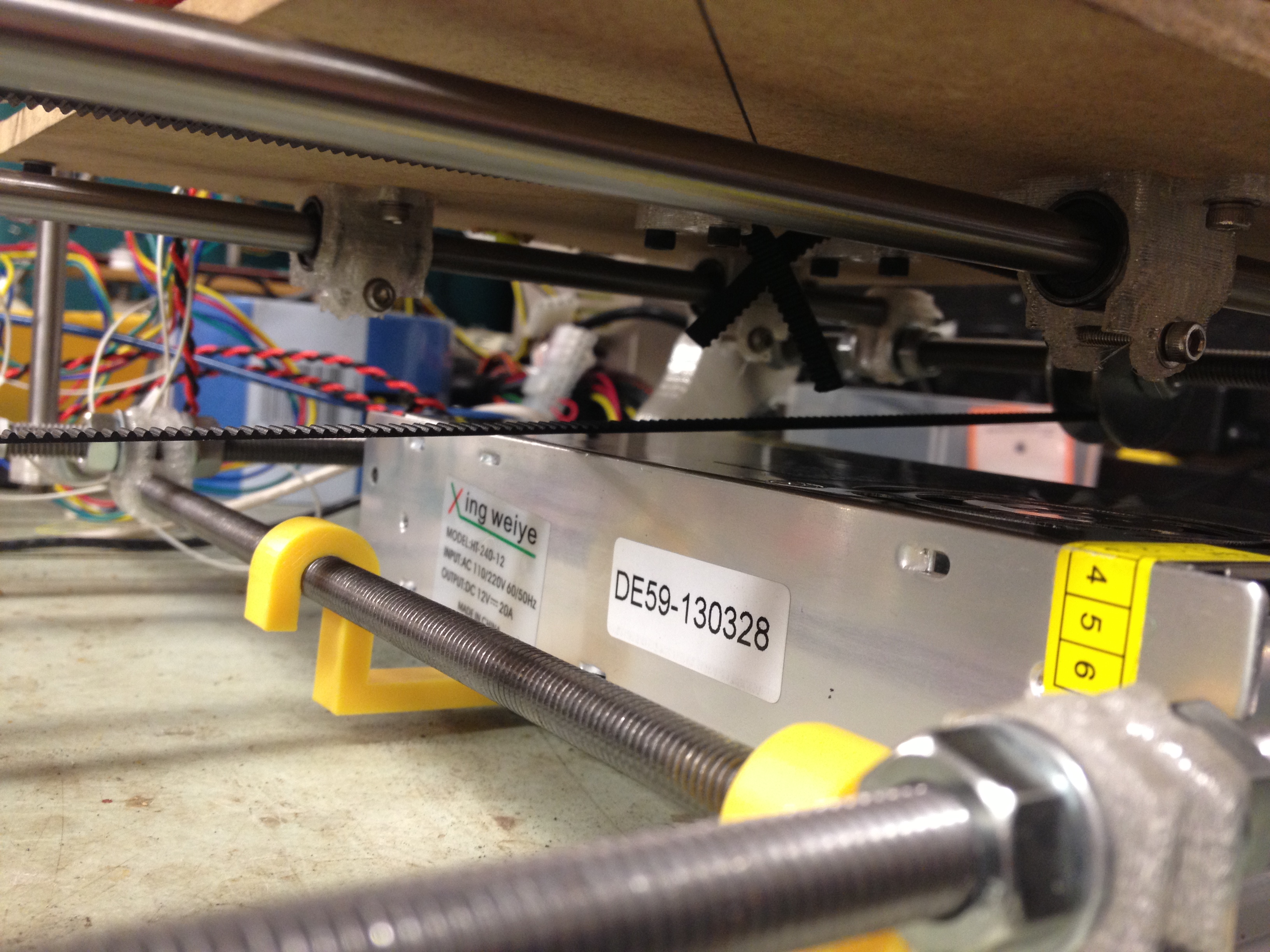
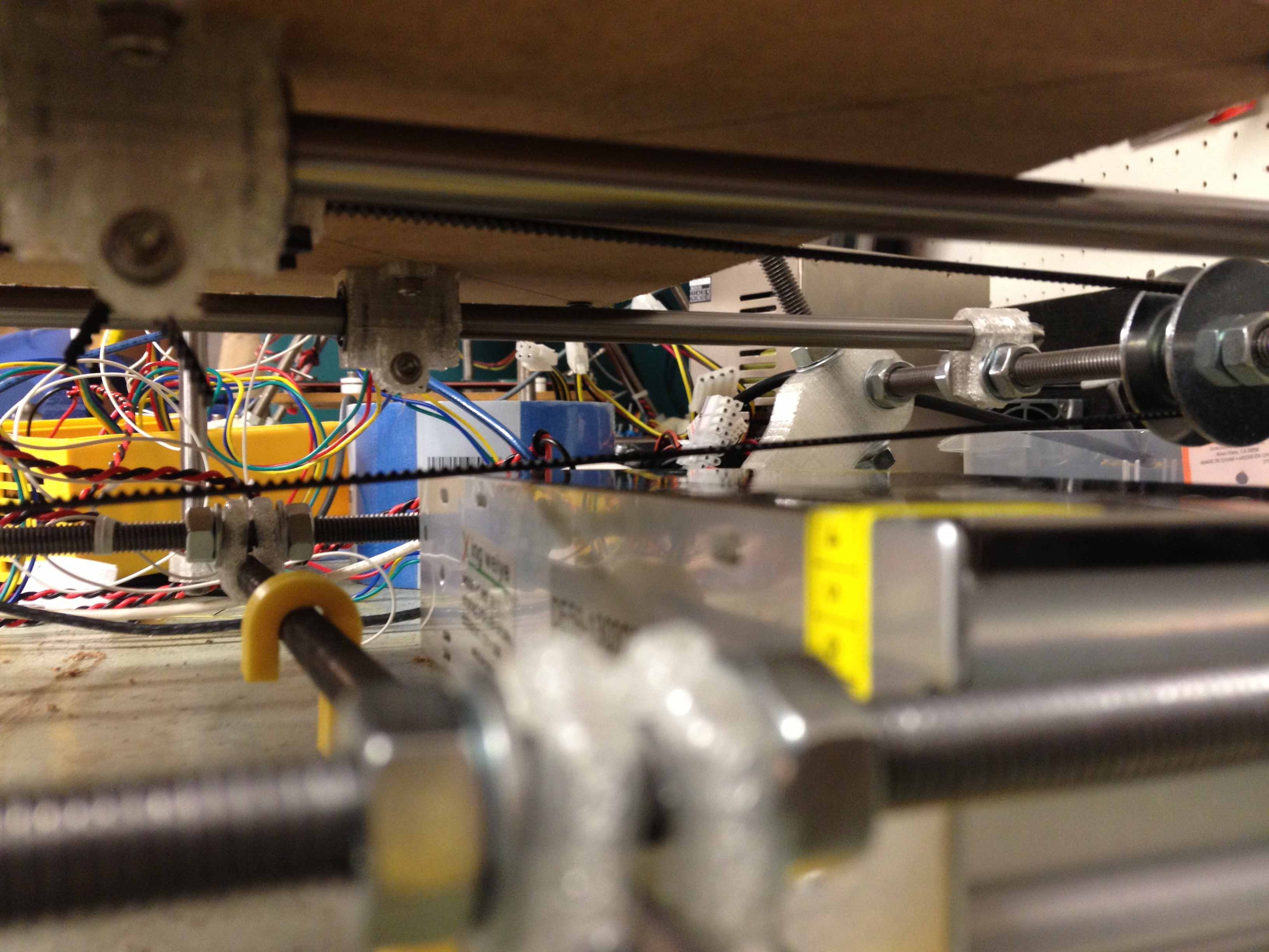
I made sure that the Y belt didn’t hit the power supply.
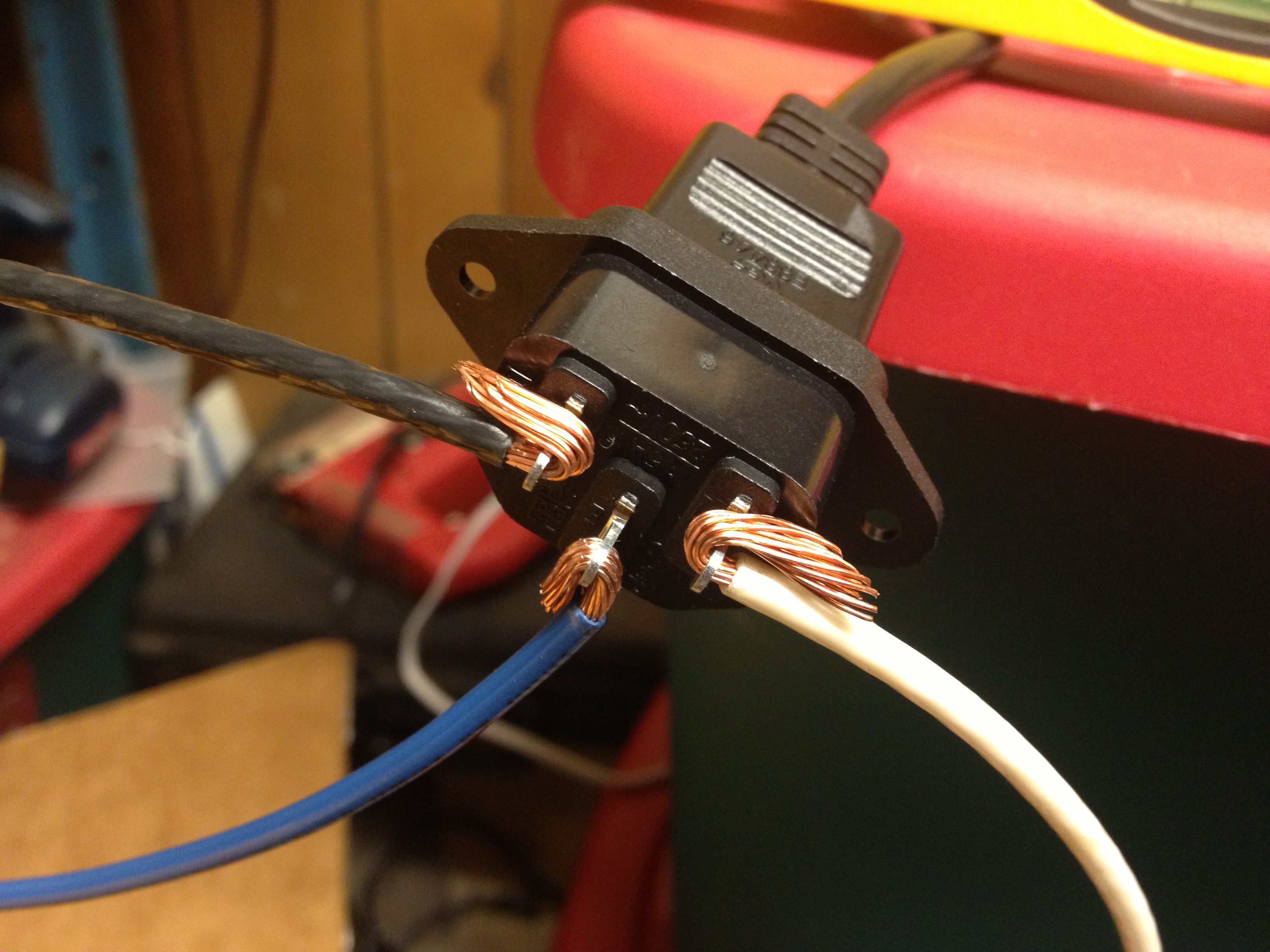
The first time that I wired it up to try using it for power, it looked like an electrician’s nightmare. Don’t follow my example as instructional – I was super cautious but don’t recommend testing things out this way.
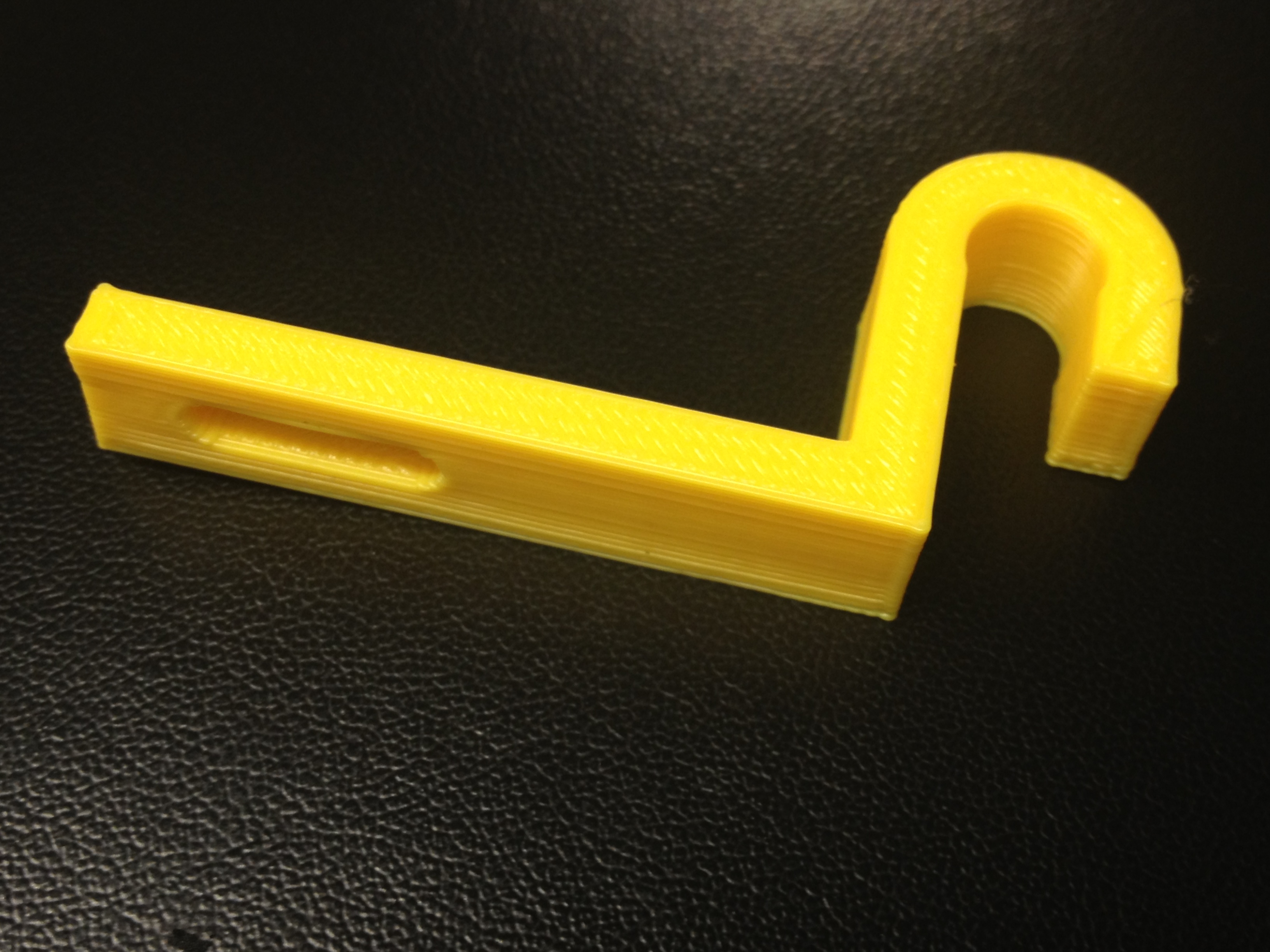
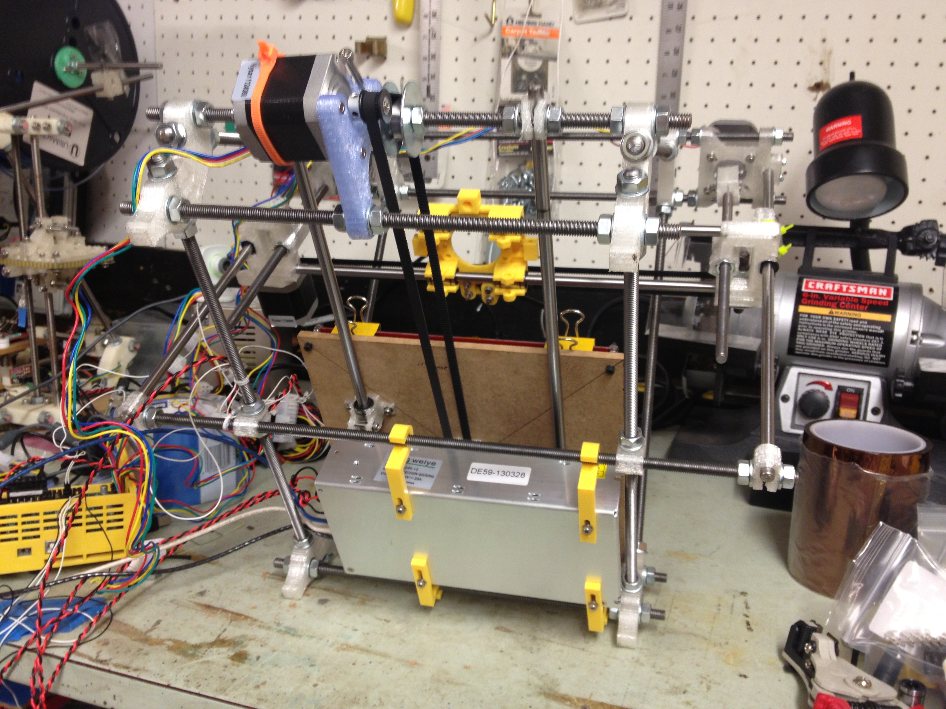
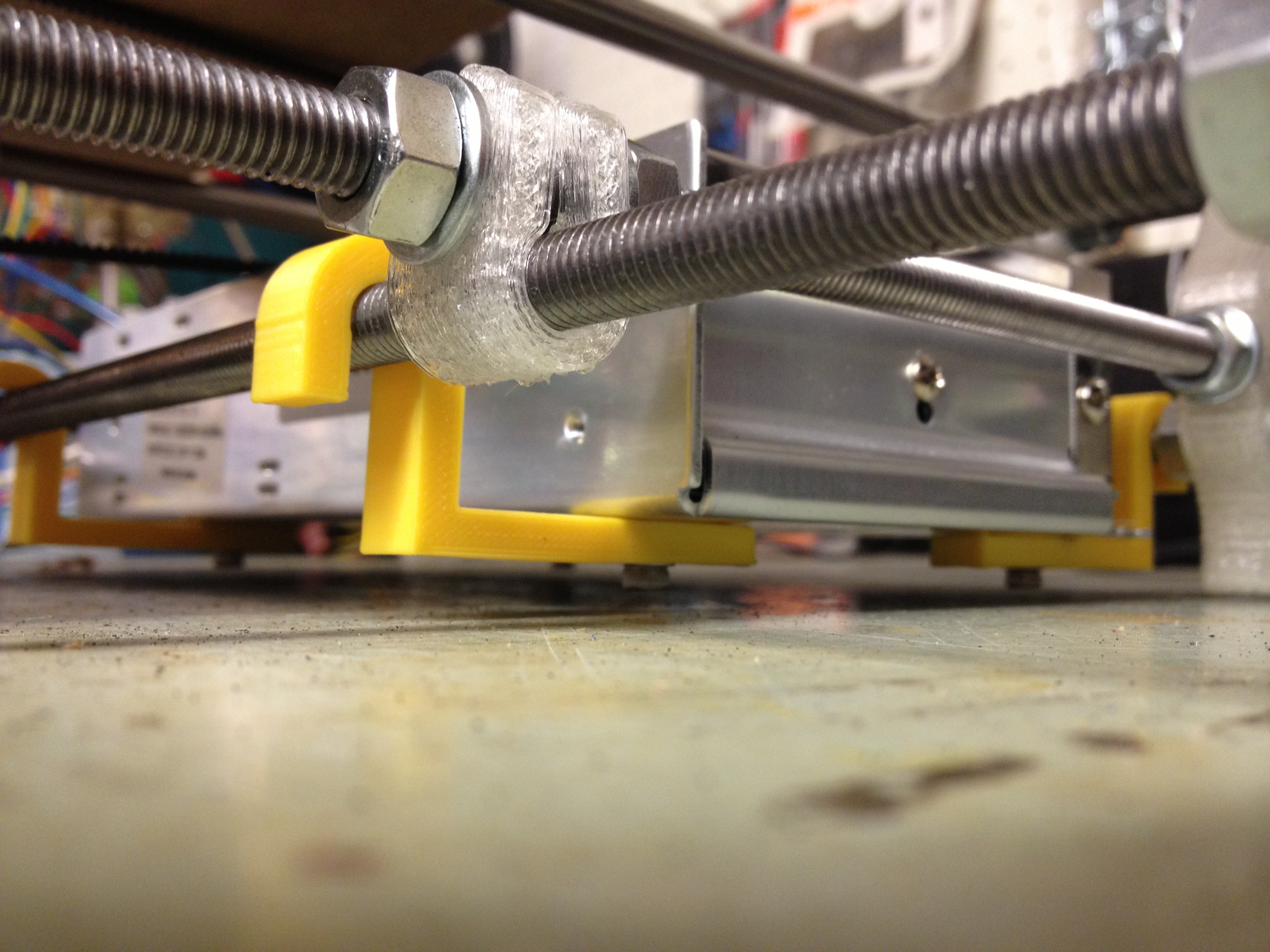
I printed a few of these holders for the power supply designed by my friend Chris, so it can hang from the bottom bars below the bed.
Here it is, mounted:
The y-belt still just barely clears it..
Here’s a tragically truncated video describing it:
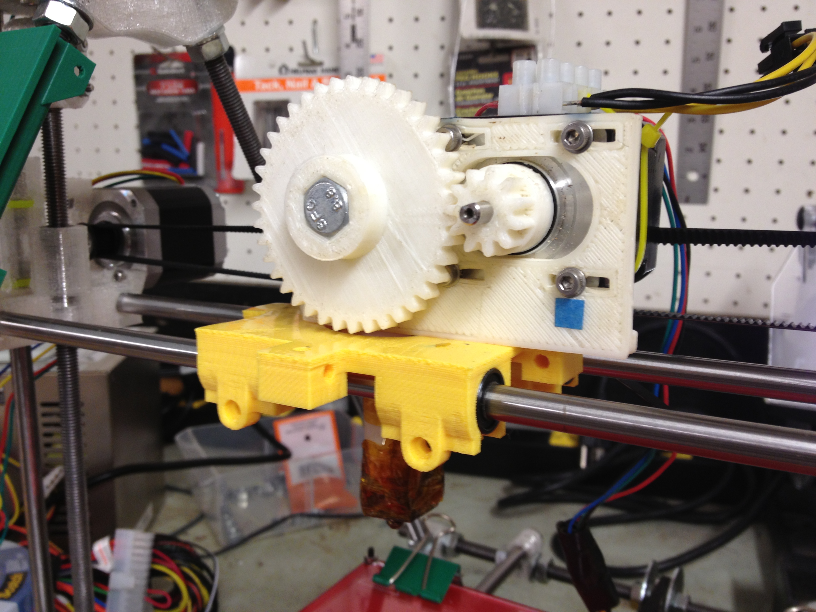
Trying to move as quickly as possible, I attached my old Wade’s extruder to the carriage, since I had it lying around.
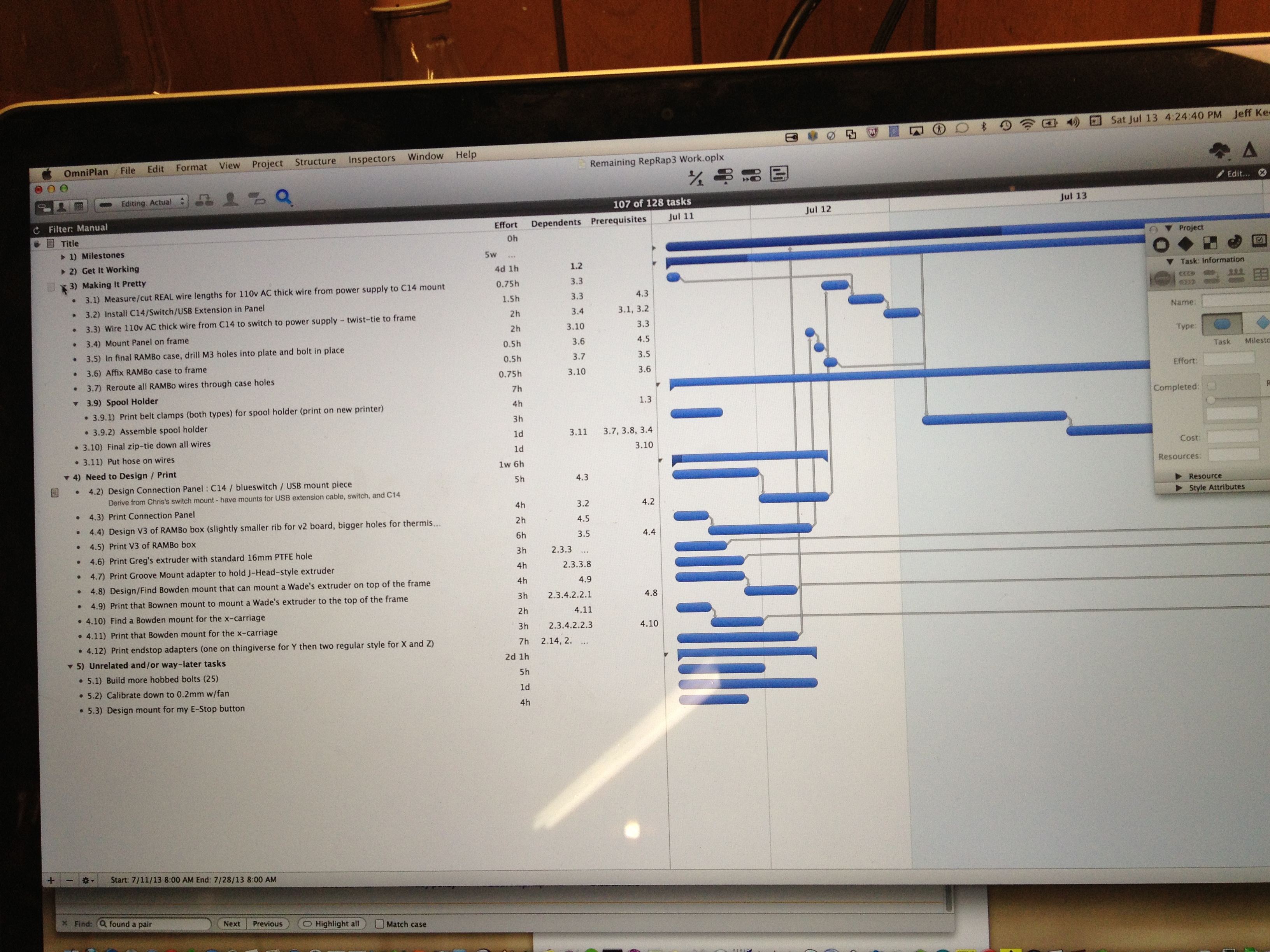
I was in such a rush to get this done (and under so much self-imposed pressure, both for an upcoming RepRap gettogether and eventually Makerfaire 2013) that I actually found myself marking off projects in a project management tool (in my case, OmniPlan). I know. And yet, it helped.
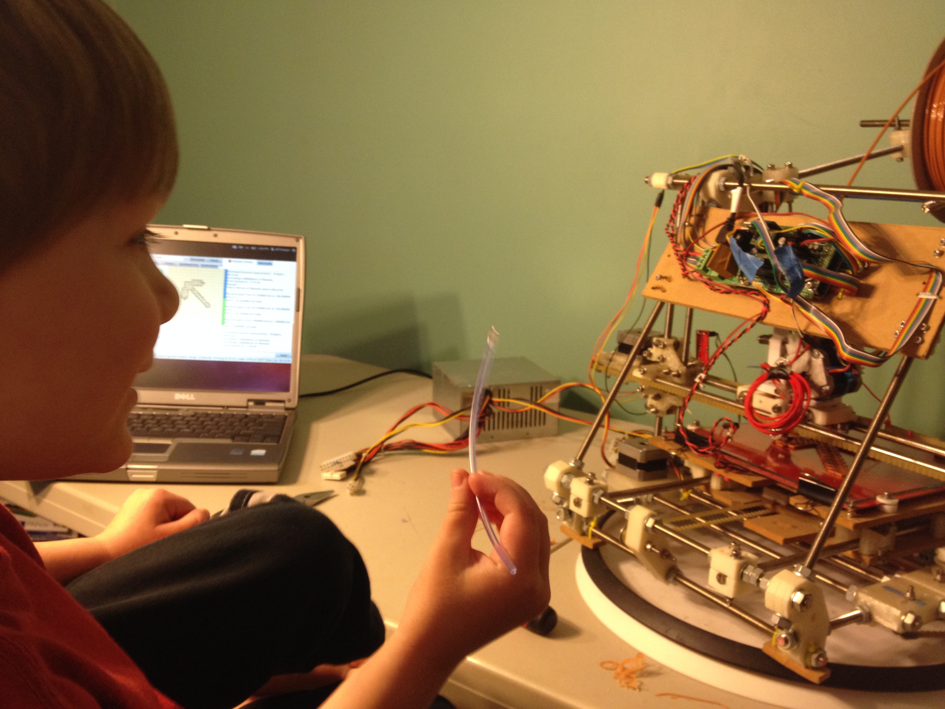
And here’s a video of me printing on my original RepRap, waiting to try printing on my new RepRap. I hadn’t yet gotten the hang of driving two RepRaps from the same laptop, which I’d later master. 🙂
Here was the result of that print on my original RepRap, showing some new rice-crispies like failure:
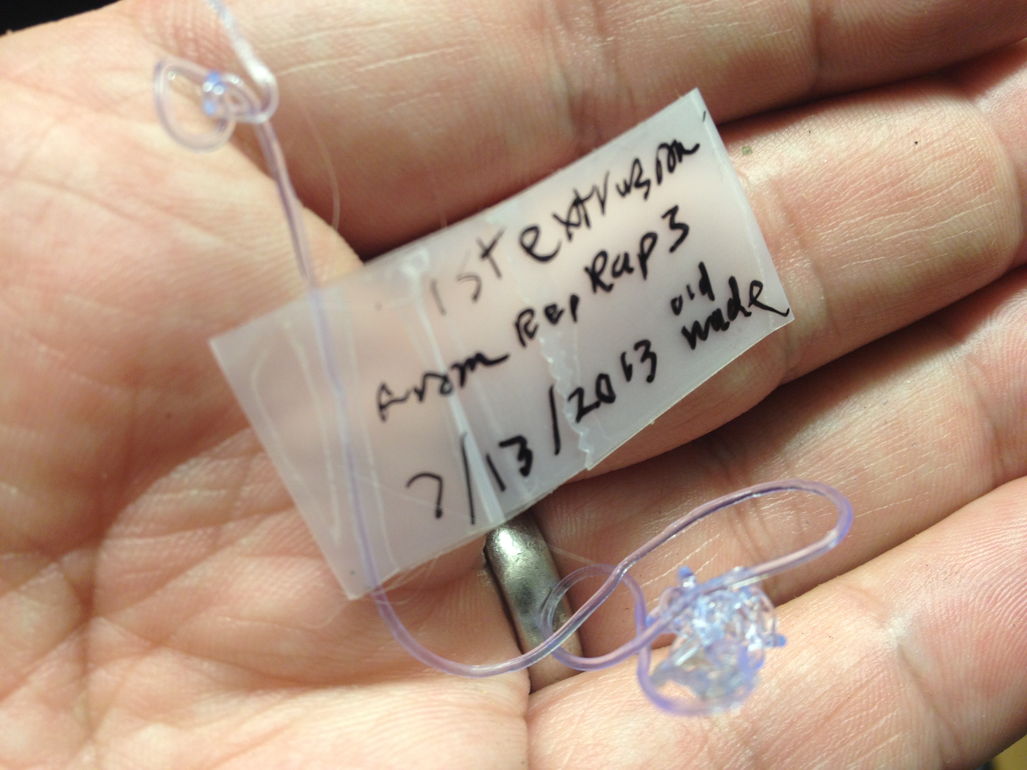
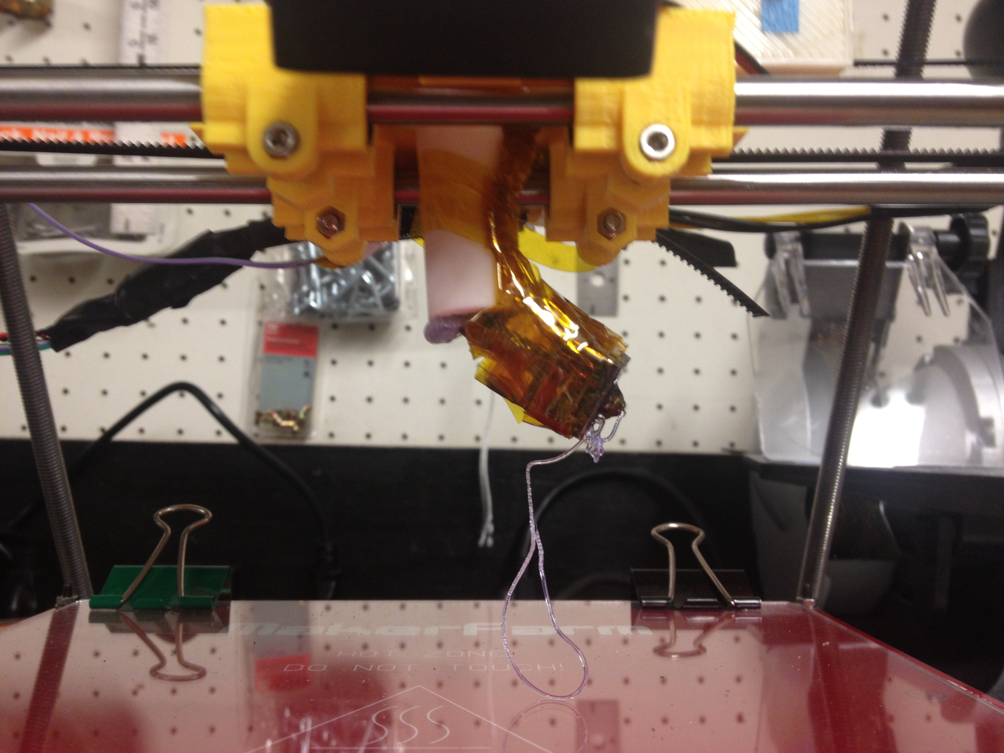
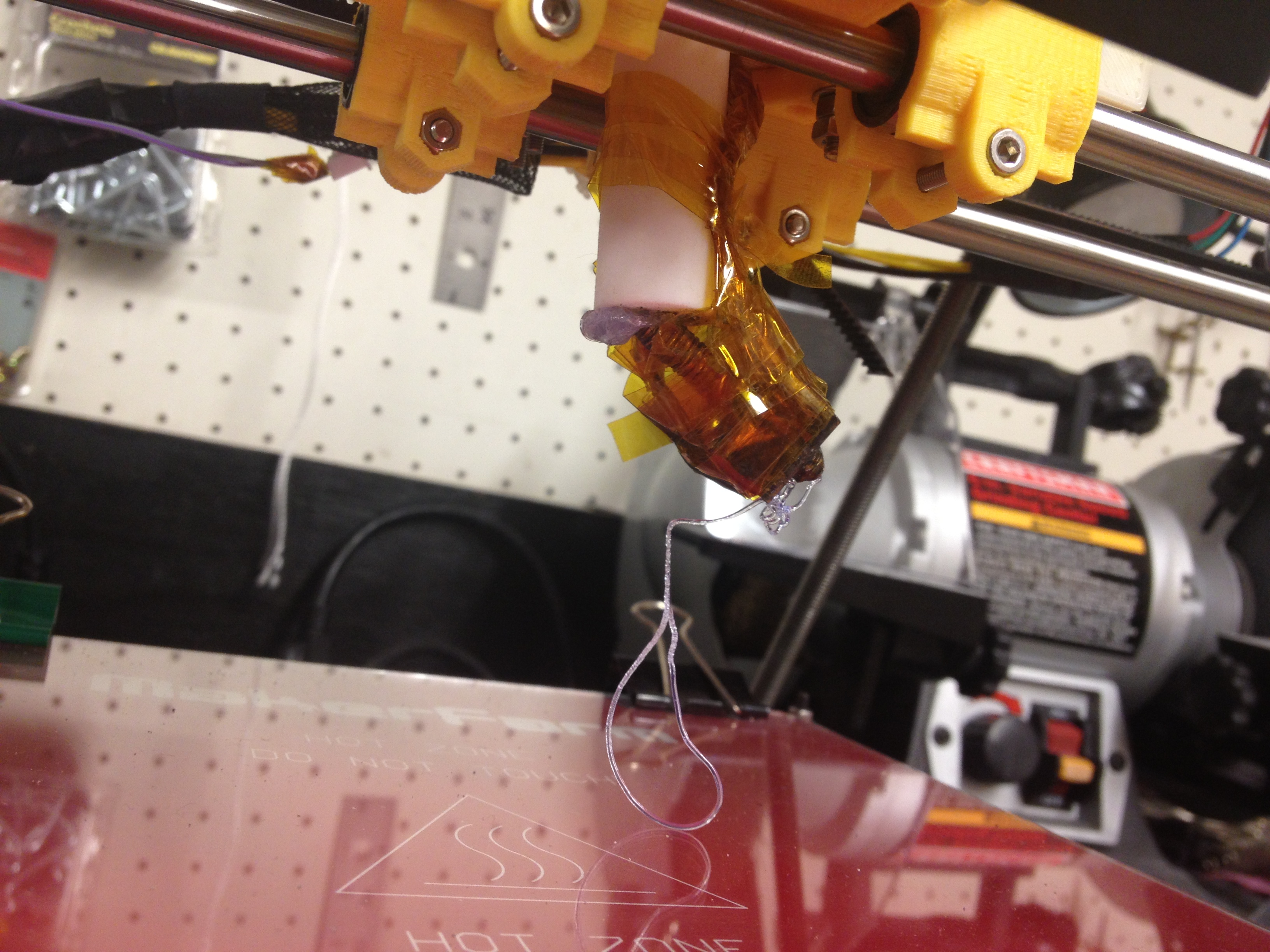
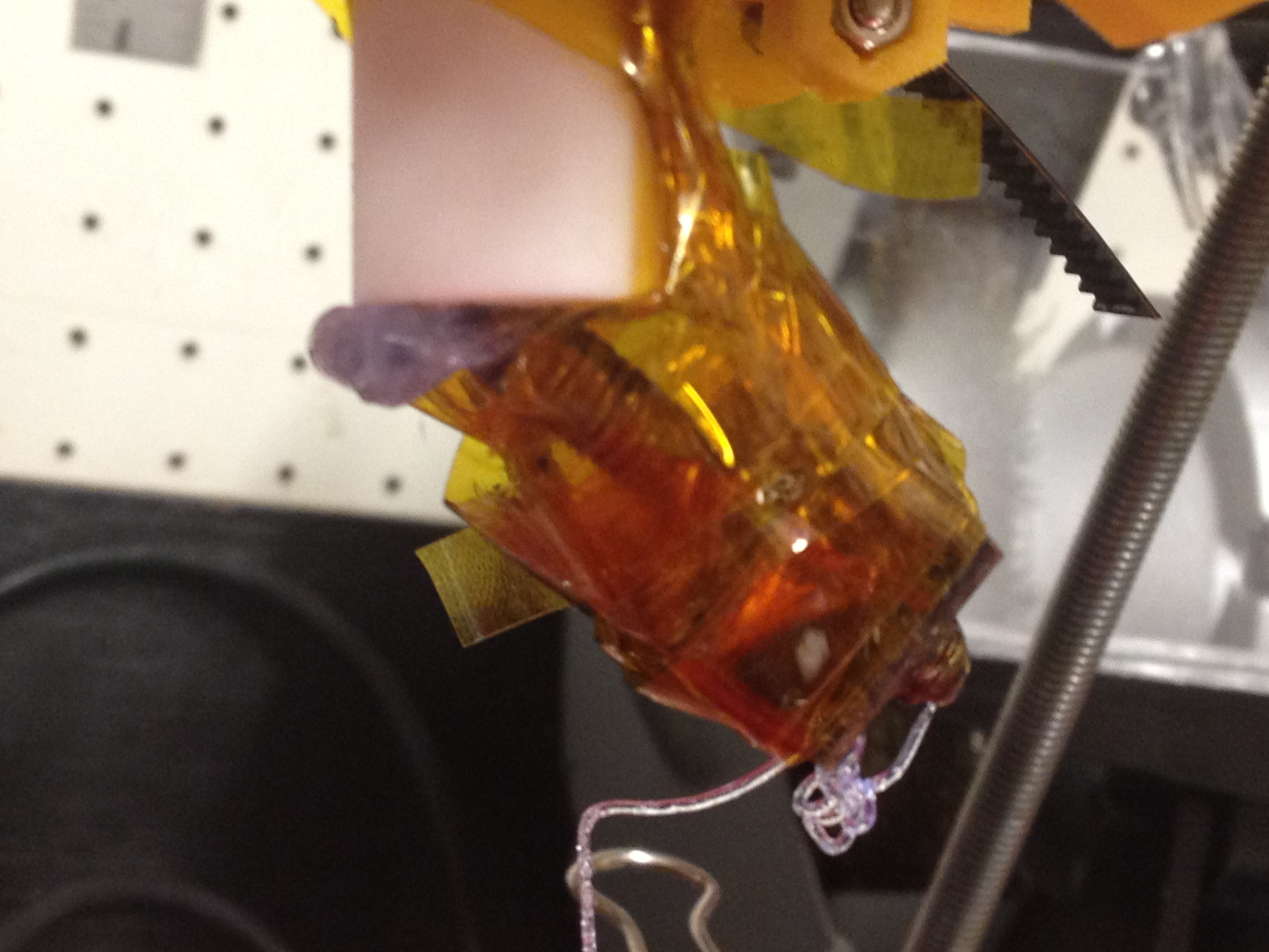
So I tried extruding plastic on my new RepRap, and here was its first extusion:
It then, however, failed.
I hate ending on a bad note like that, but I have to go to bed because tomorrow I’m driving to New York for Makerfaire 2014. I know, I still haven’t blogged about Makerfaire 2013!! I was hoping to get to it – I’m about one or two posts away from it, but it doesn’t look like I’m going to have time. We’re now caught up to July 16th 2013, while today’s actual date is early in the morning of September 18th, 2014.
Reminder: In two days I’m going to exhibit at Makerfaire NY 2014, for my third time. Buy your tickets now and come see me! If I can drag two RepRaps down in a car from the north end of Massachusetts to Queens, New York, you can drag yourself down there.. it’s a great time!