Last post, I had us caught up to January 23rd 2013. Let’s keep going. Today is March 18th, 2014. Just over a year behind.
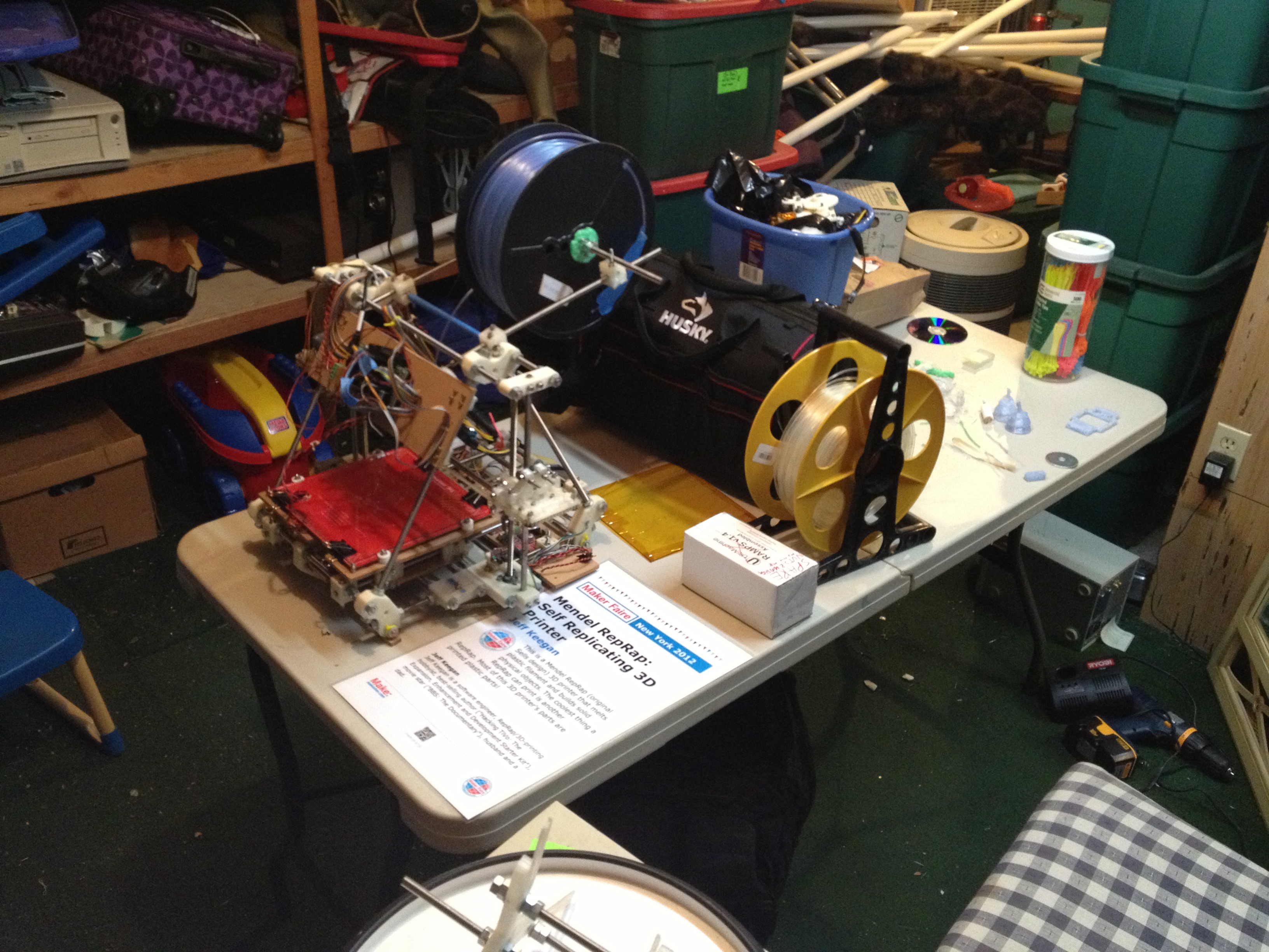
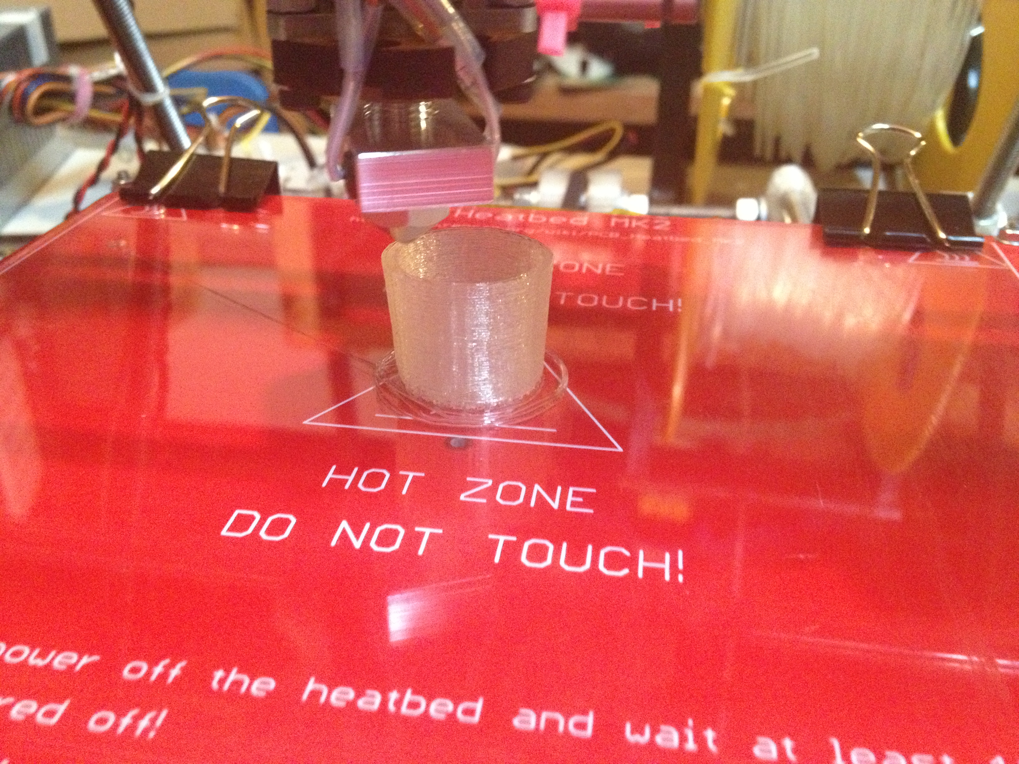
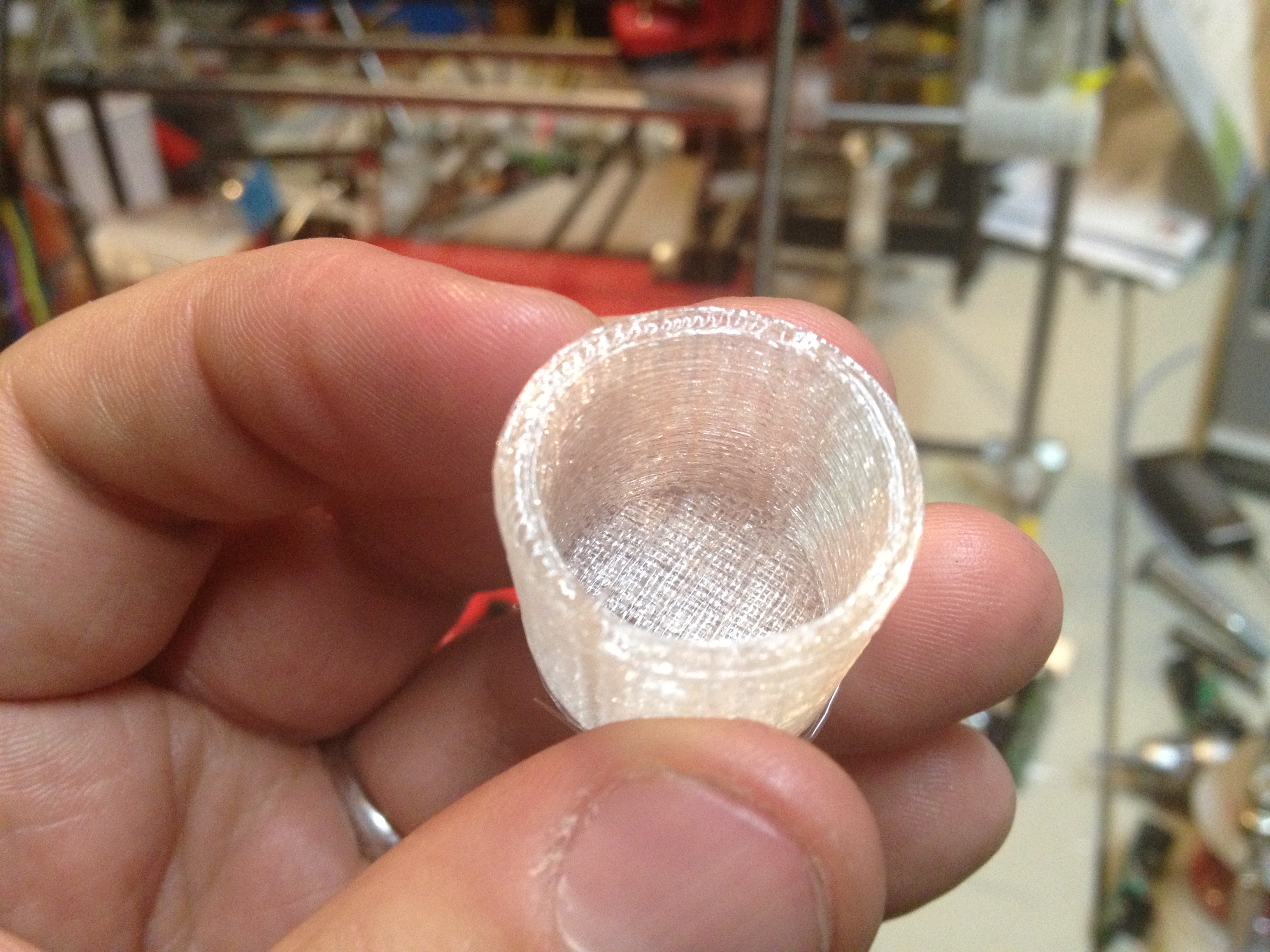
So I was working on the child RepRap that MY RepRap had built, so I could give it to the Museum of Science. During the last post I’d done its first print and the traditional minimug toast. Now I had to get the endstops working.
This was my first Prusa Mendel (IT2) build, so I didn’t know how the endstops would go on (in the original Sells Mendel the optical endstop mounts were all integrated into the build, but on the Prusa Mendel you have a lot of “flexibility”). I decided that I still wanted to use opto-endstops (vs mechanical ones), but that made it more difficult to figure out where the endstop flags should go (and I don’t like the idea of using glue for anything).
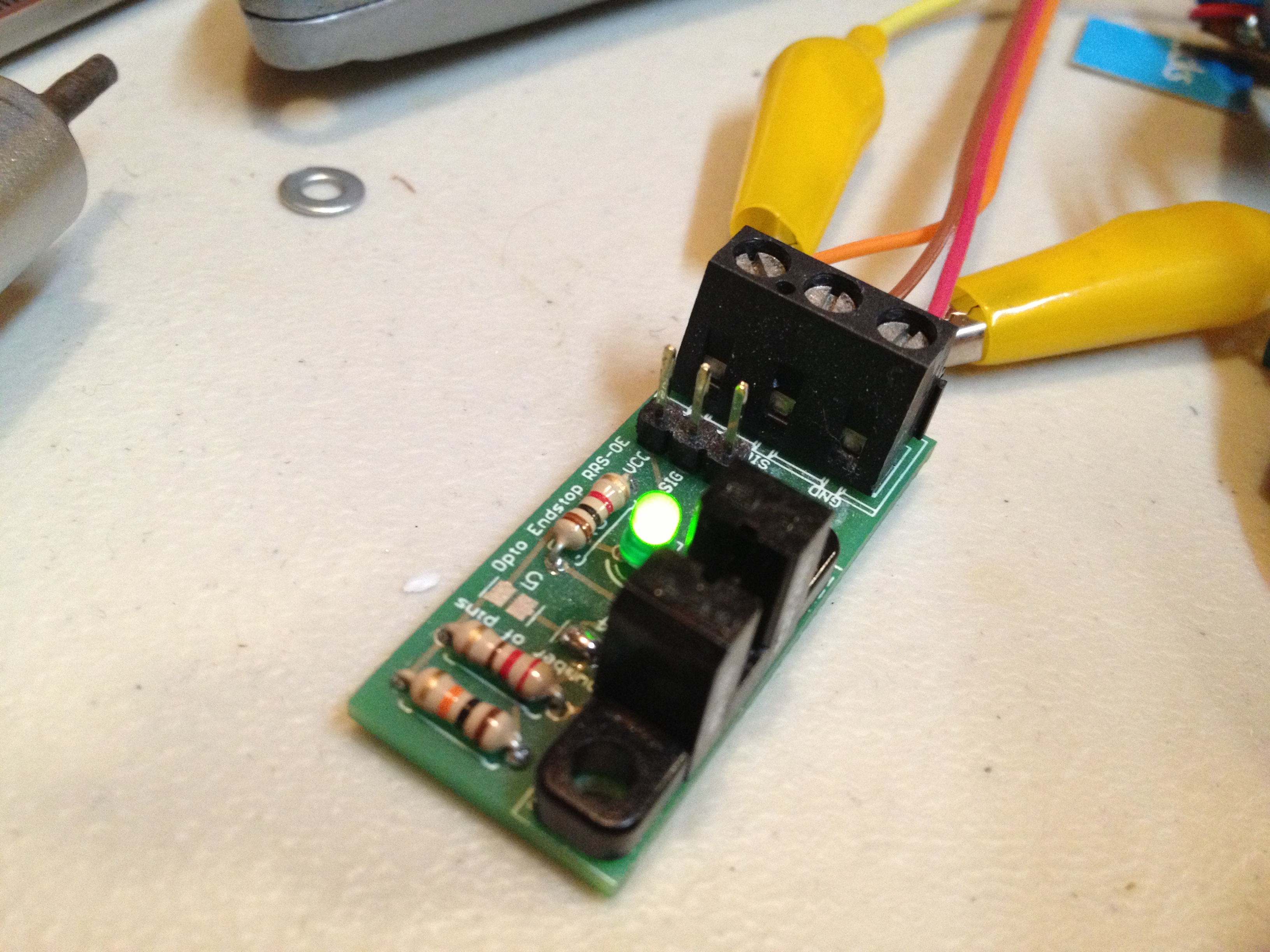
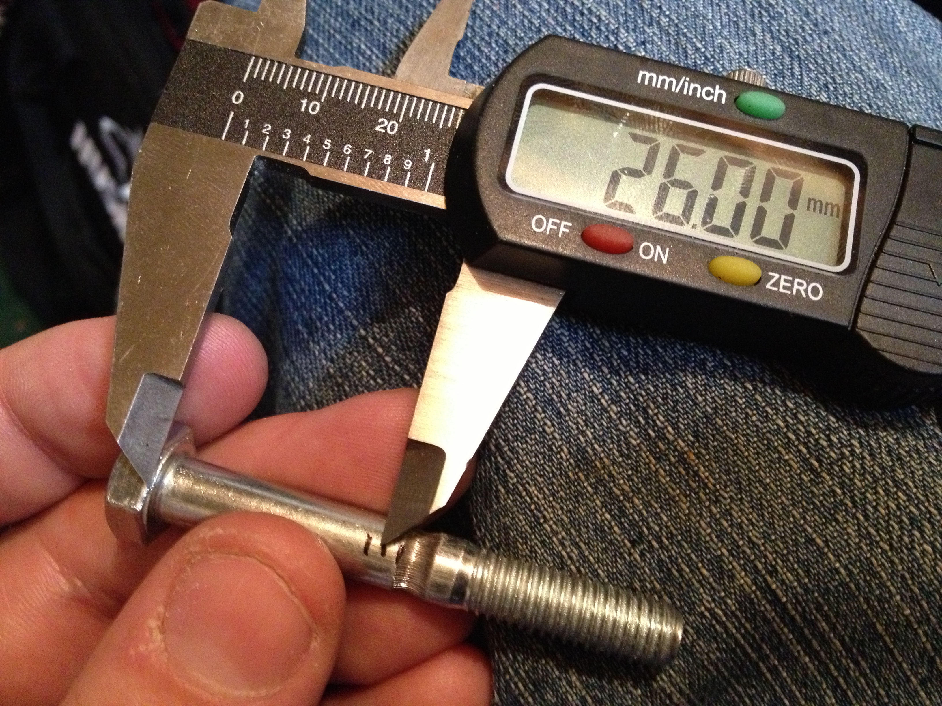
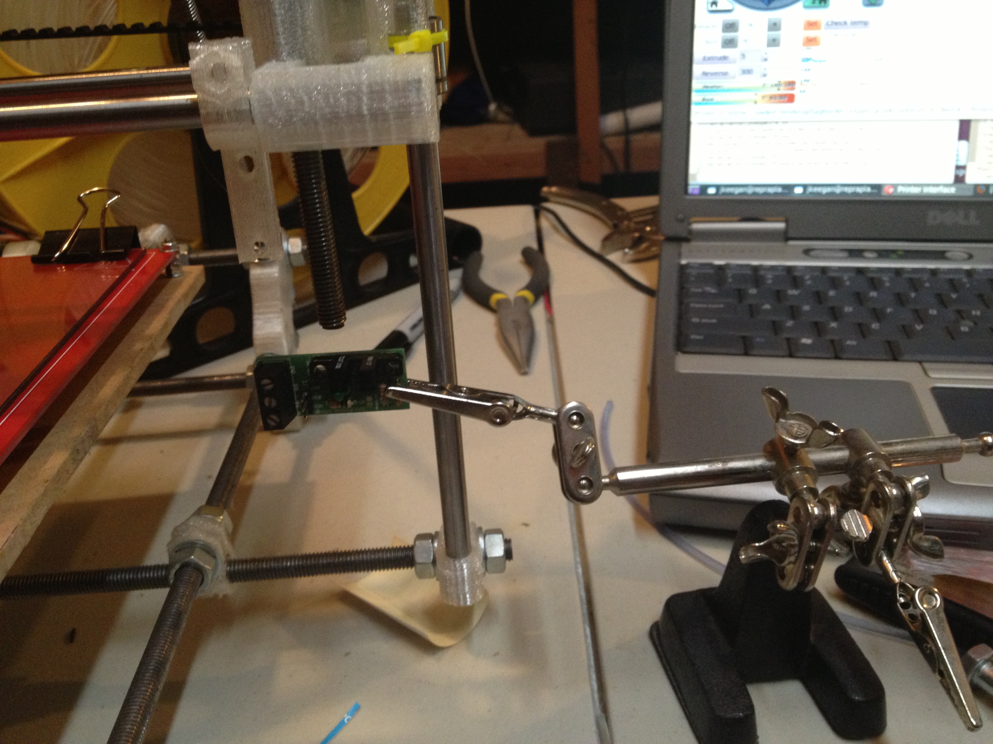
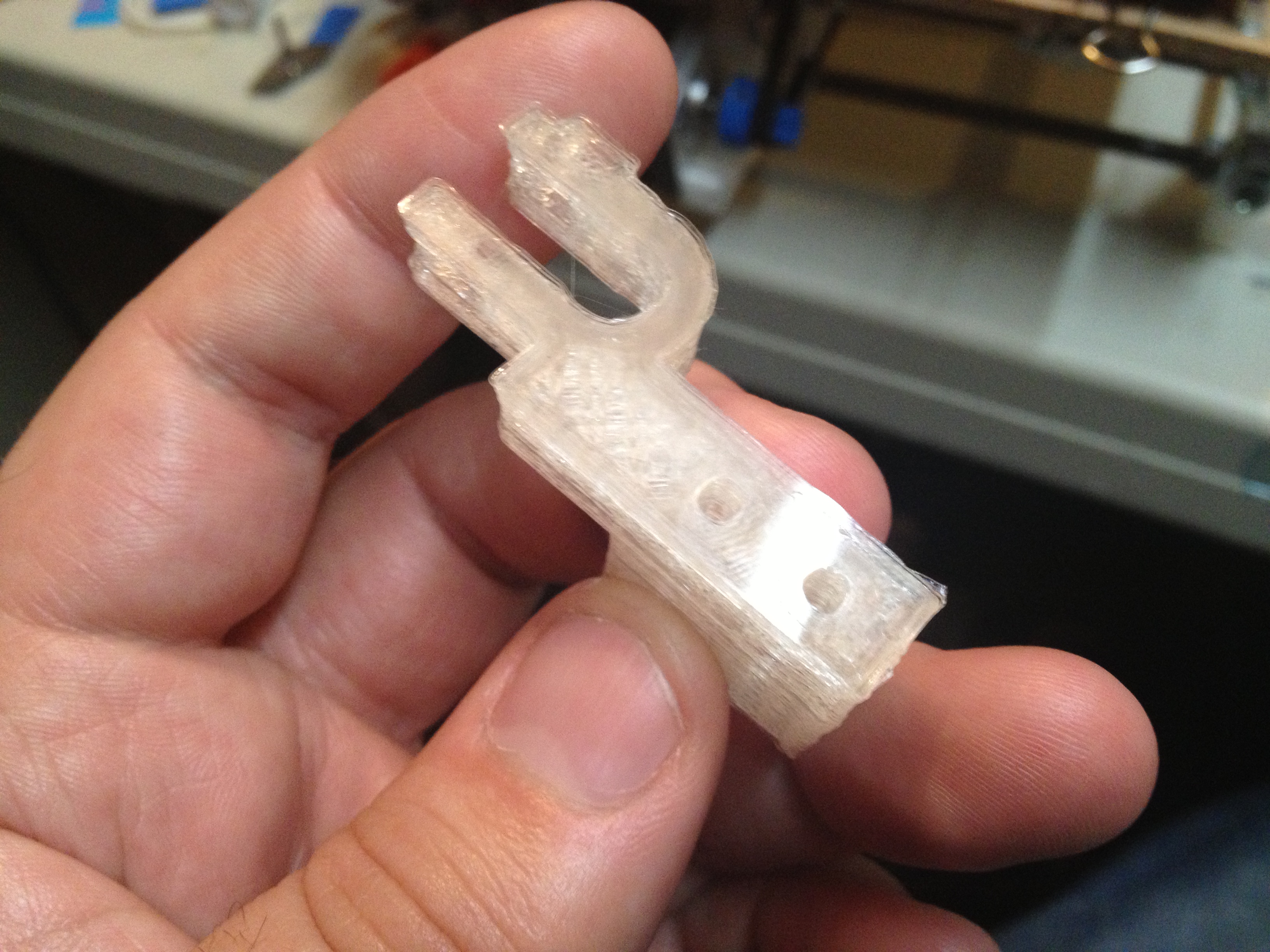
For the Z axis, I wanted to design a small opto-flag holder for Z (adapted from the endstop holder for Z). I set up the opto-endstop in a helping hands aligator clip to help measure what the piece should look like, and put the original z-endstop-holder (that I was adapting) on the X axis:
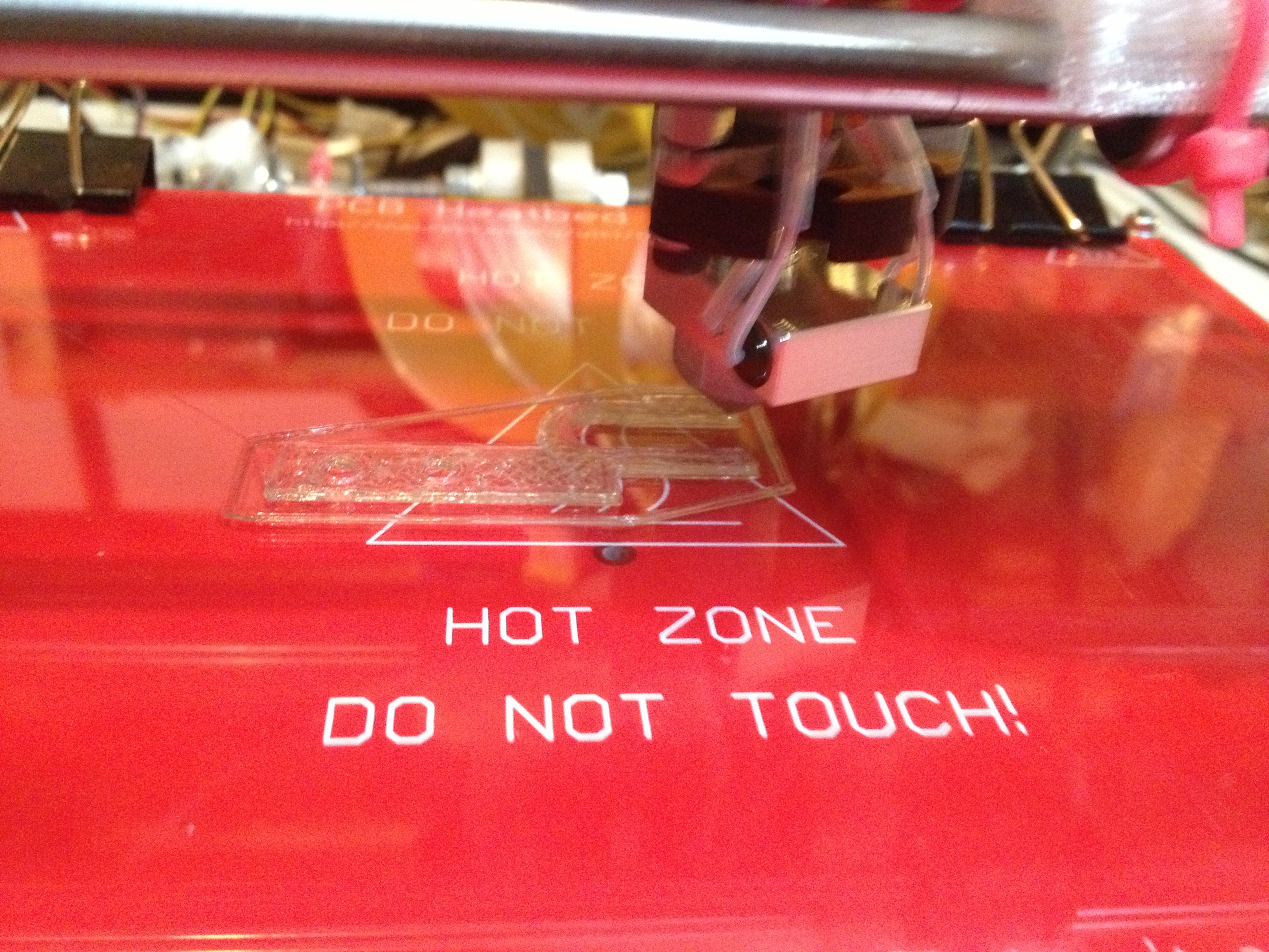
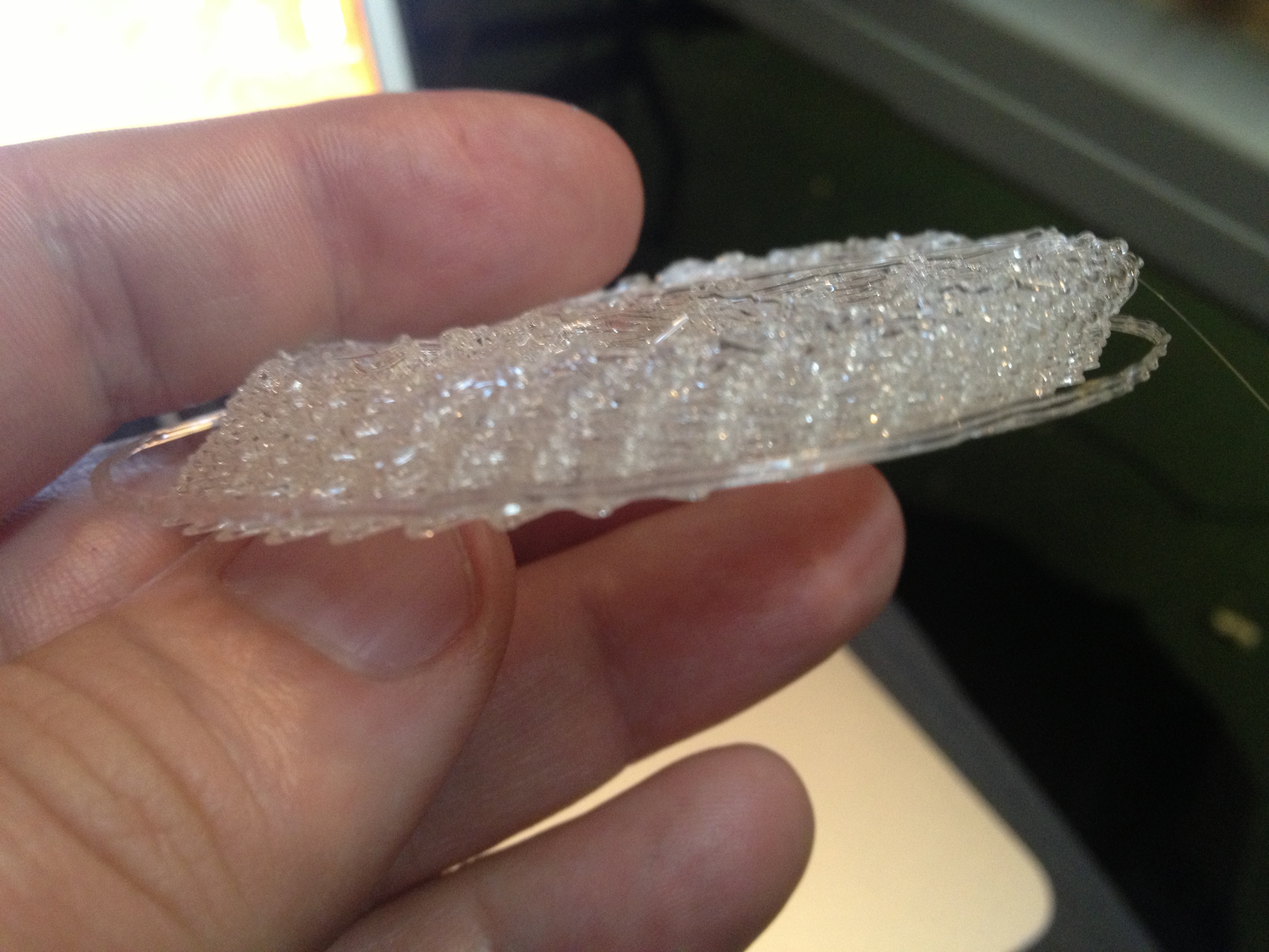
I measured it, designed what I wanted, and printed it on the Museum of Science’s RepRap (it printed its first enhancement part).
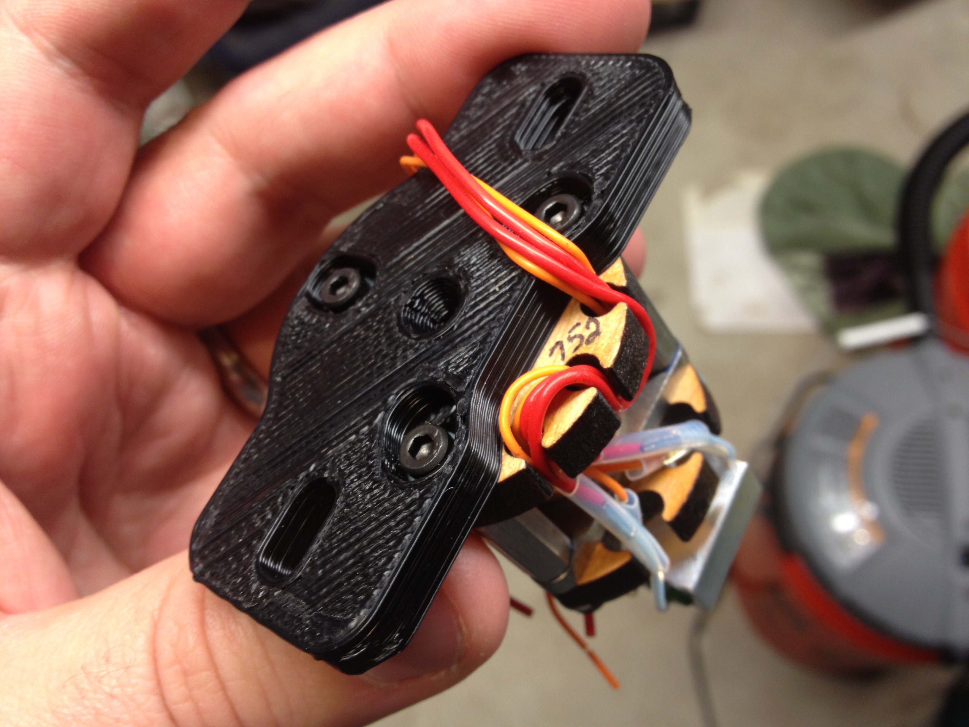
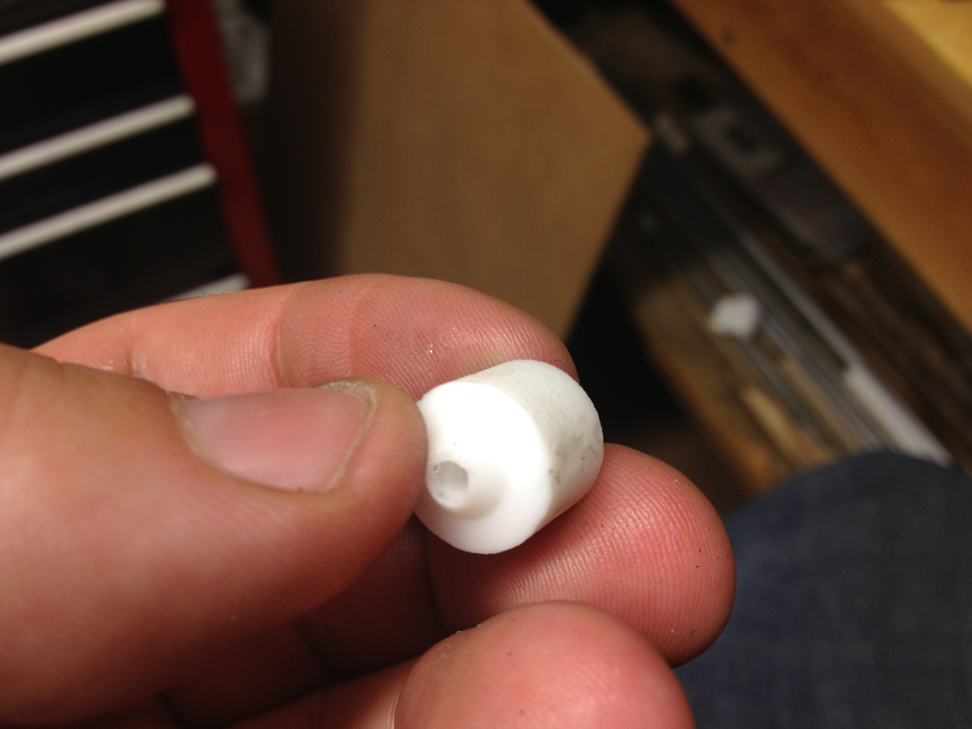
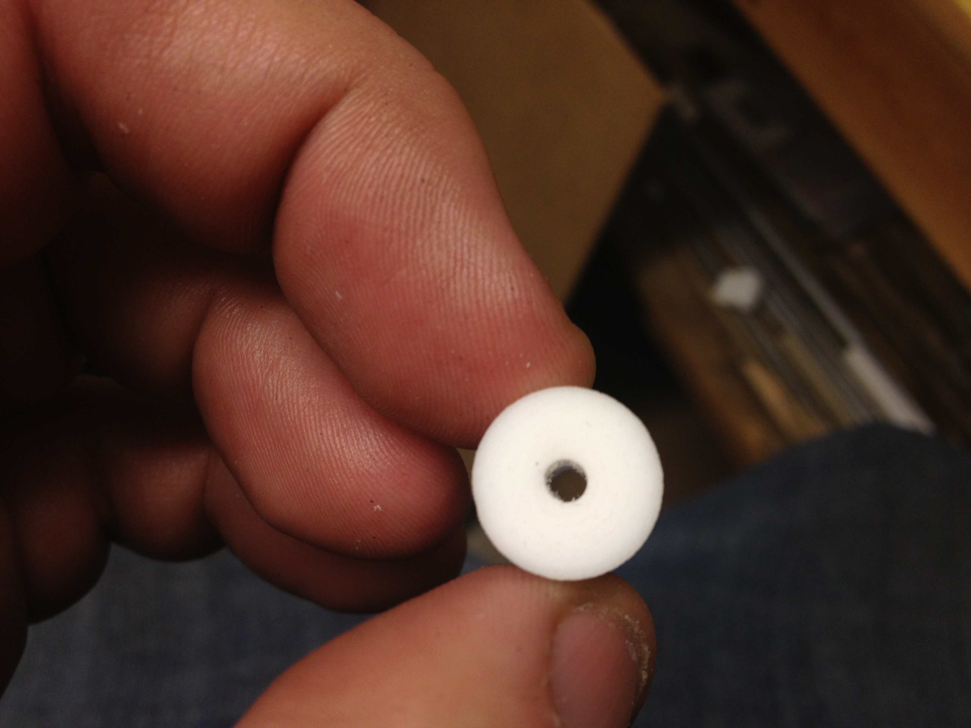
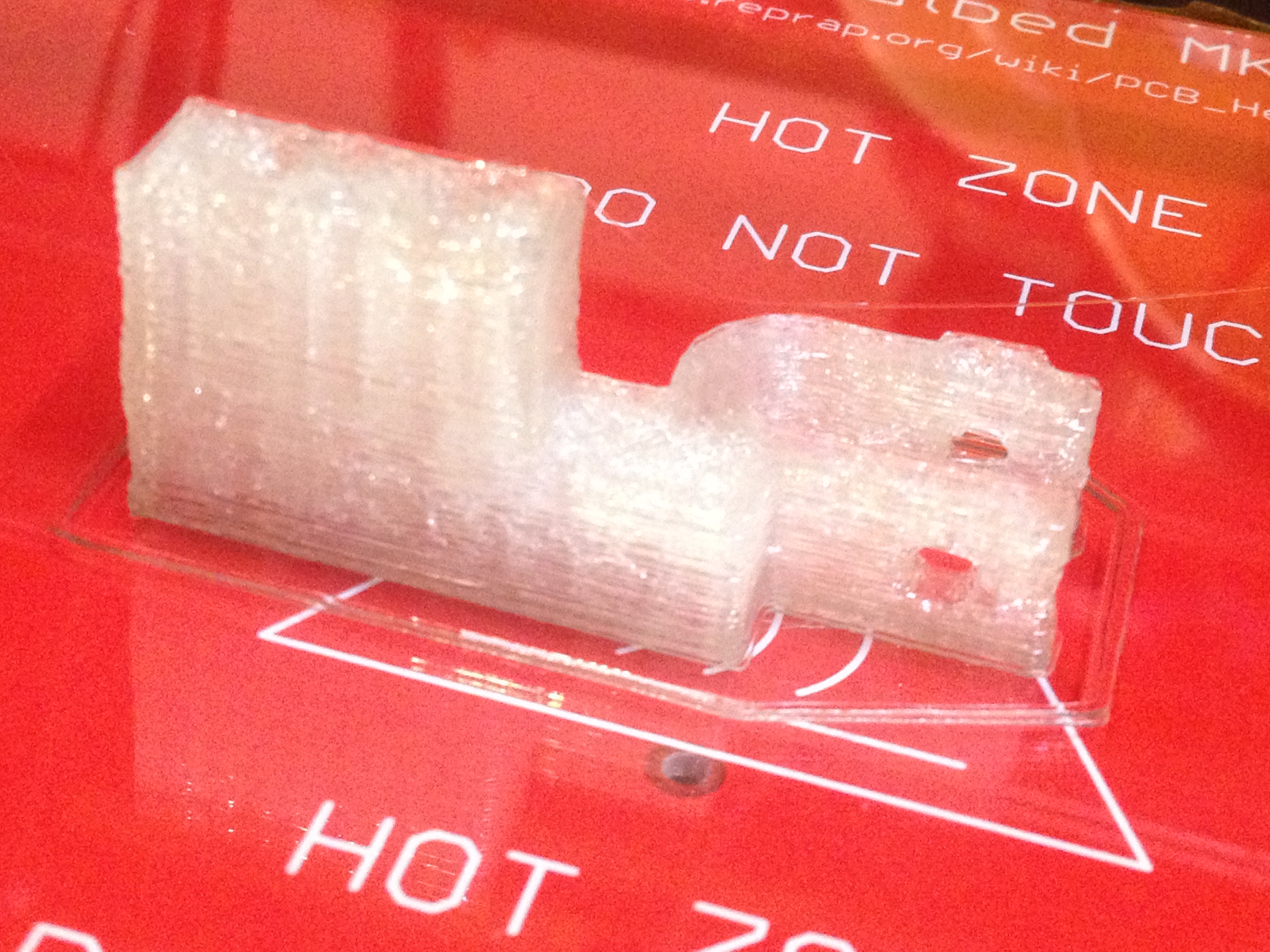
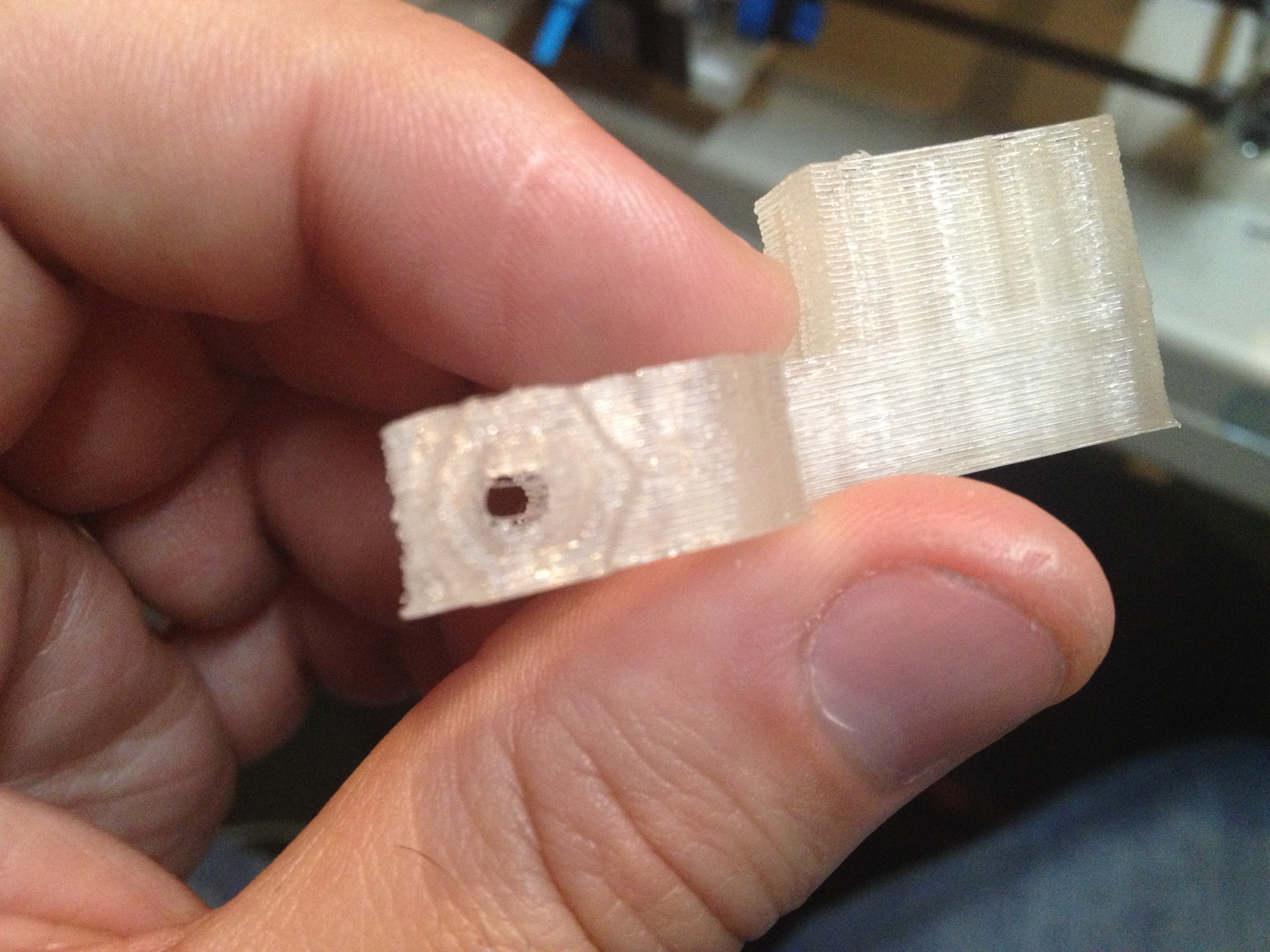
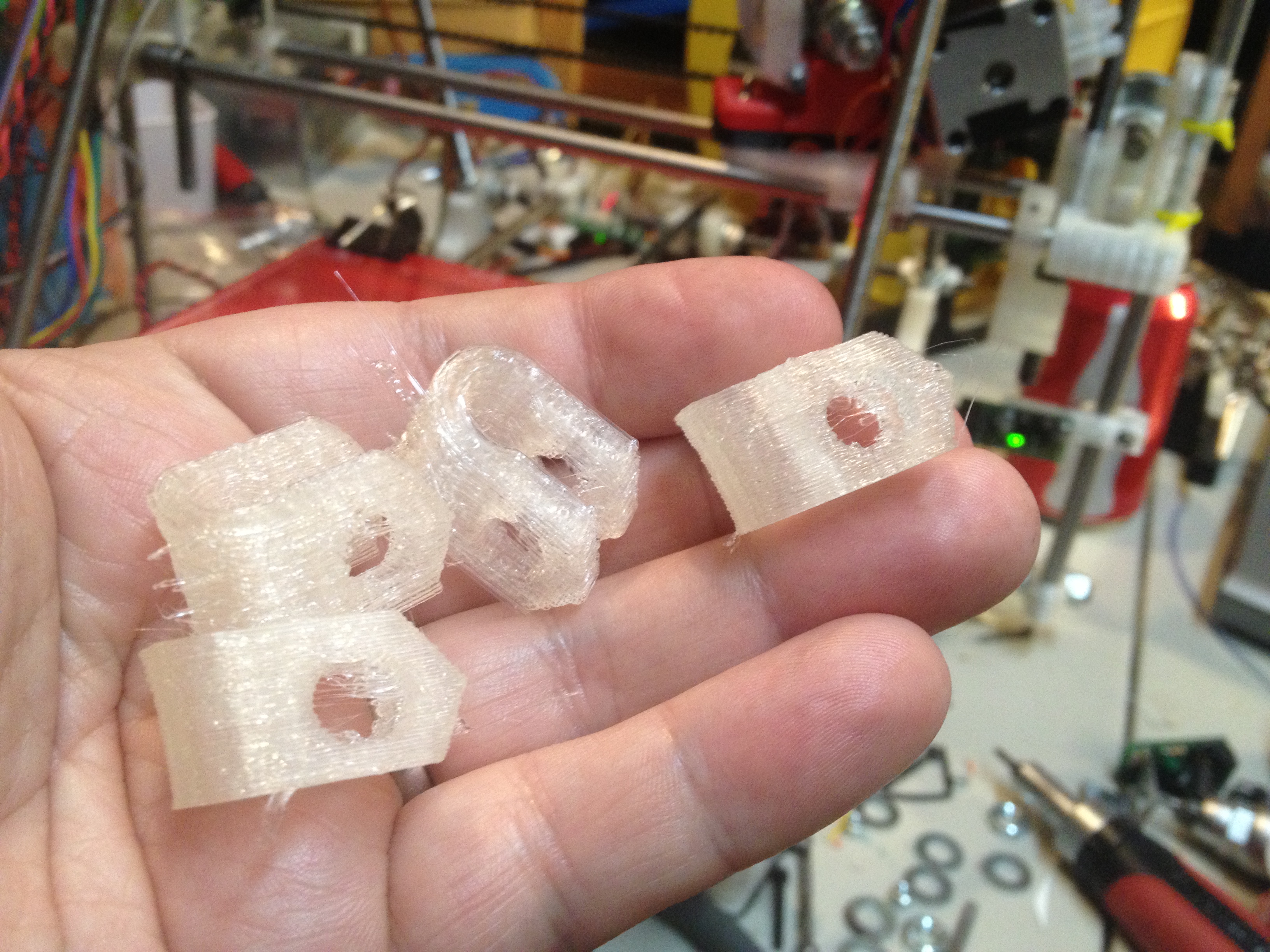
Here was the resulting part:
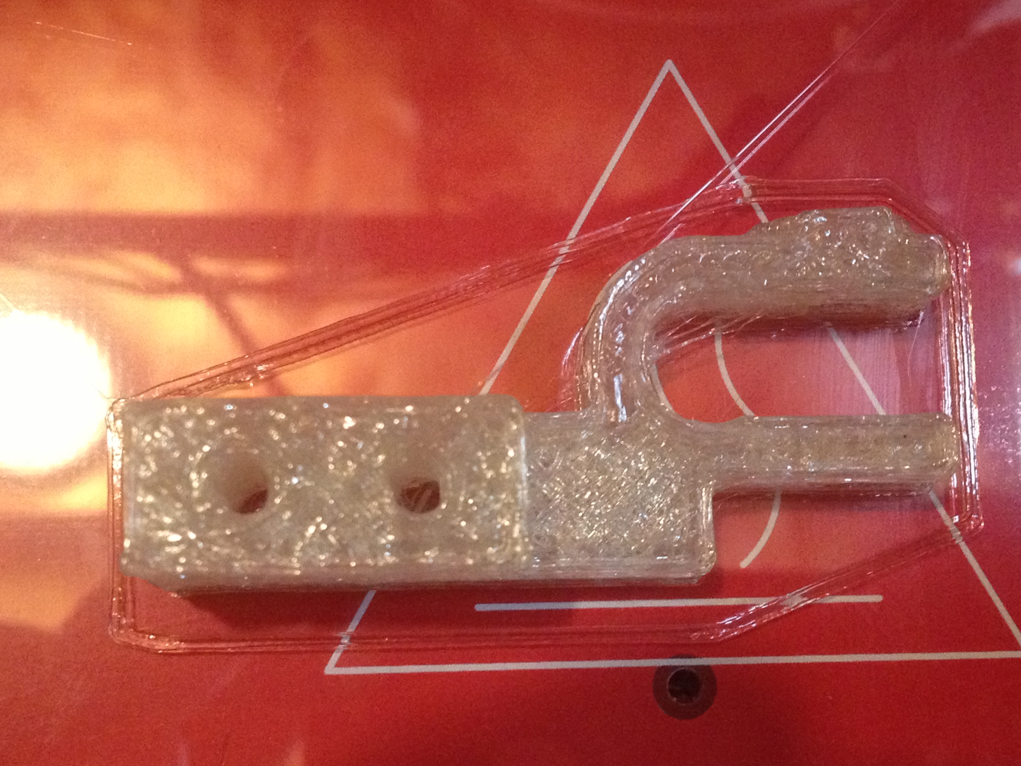
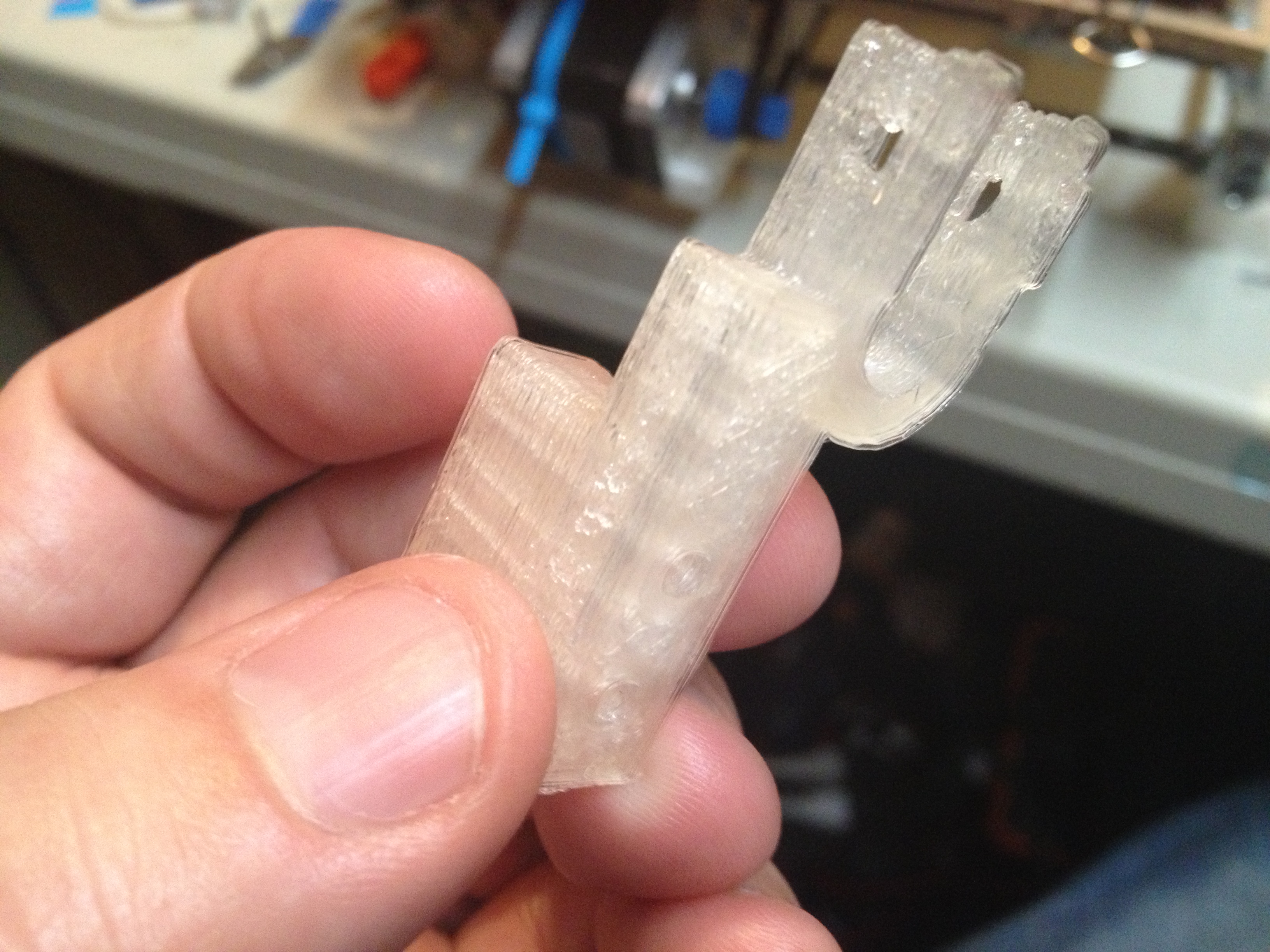
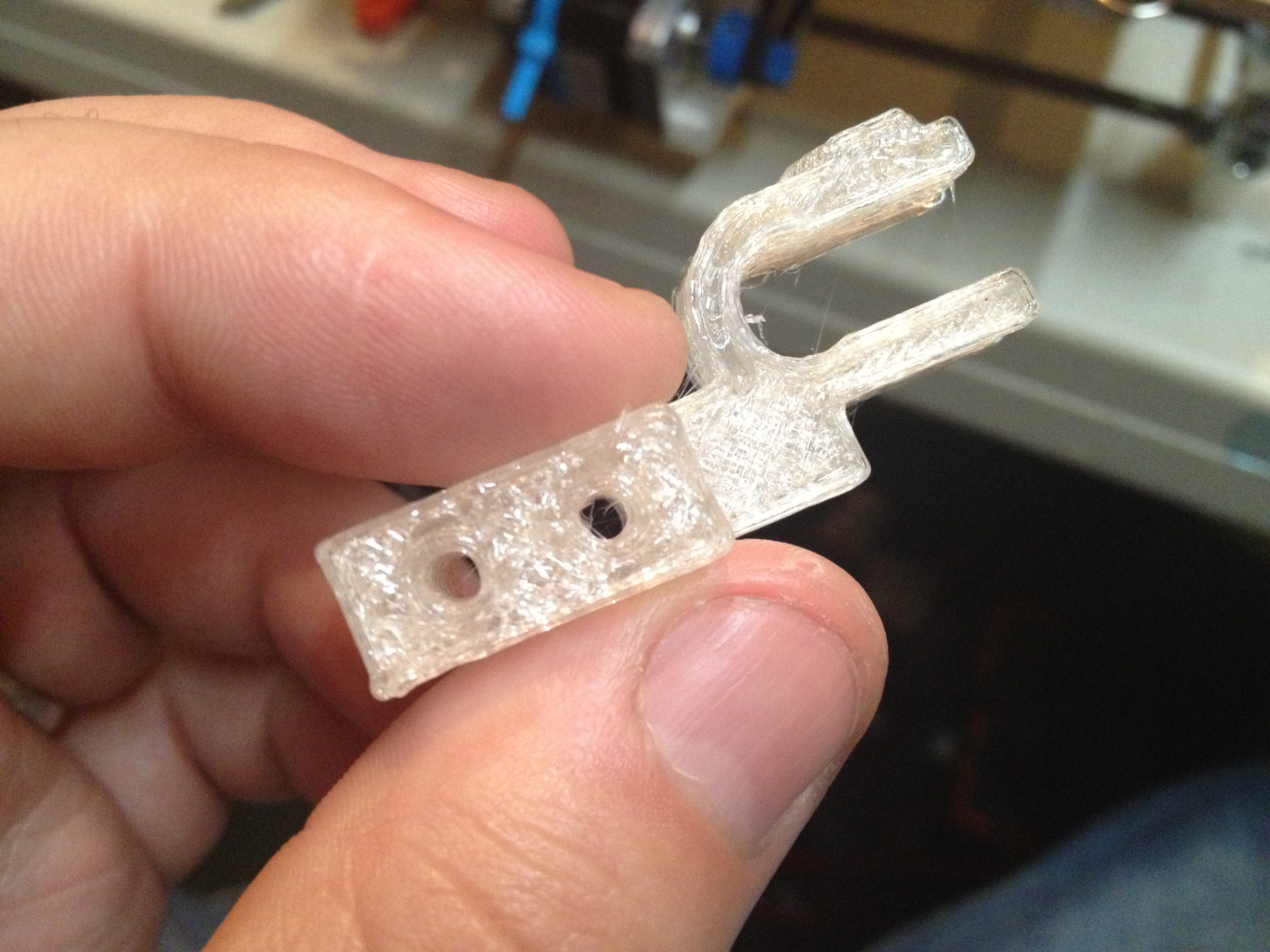
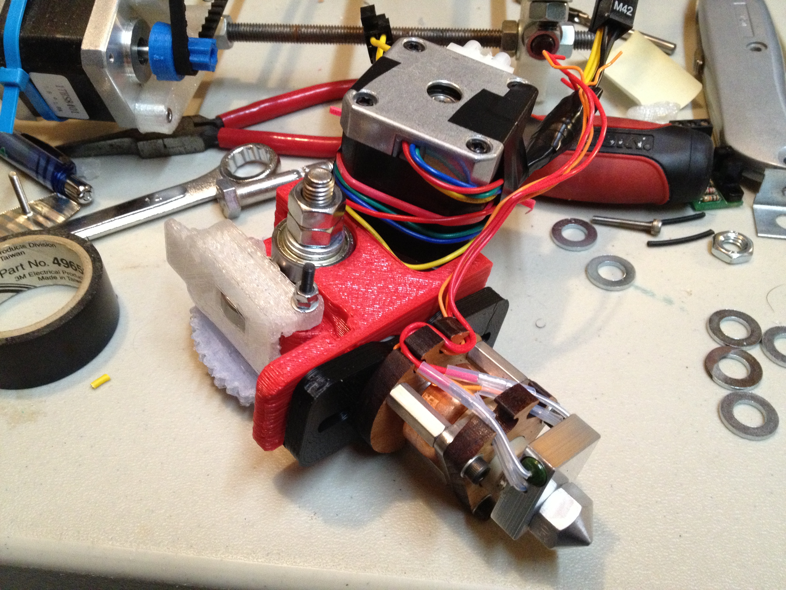
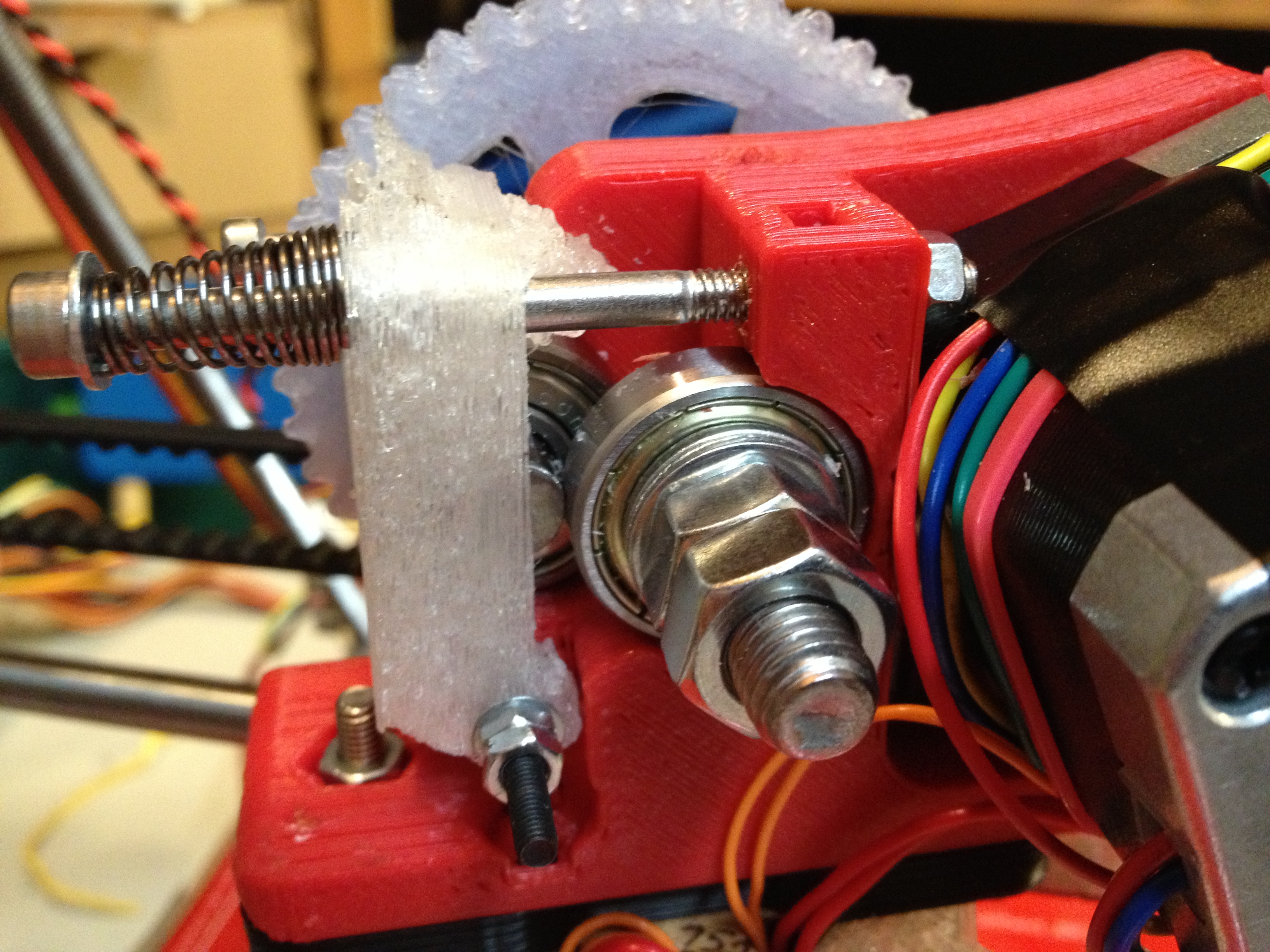
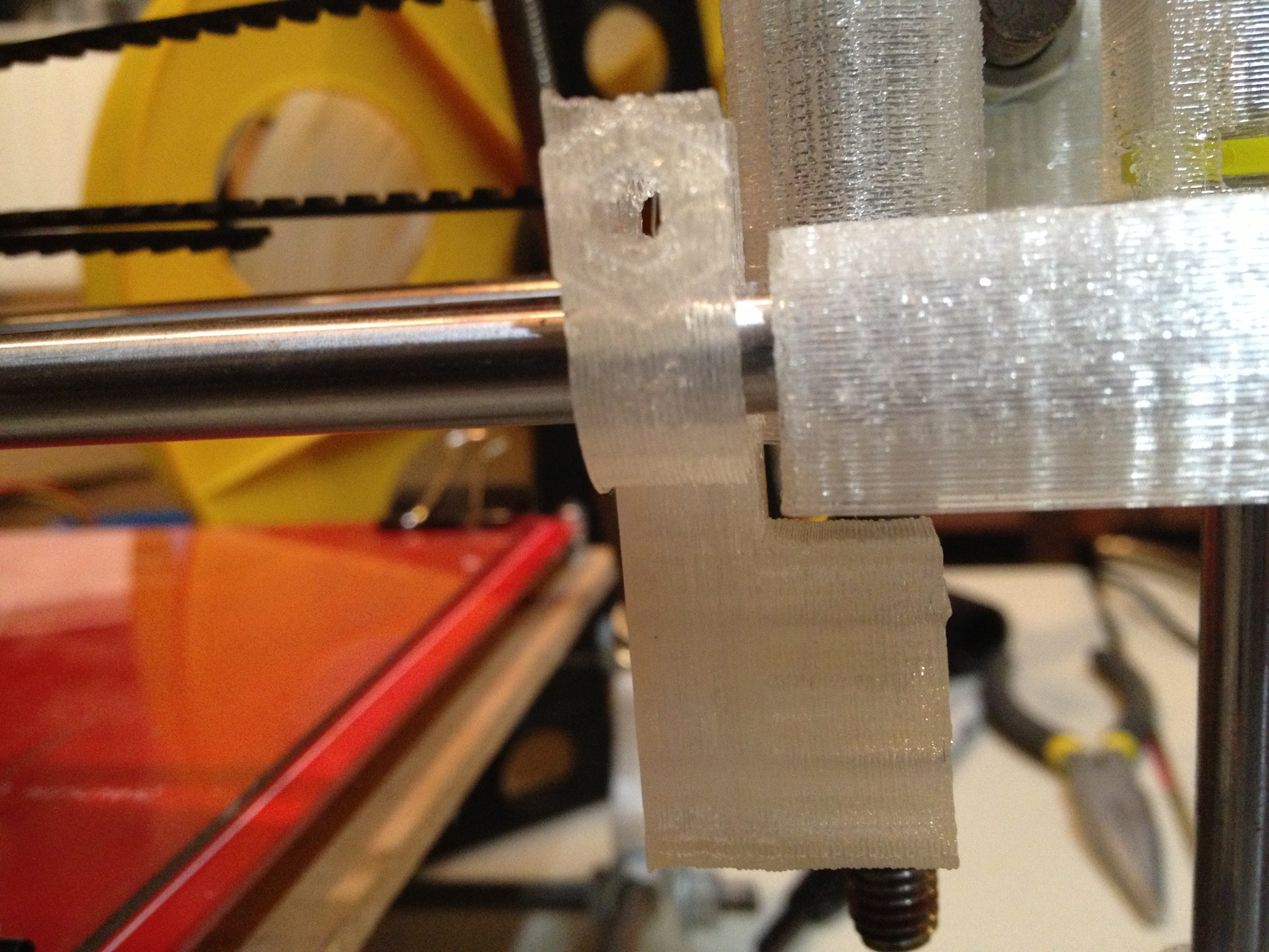
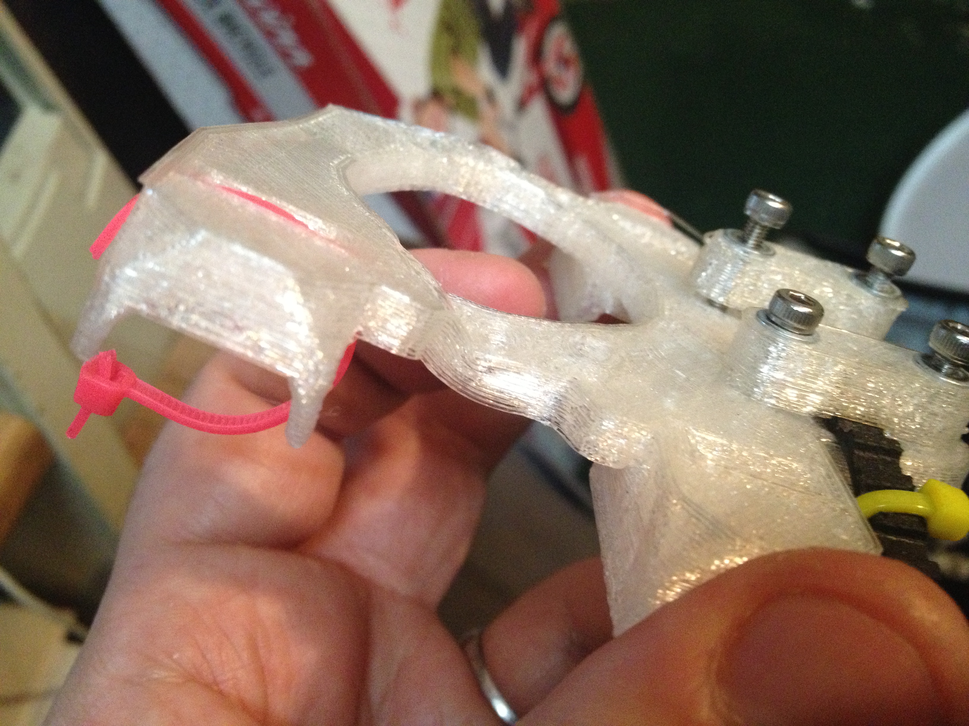
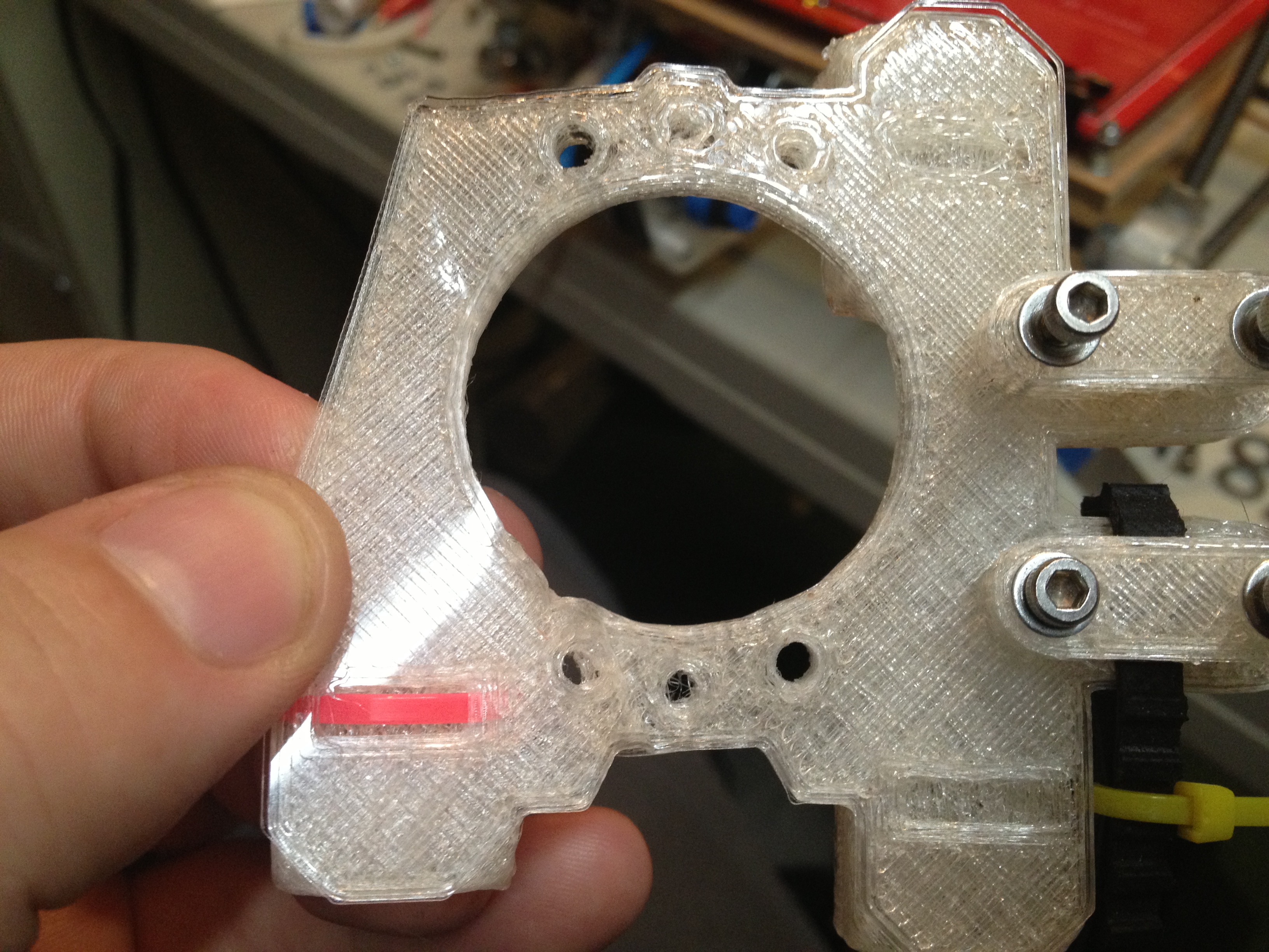
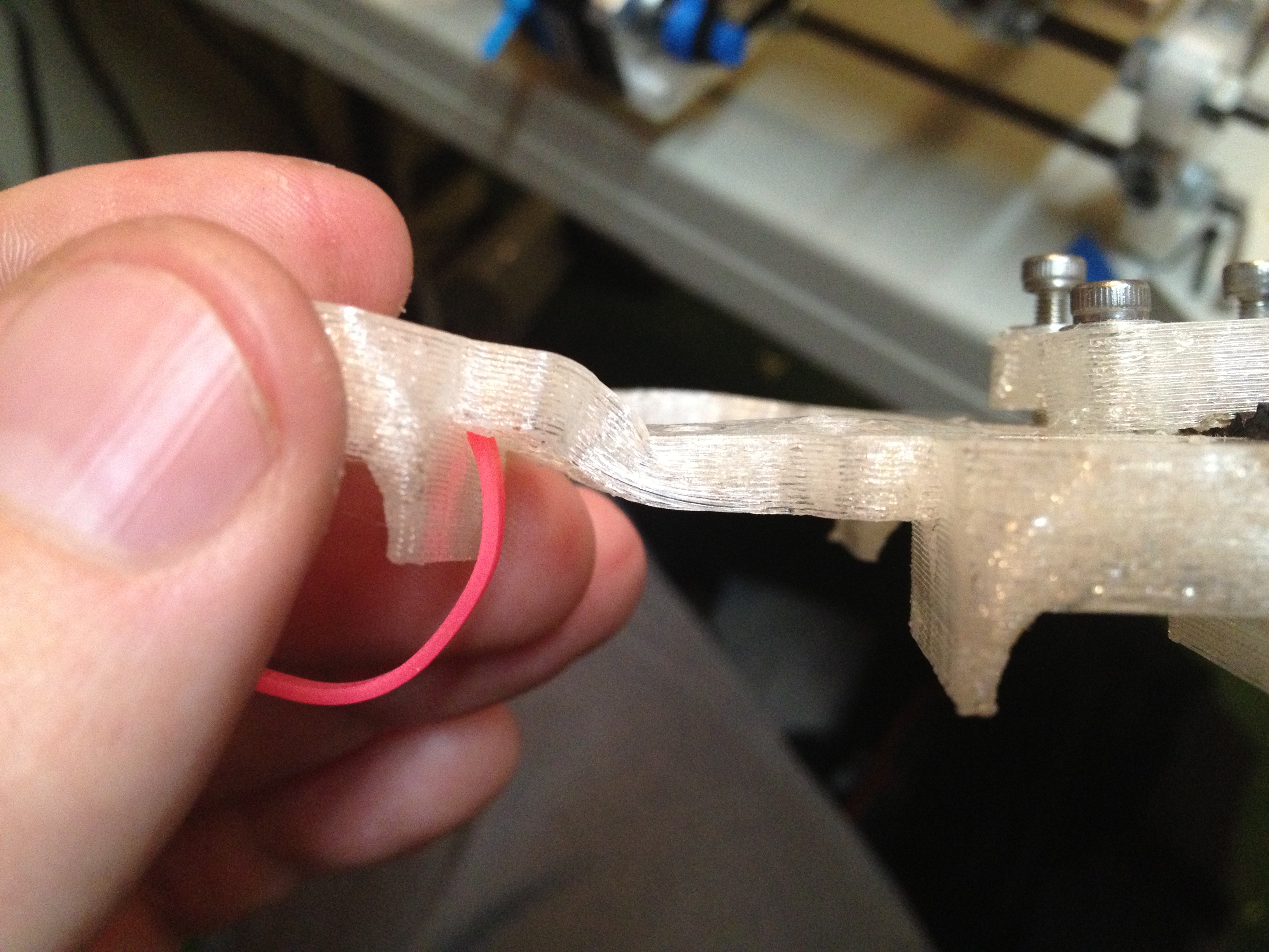
..and here is the new piece on the x-axis where the old original piece I adapted from had been:
This next video was horribly truncated (probably because my phone ran out of space or battery life) and I usually wouldn’t include it, but it feels a bit historic so I’ll include it for the 24 seconds that it lasts for:
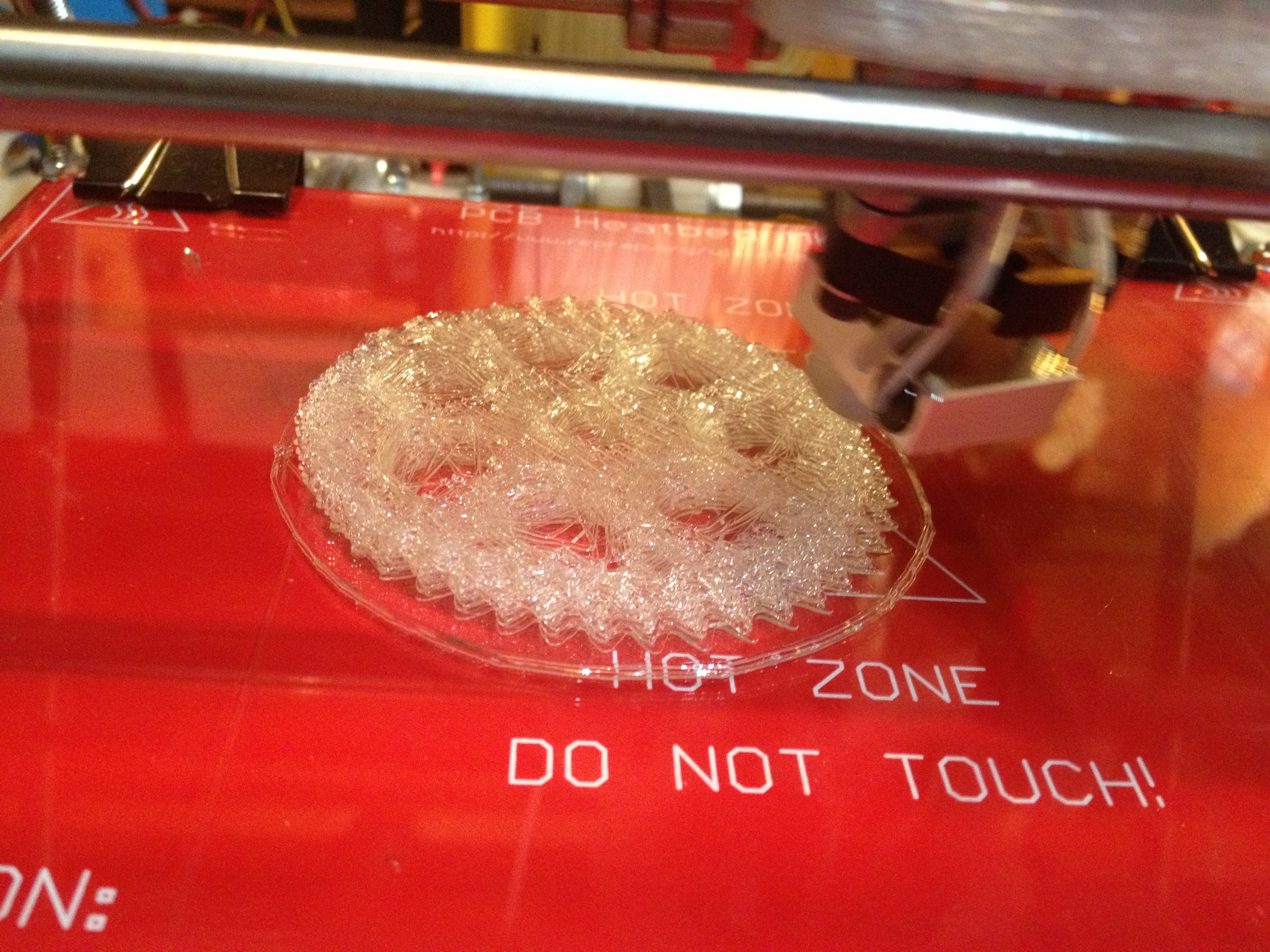
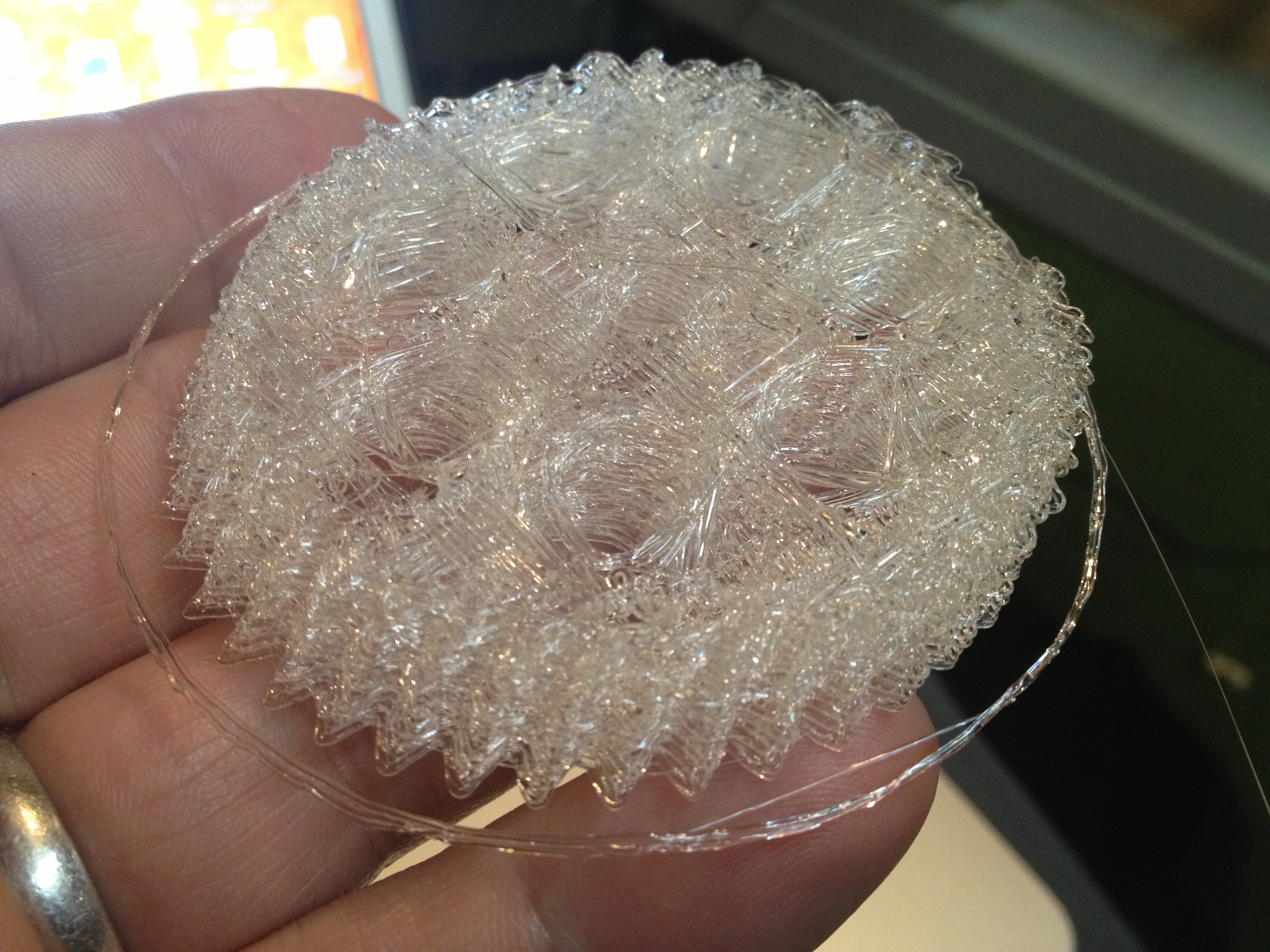
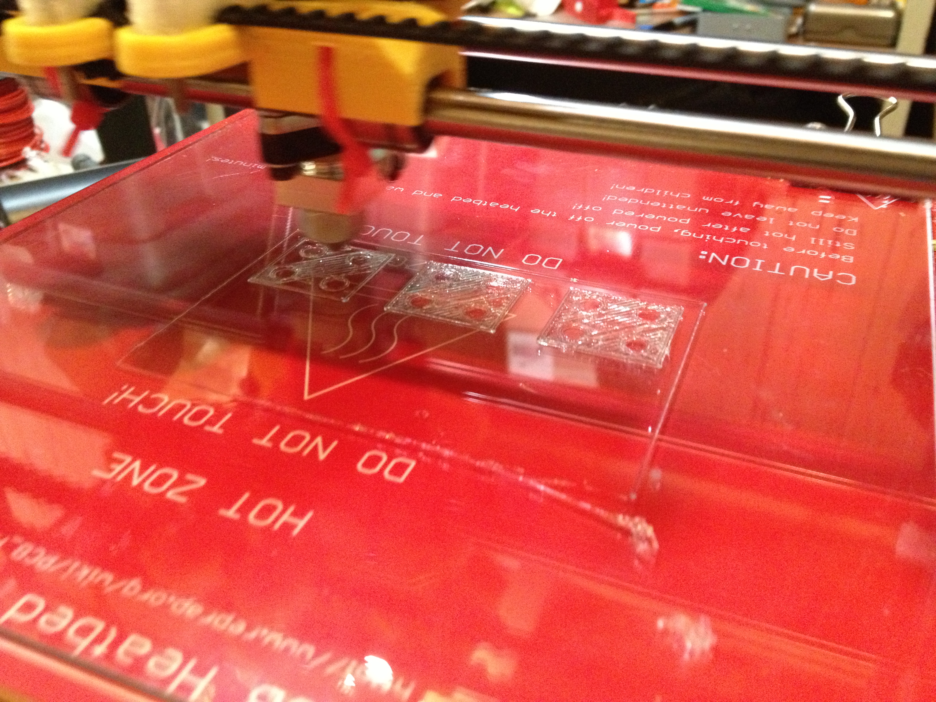
I had more work to do on the opto-flag holder (more on that later), but first I wanted to make a proper filament spool holder. I tried printing 4 of these new-style rod holders (I’d later realize I needed two of these and two of the old style), but then I ran into the new problem that my prints were slanting on X and Y (not individual skips, but full slants for every layer):
I guess I tried printing something else hoping the problem would go away, because the next picture I have is of that effect getting far far worse:
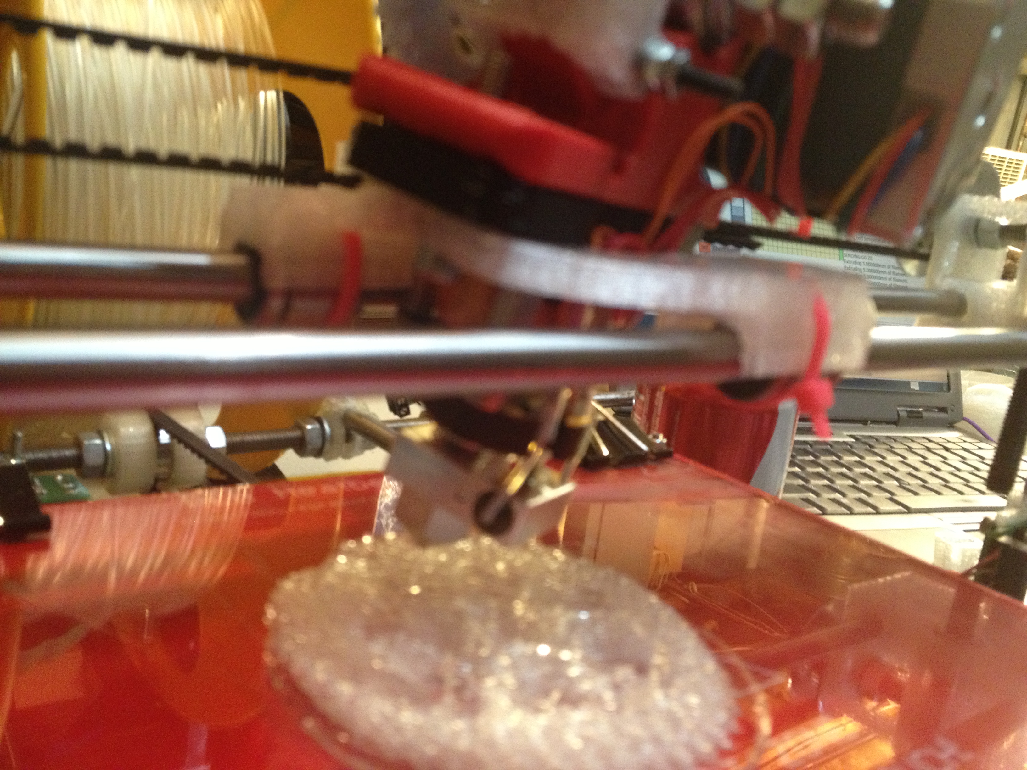
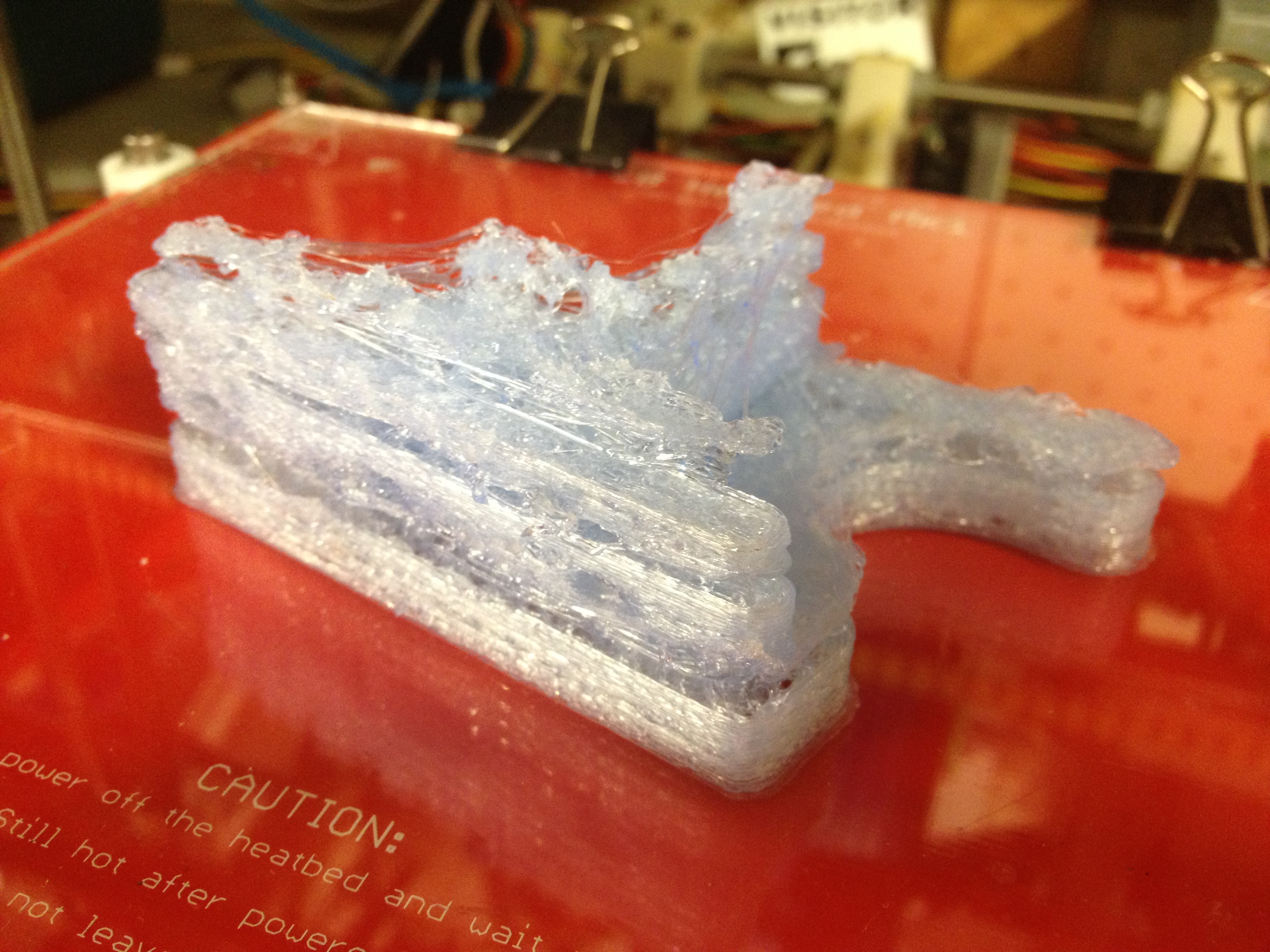
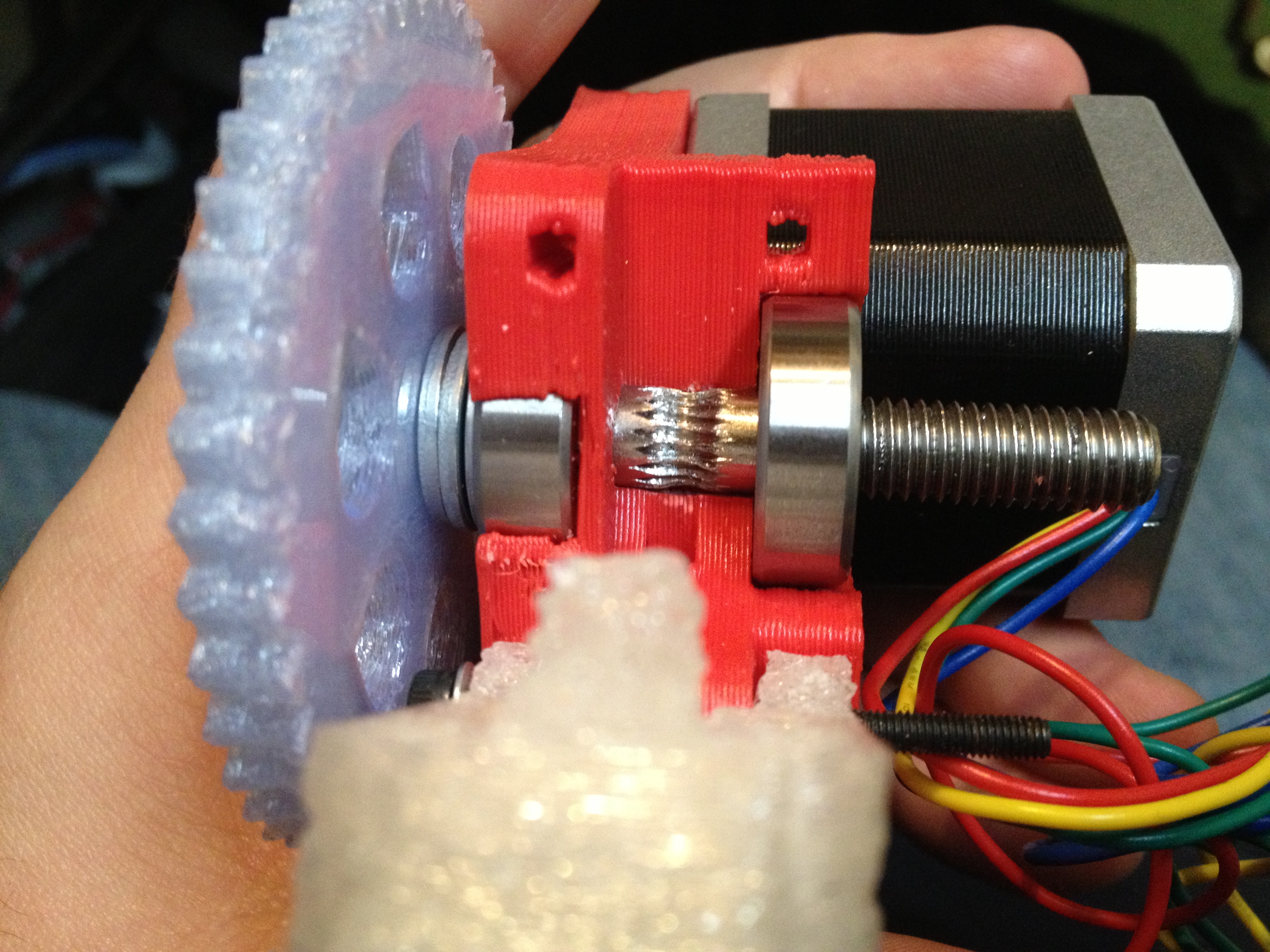
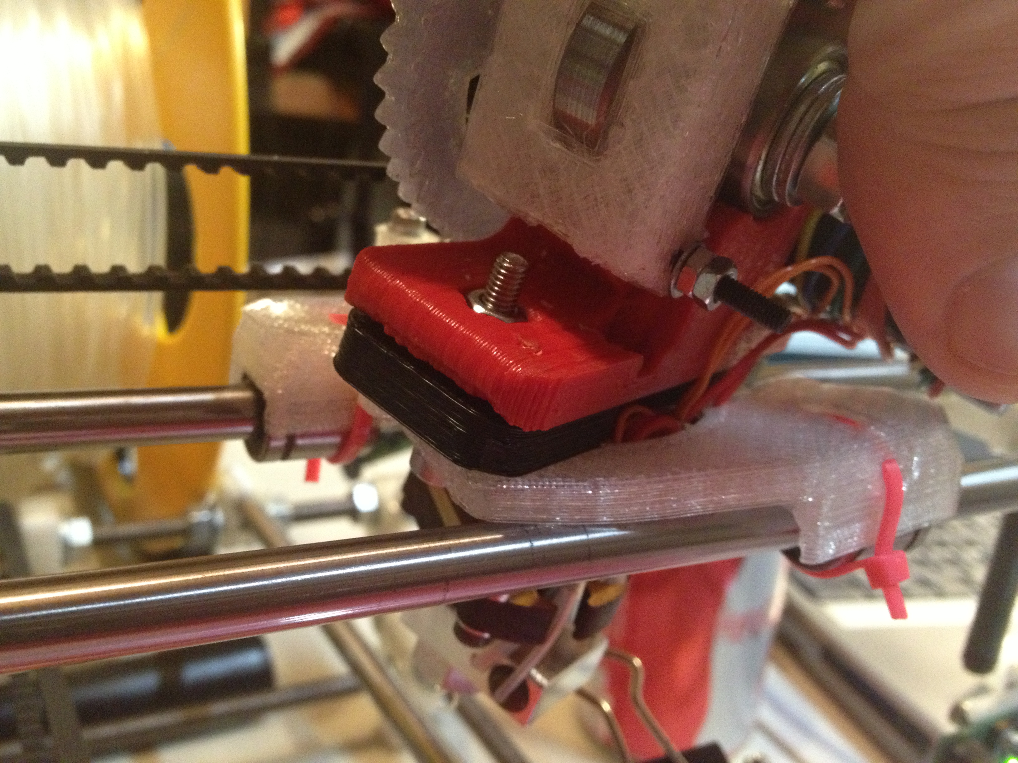
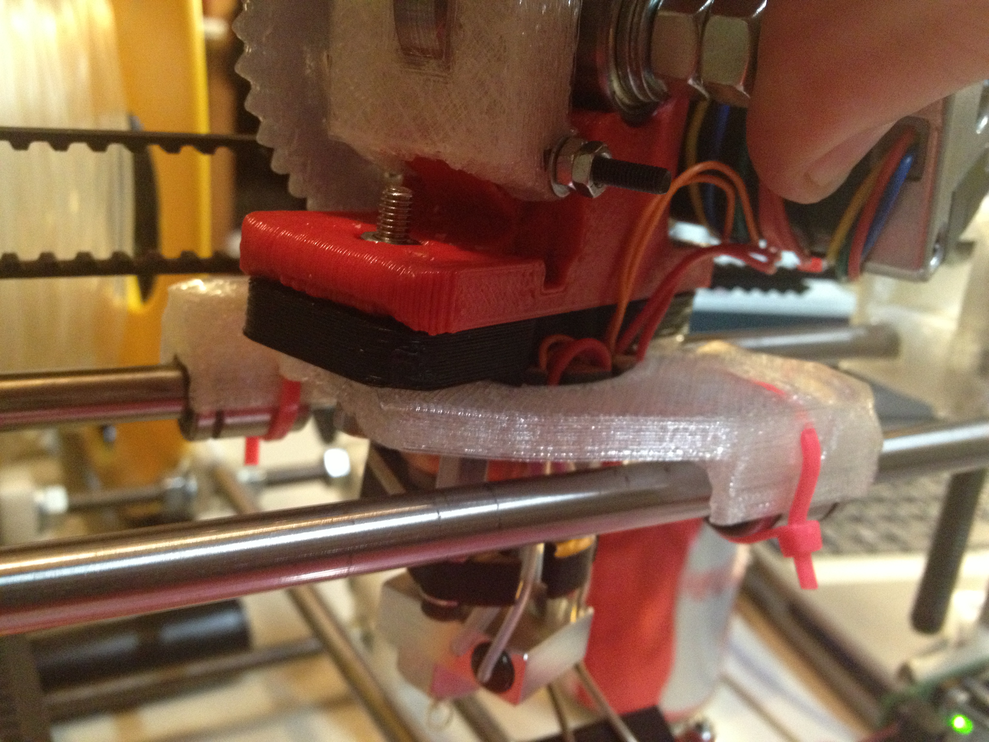
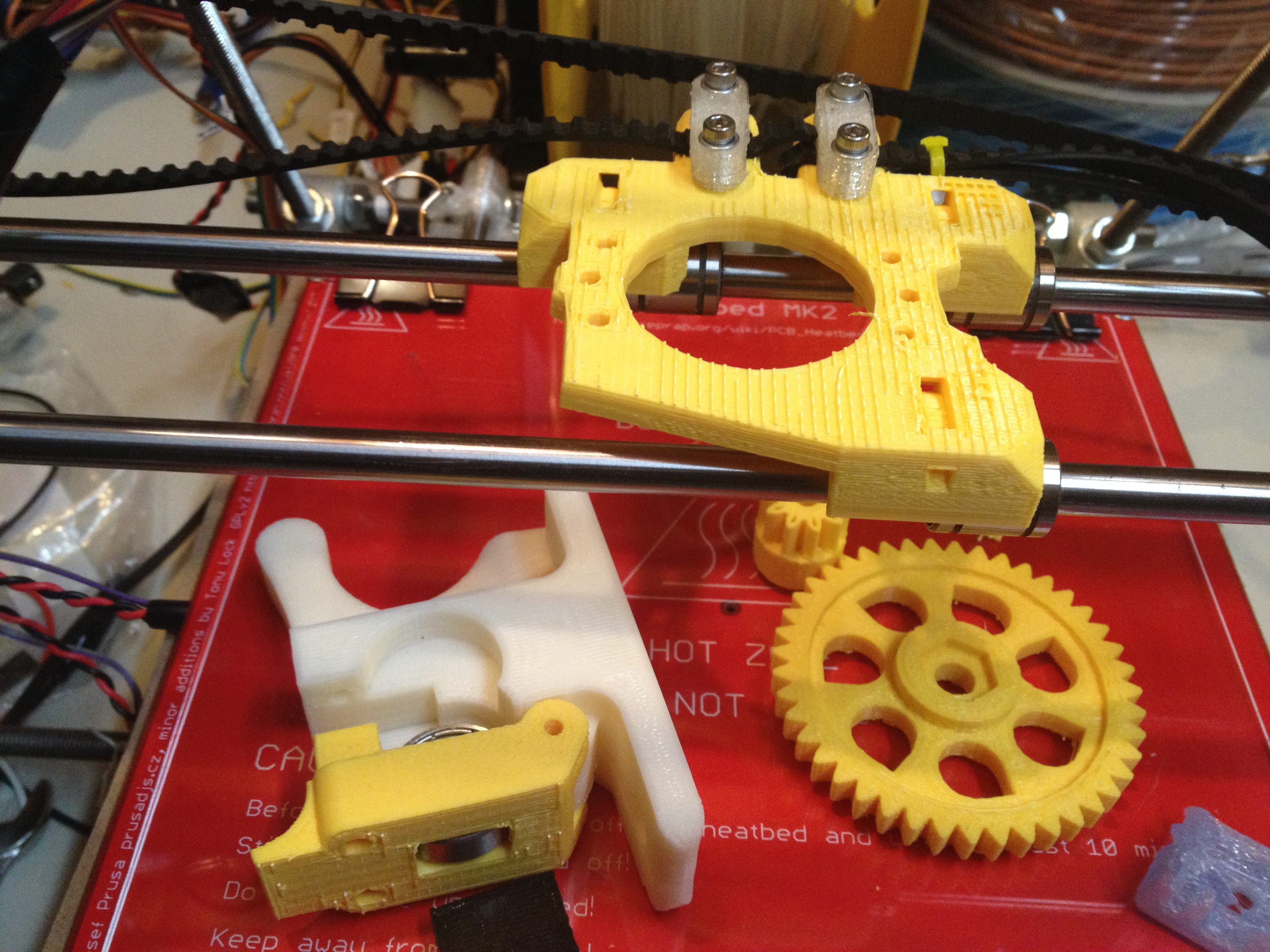
It was at this point that I started to suspect that my X-carriage had just melted…
Yup.. Your x-carriage should NOT do this:
Here was that gear attempt that had failed because the nozzle was lifting up and back left:
What’s the lesson to be learned here? Don’t make carriages or extruders out of PLA.
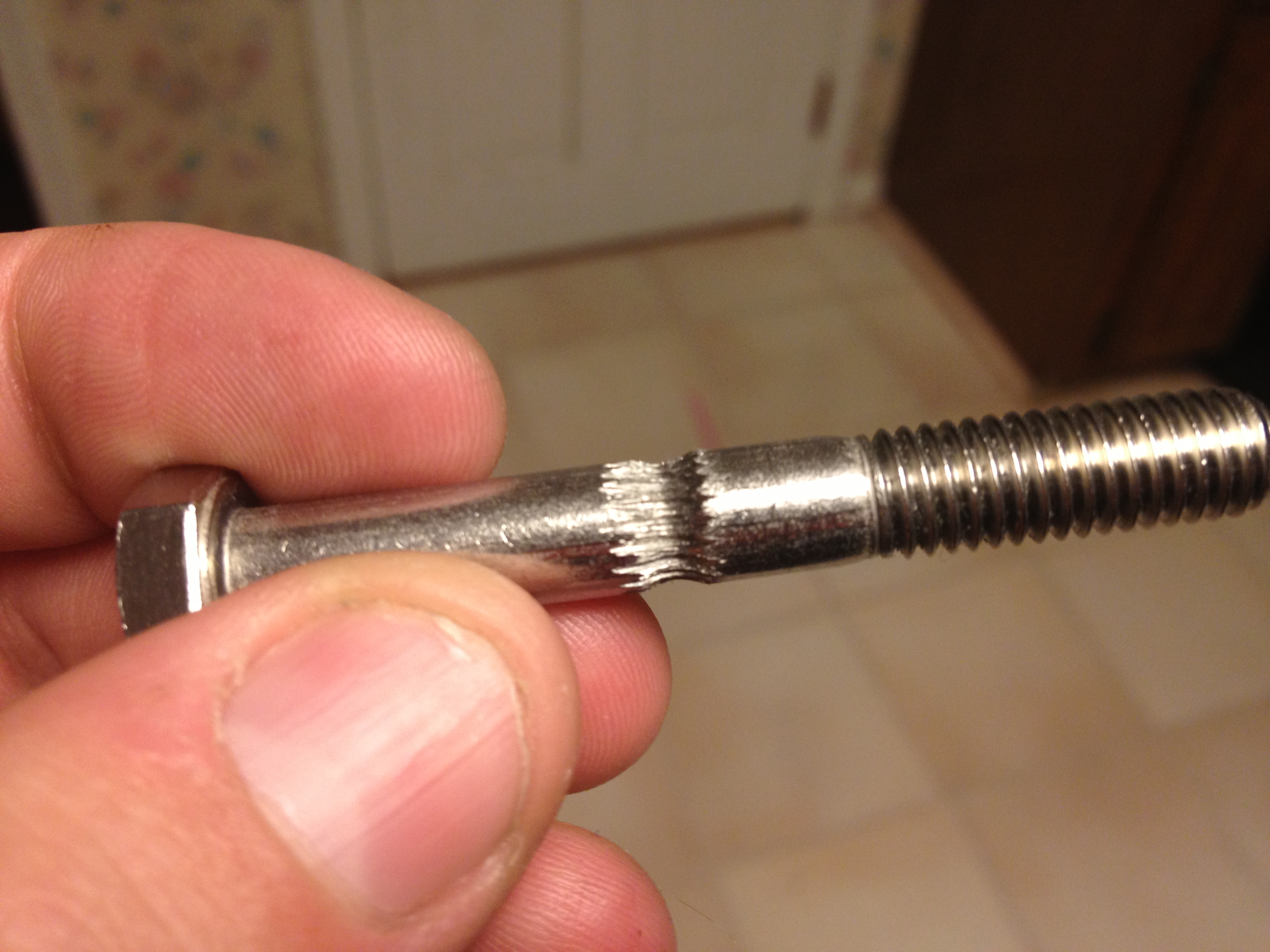
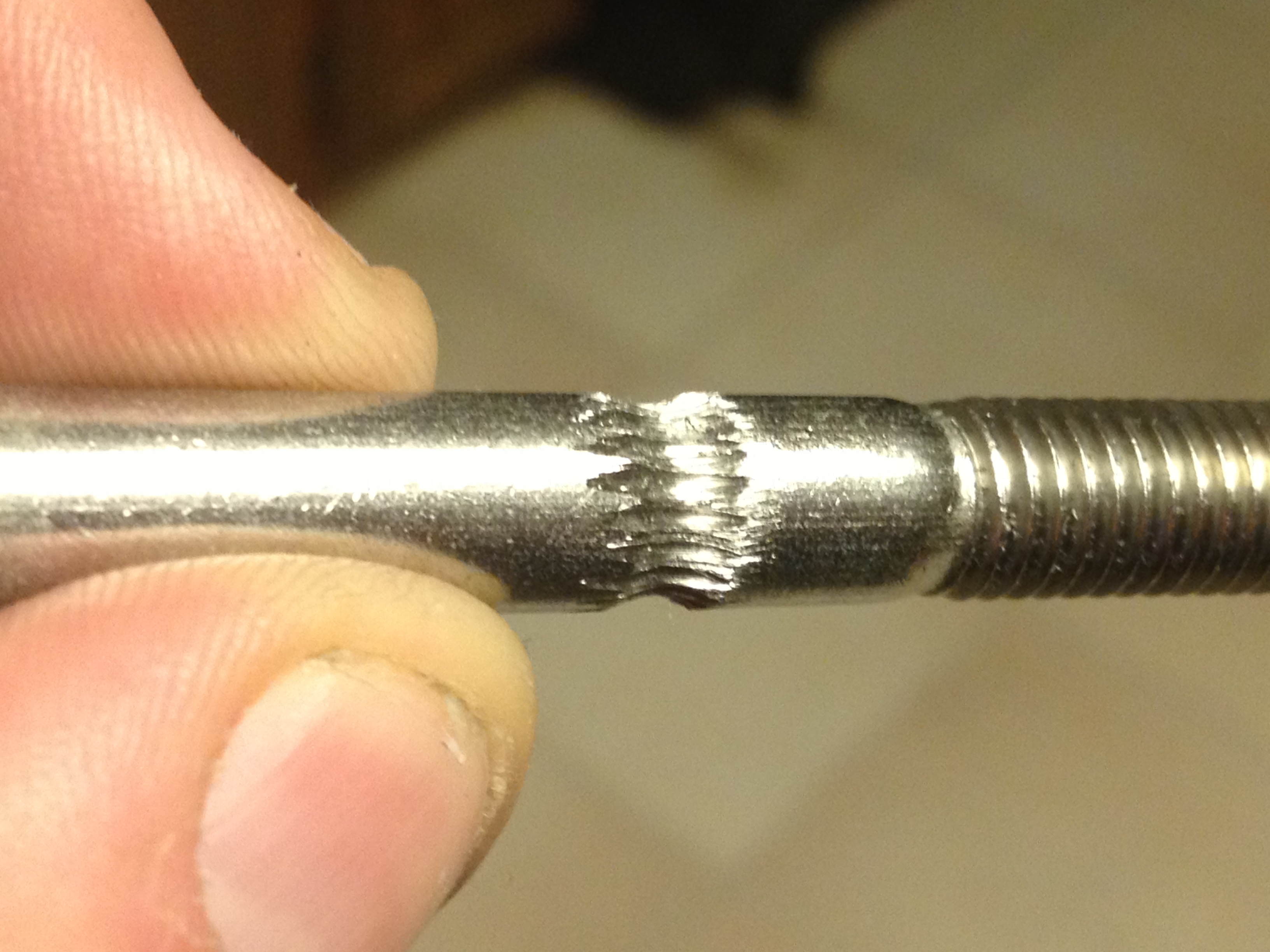
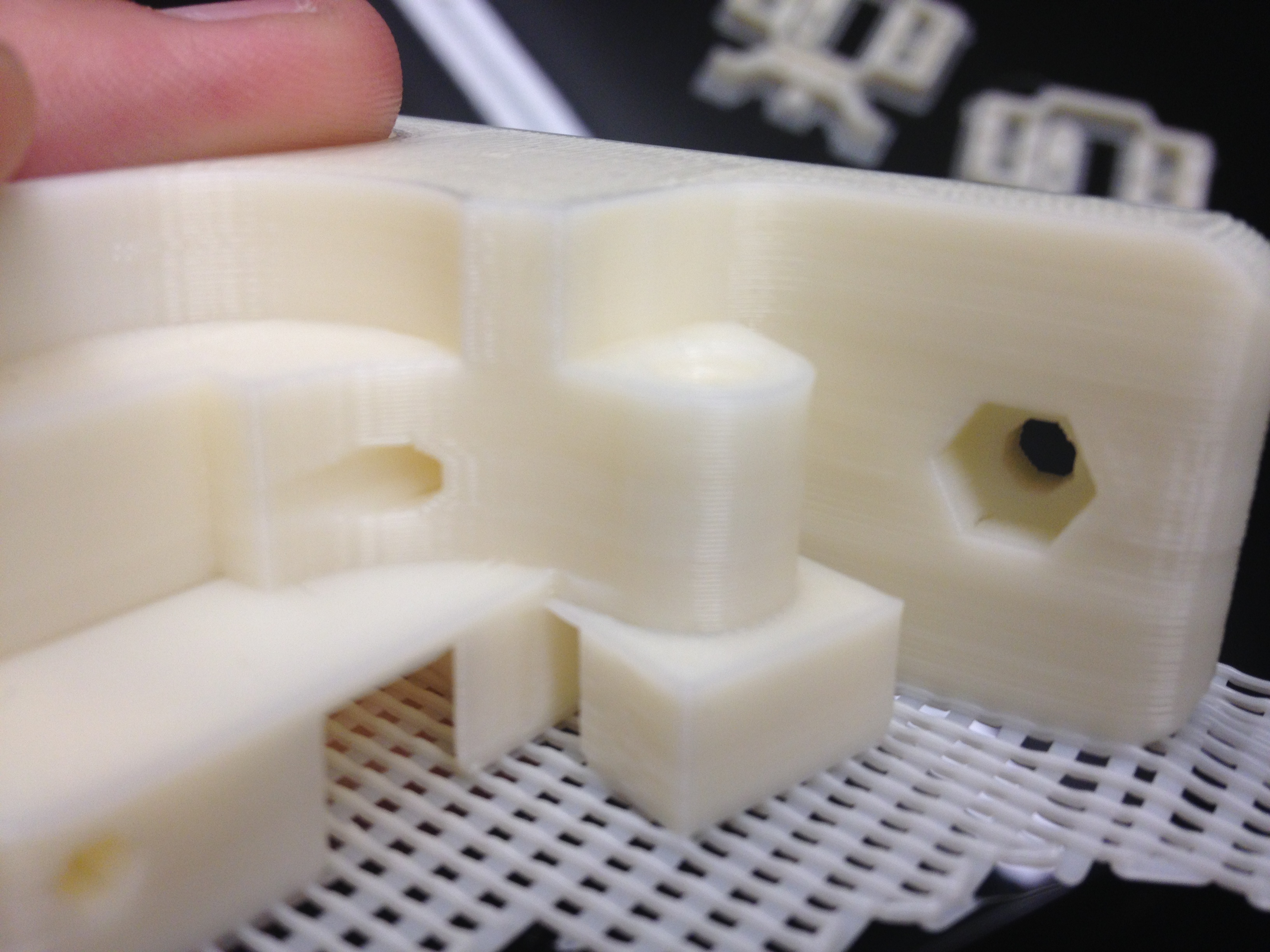
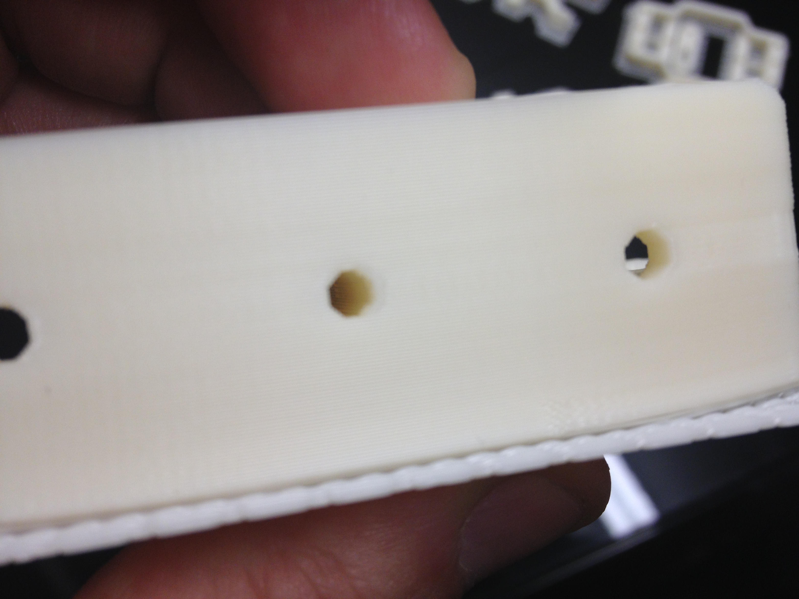
Here are some more pictures of the melted carriage:
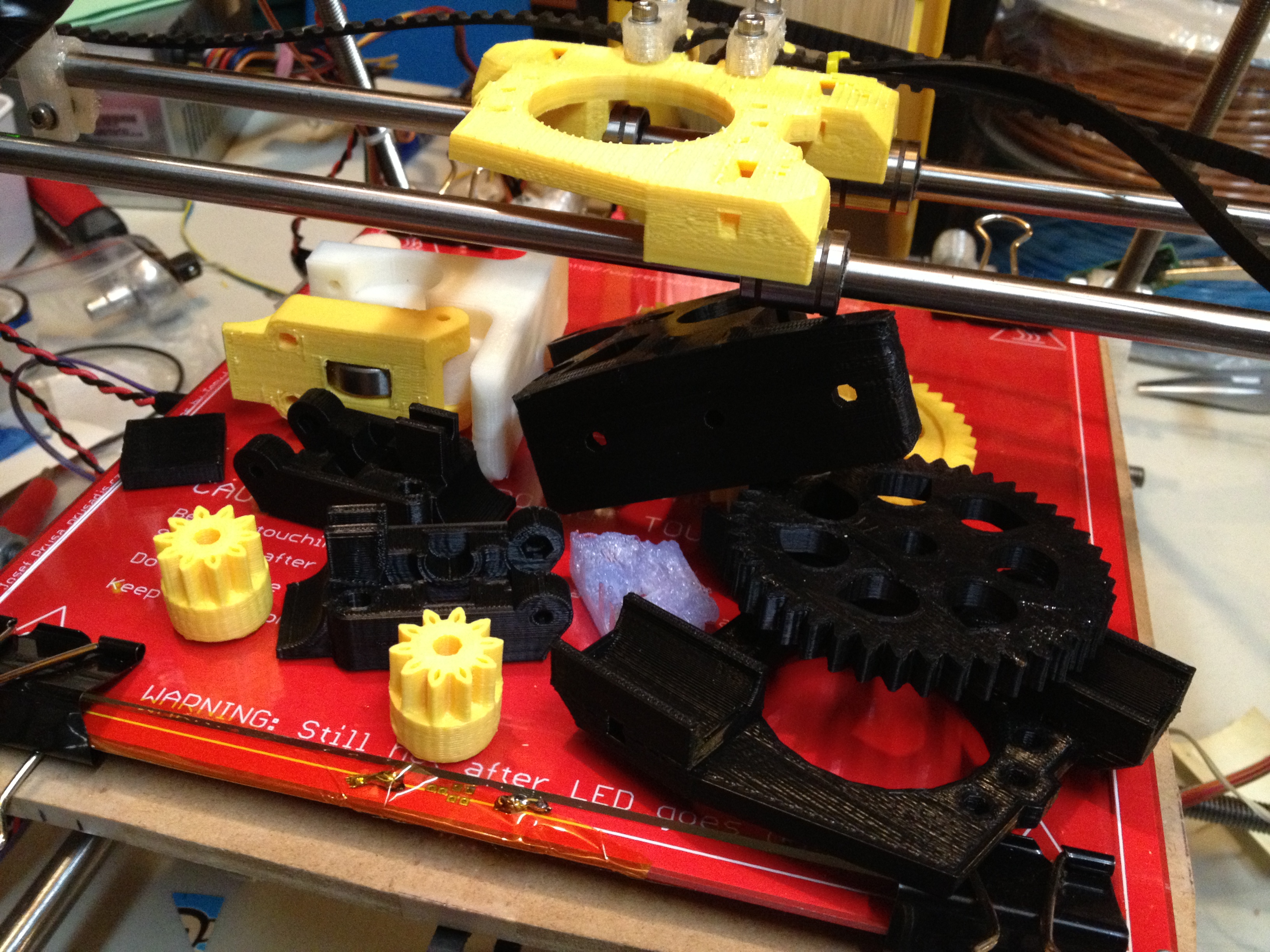
I printed a carriage out of ABS on a Makerbot Replicator that I’d borrowed for something else. I wasn’t about to muck with mixing ABS and PLA in a nozzle of my own RepRap (or the Museum of Science’s RepRap) at this point:
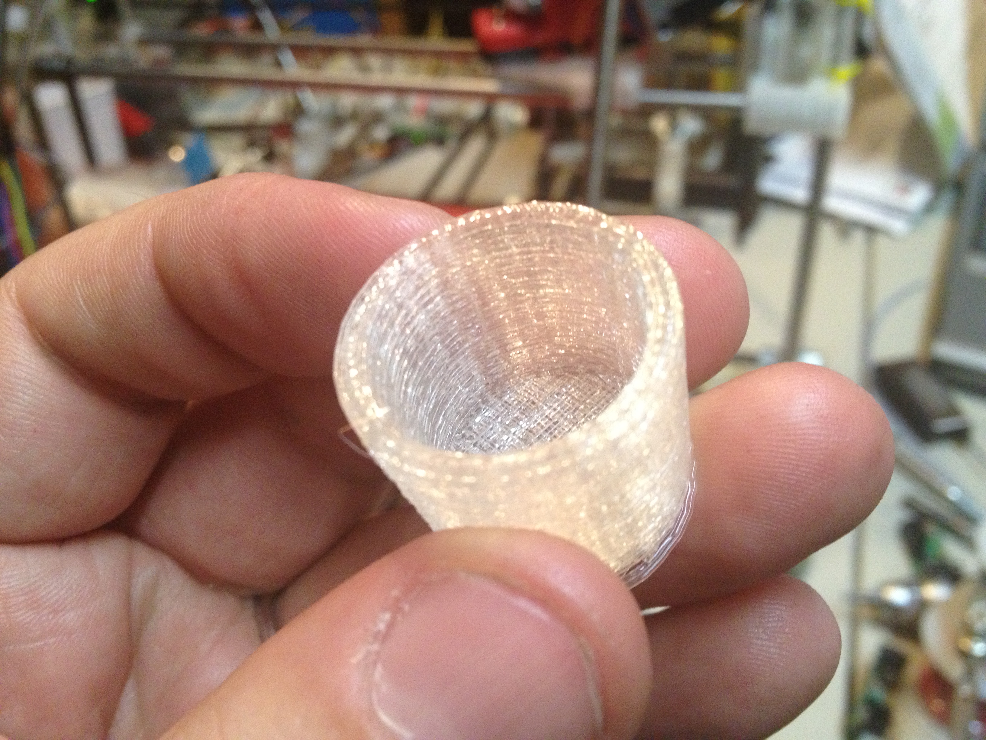
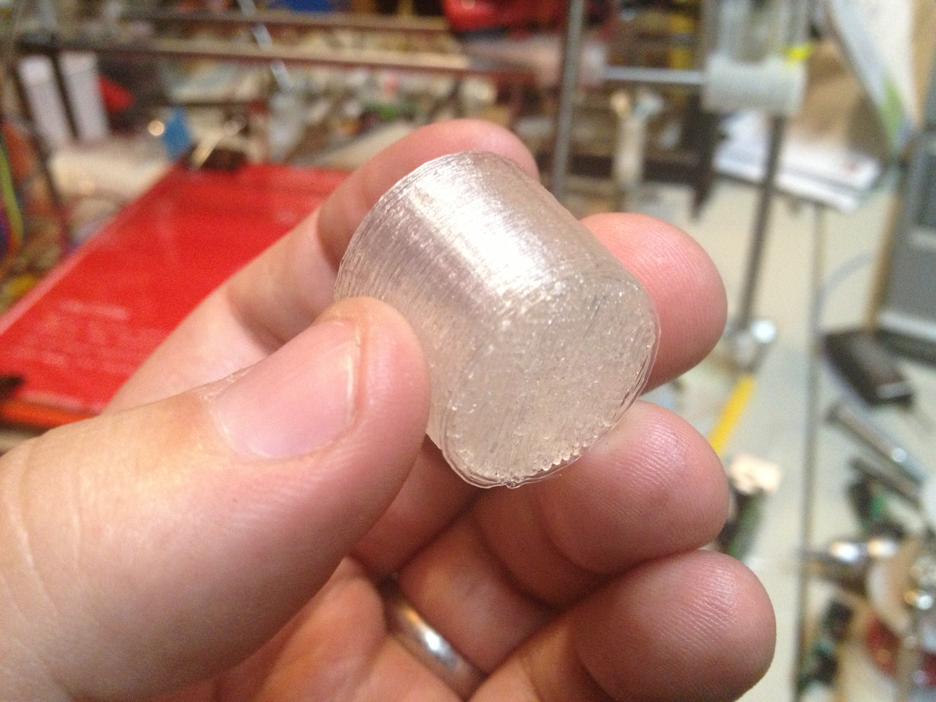
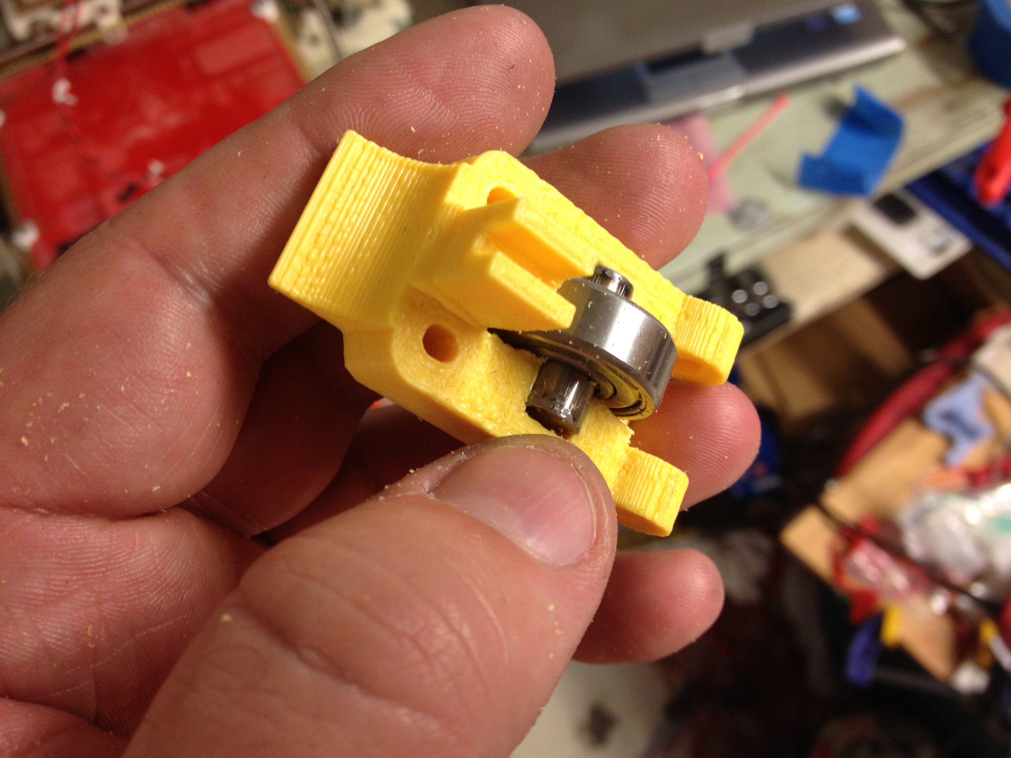
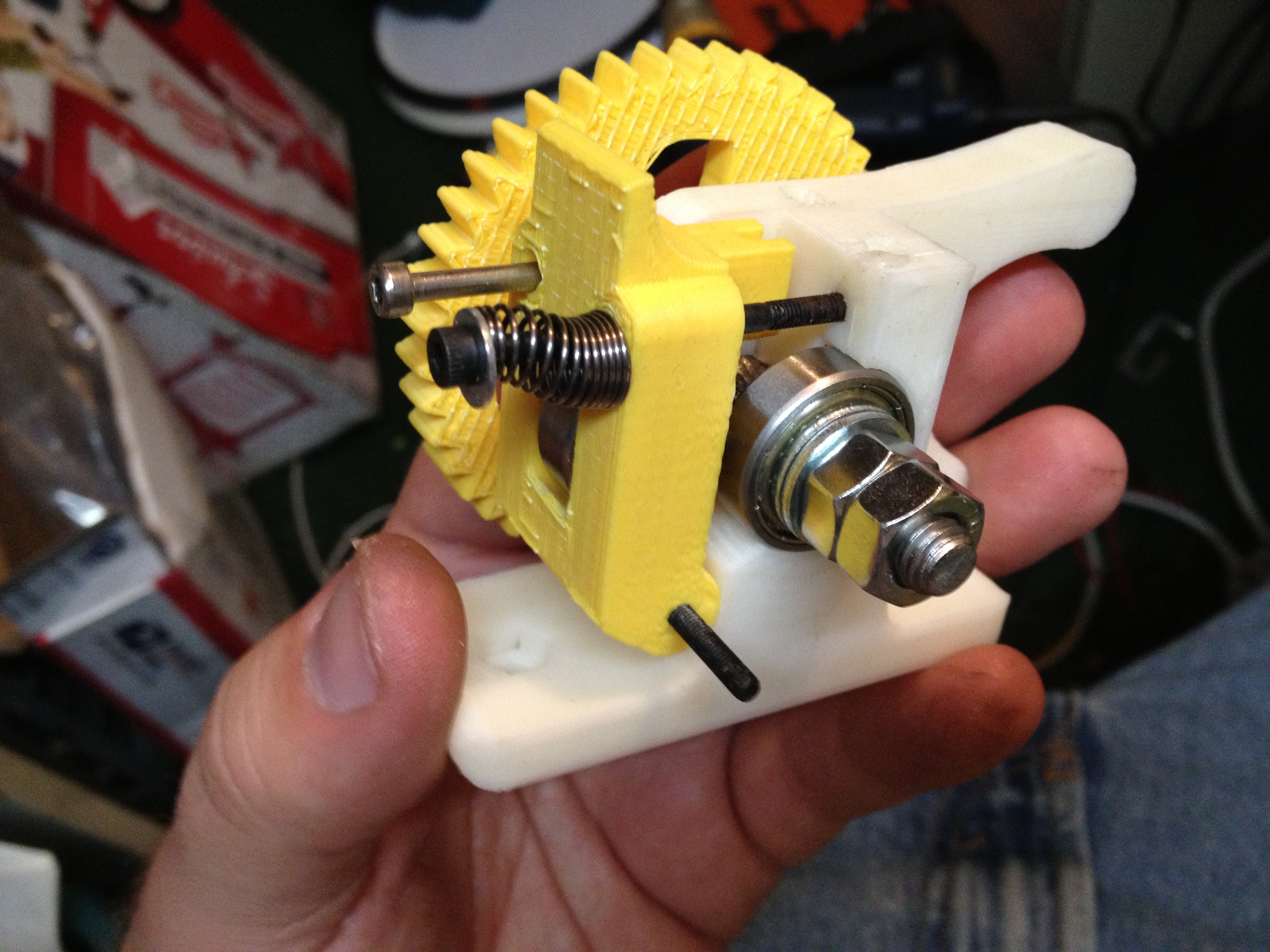
I also printed out an idler:
…two extruder parts with bottoms designed for the Budaschnozzle, two spare Open-X carriages for me:
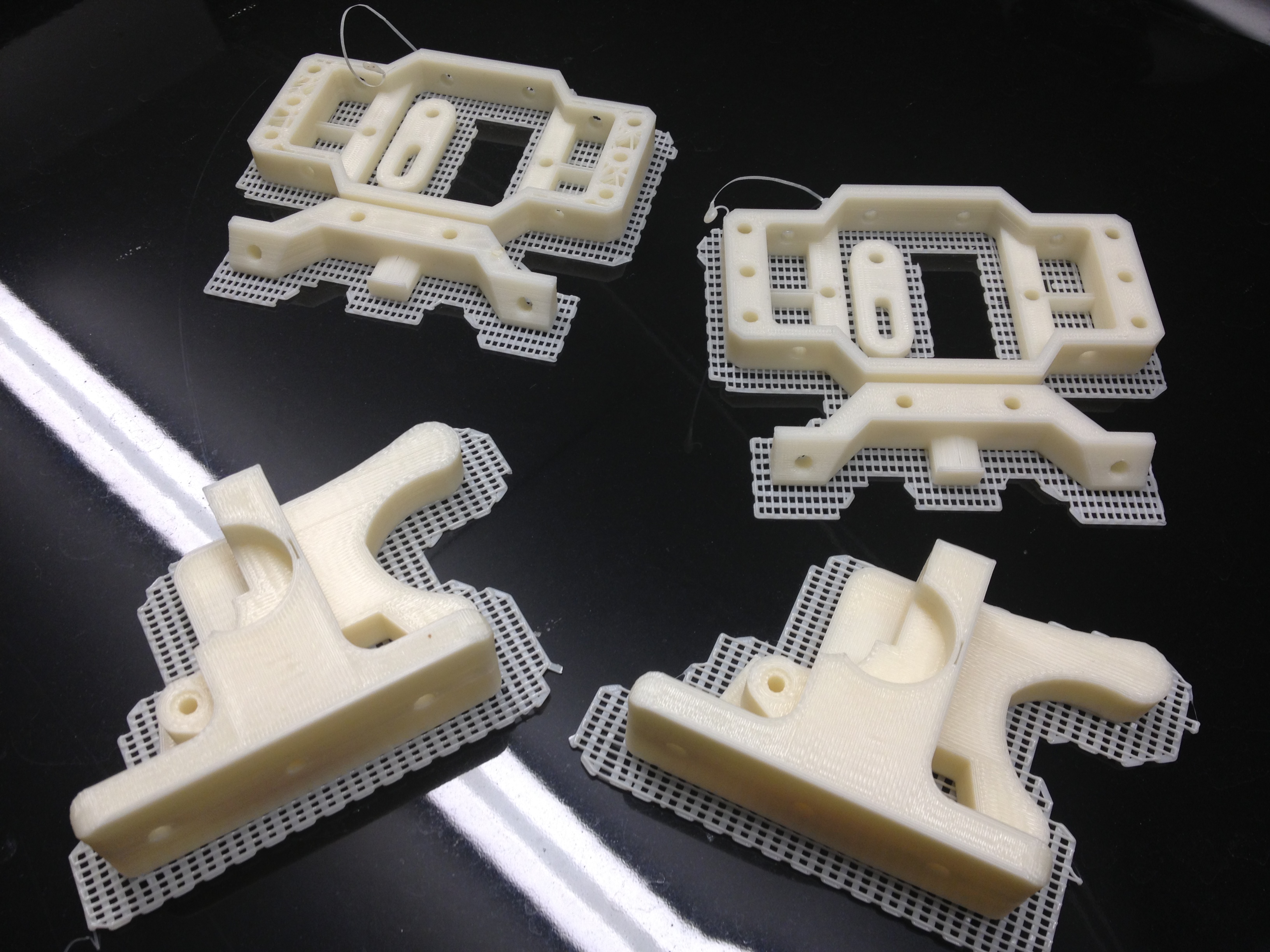
…and the both gears for the extruder:
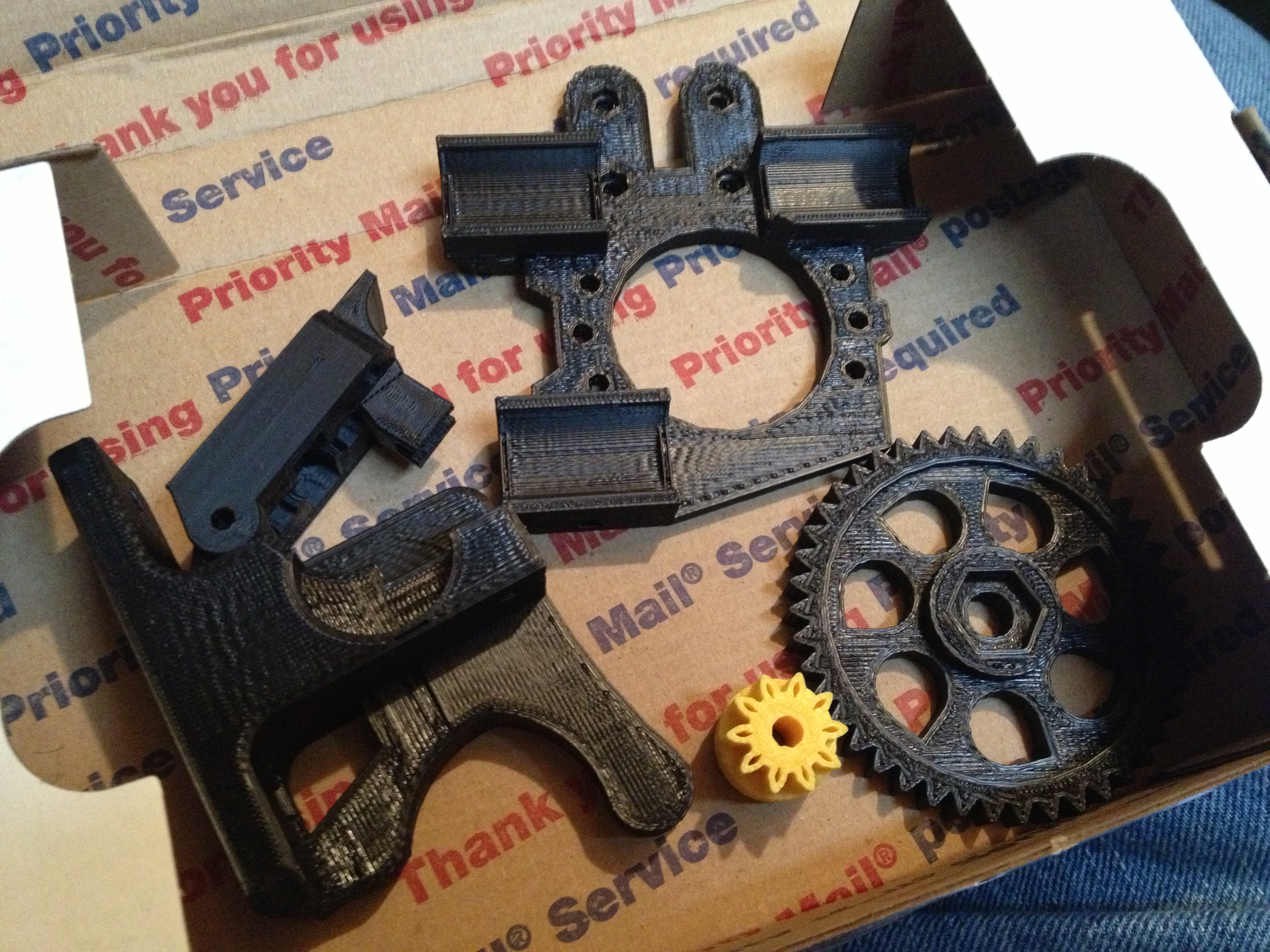
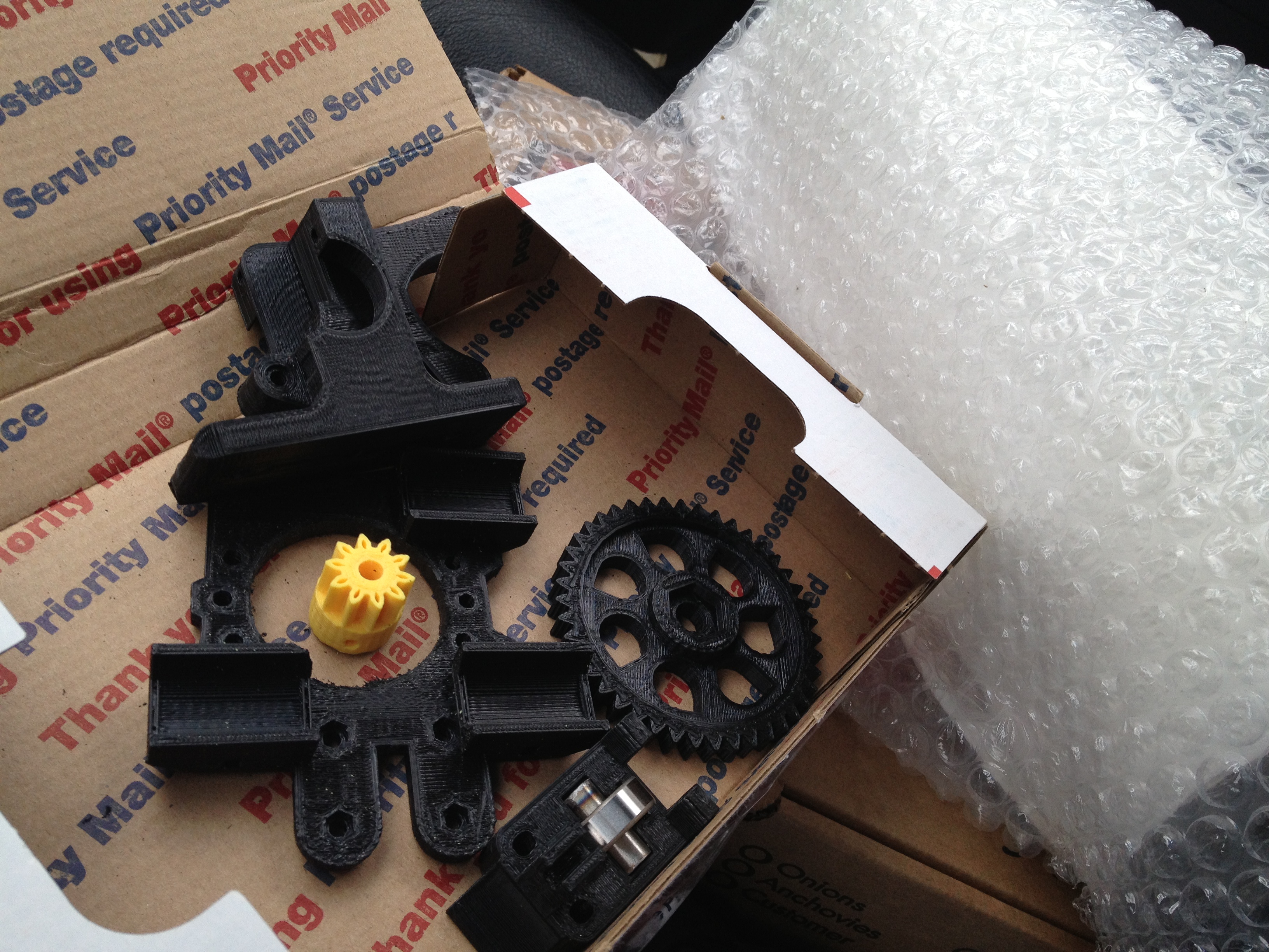
Since I was printing ABS extruder and carriage parts, I decided to print some for my brother as well (whose RepRap parts were printed by my printer), since I now knew the PLA carriage I’d given him would melt. 🙂
Here is what I mailed him:
Around this time my brother had mailed me a picture of the frame he’d built from the parts I’d given him:
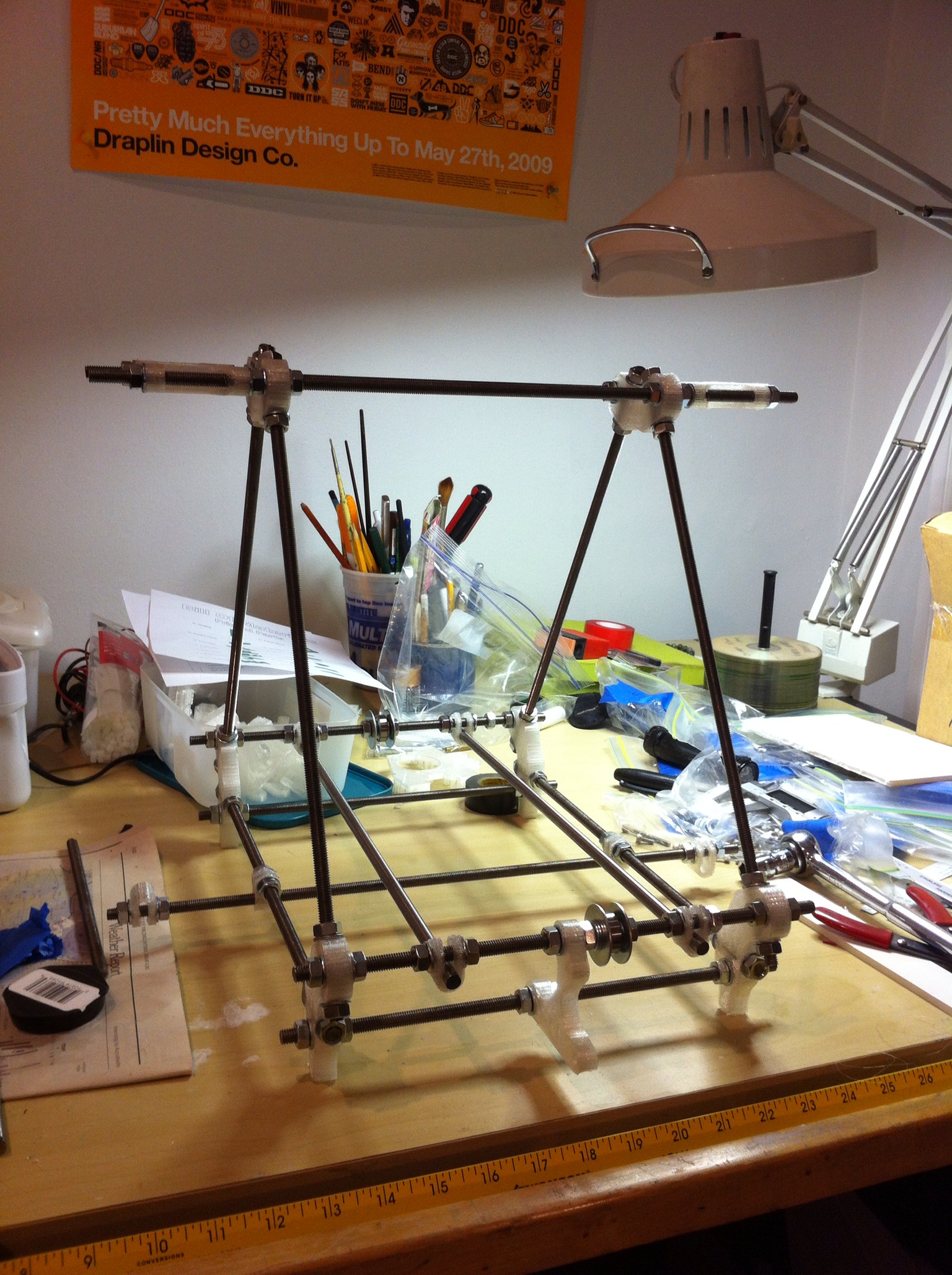
Jon, if you’re reading this, here’s more motivation for you to finish up and get your printer printing! 😀
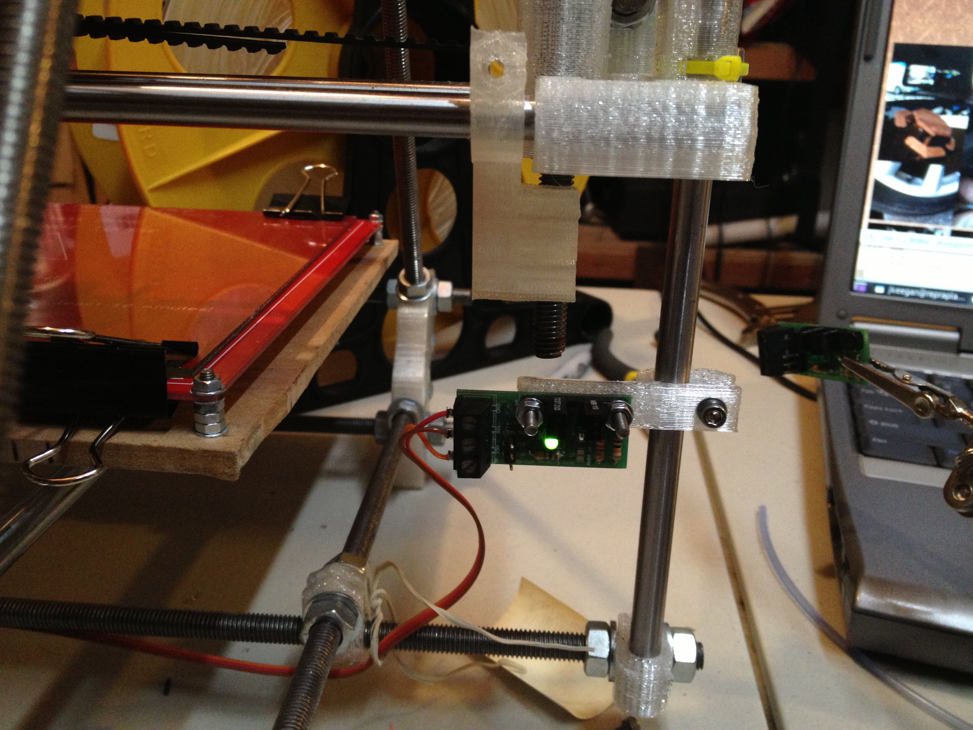
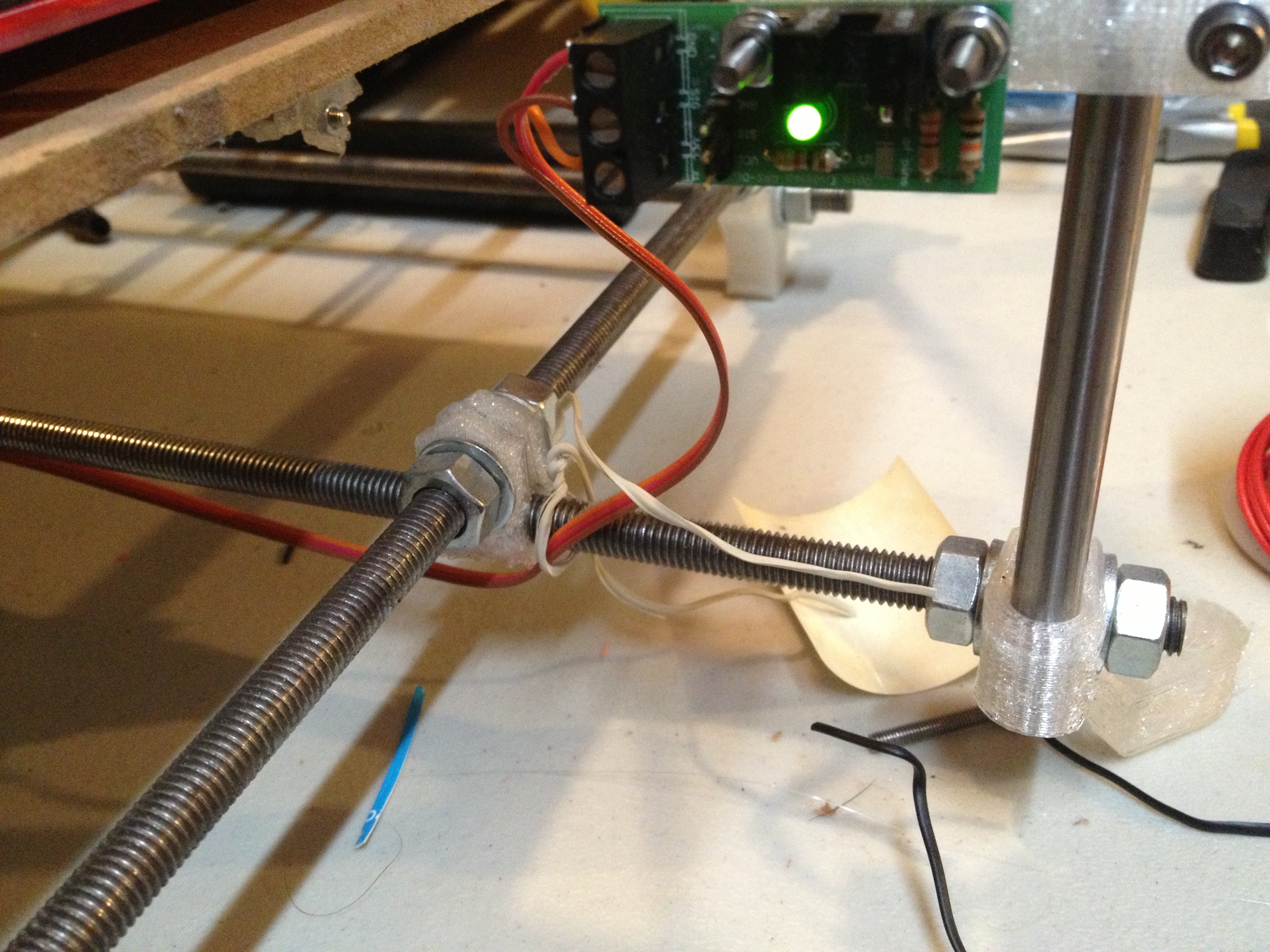
Ok back to the Z opto endstop.. At first I mounted the opto endstop board on a standard holder printed out of PLA, which you can see in the upper right-hand corner of this picture:
I really wanted that to be adjustable though. I found this “Really High accuracy adjustable Z Endstop for Prusa” piece, printed it, and attached the opto-endstop board to it, and mounted it on the RepRap:
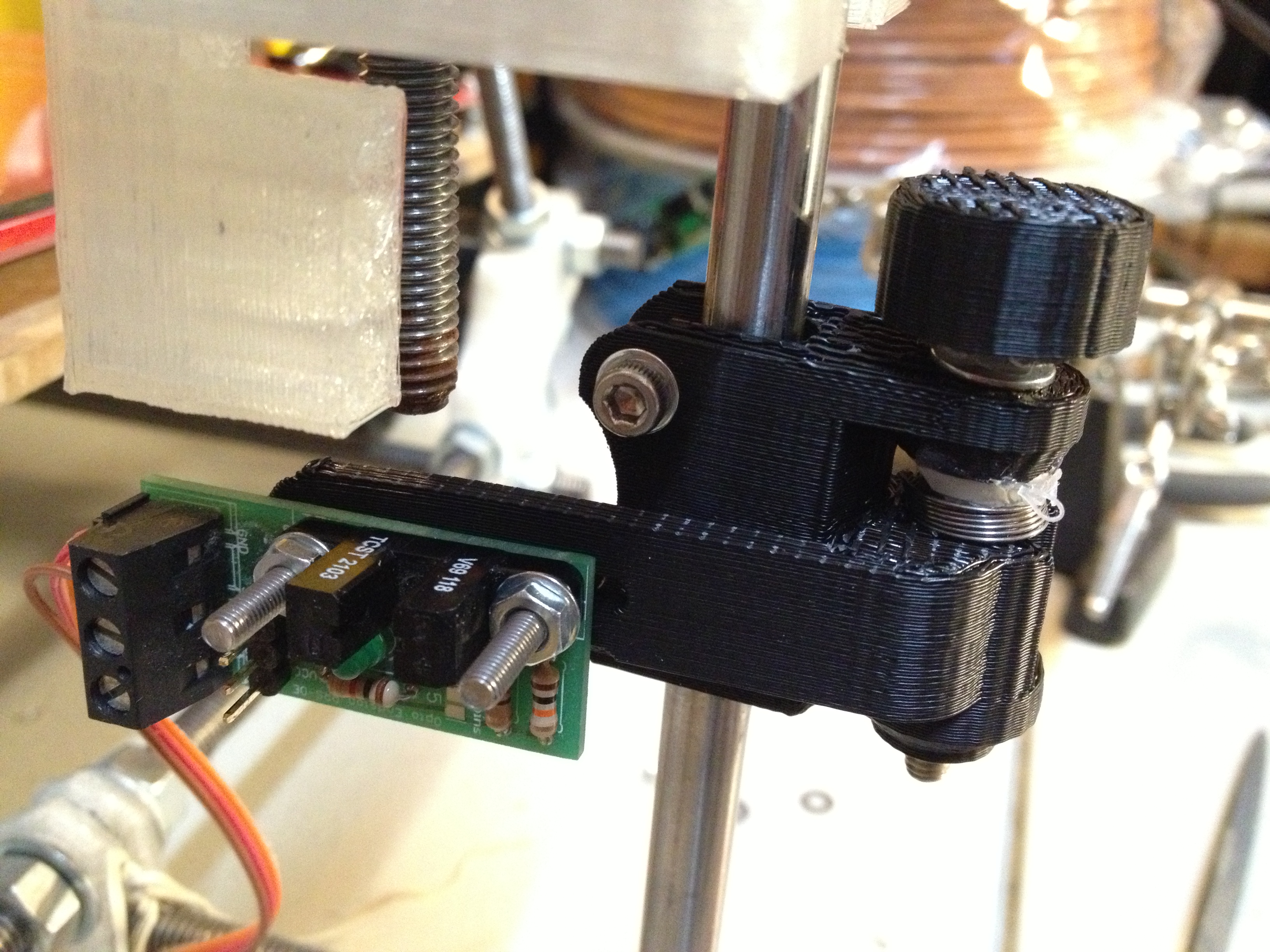
(Actually I mirrored the arm part, since I wanted to mount this on the right side of the machine instead of the left. The mirrored arm piece is now on thingiverse here).
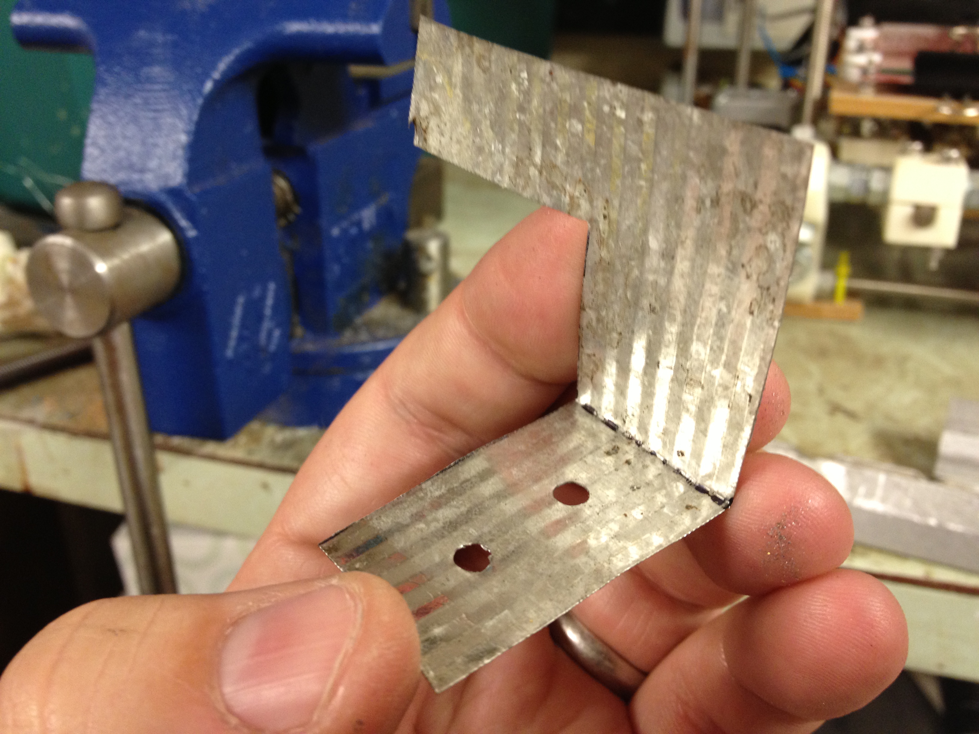
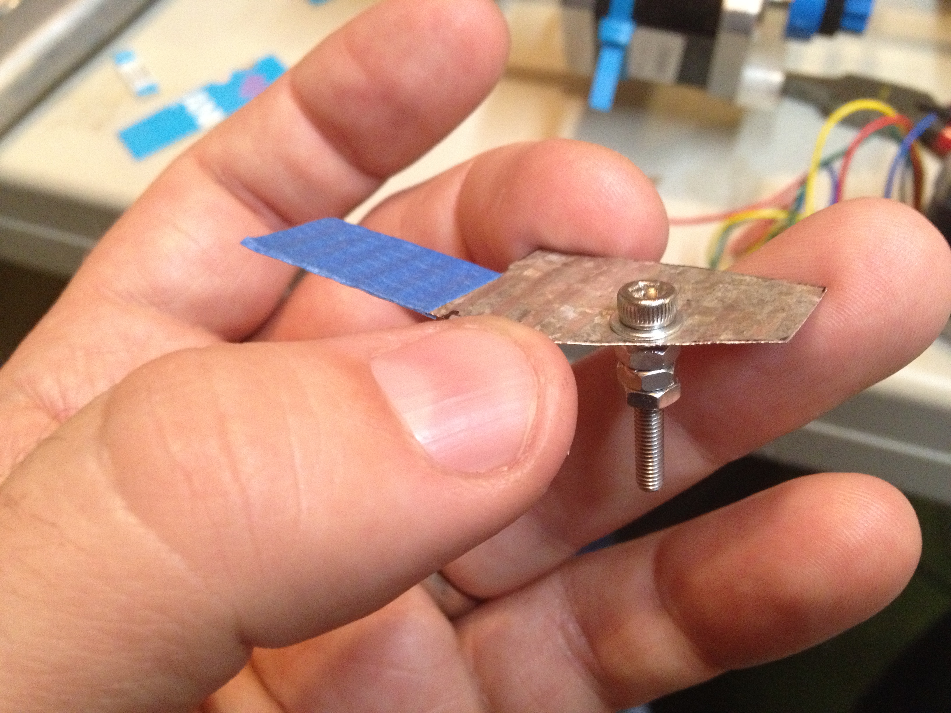
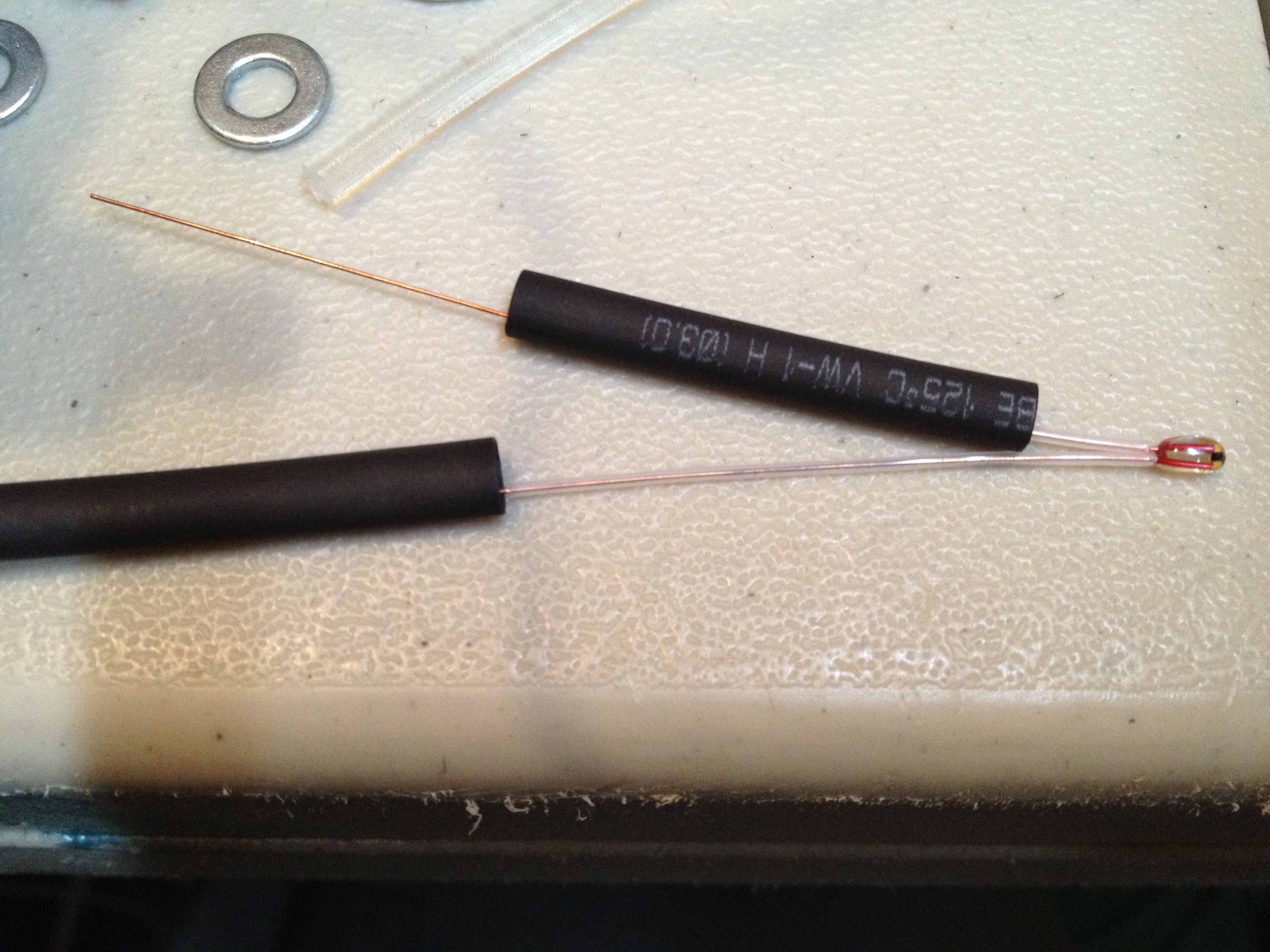
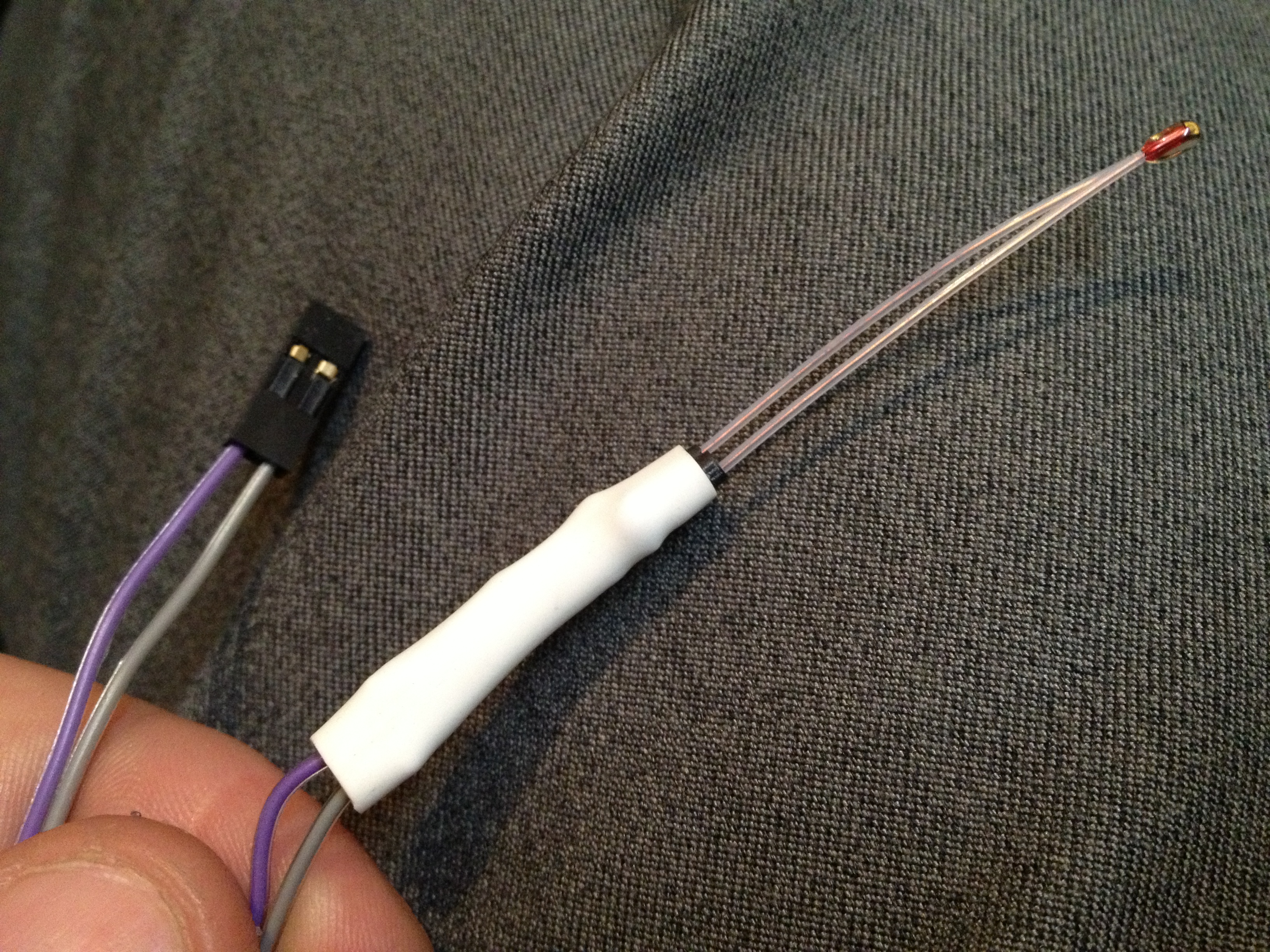
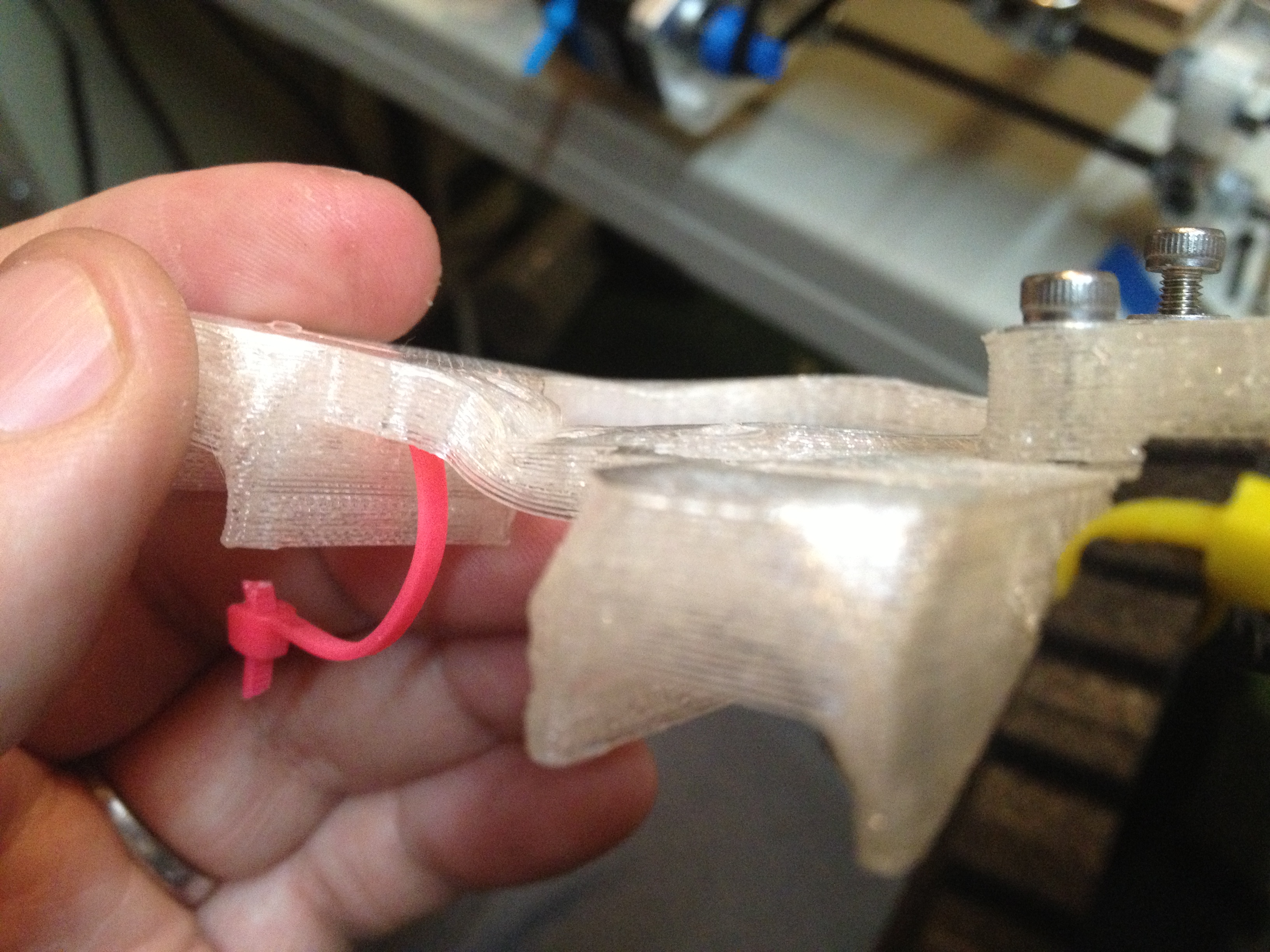
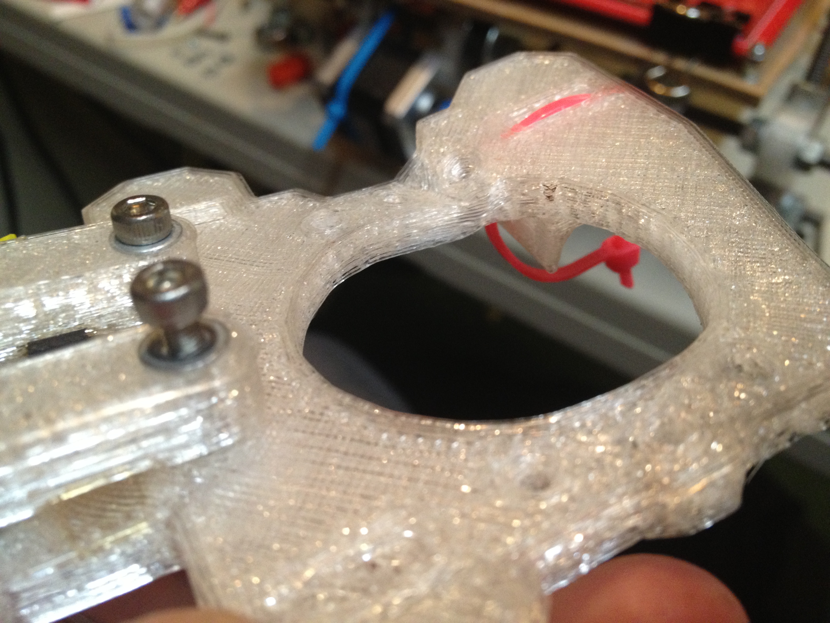
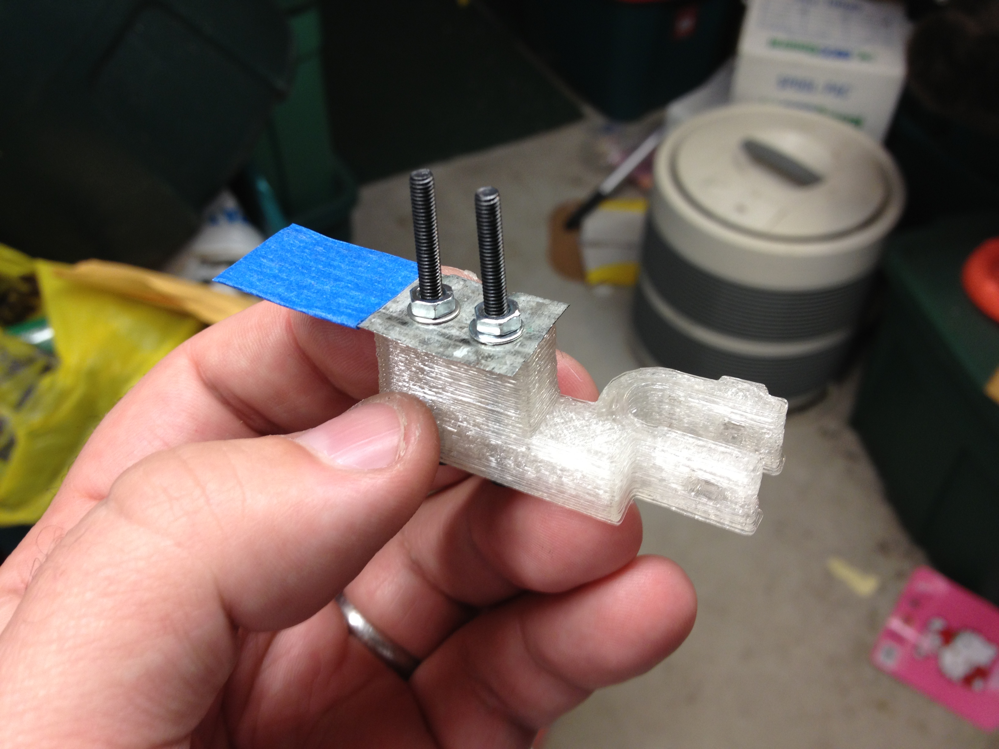
Back to my Z-opto-flag holder, here it is with the tin cut and with tape on it:
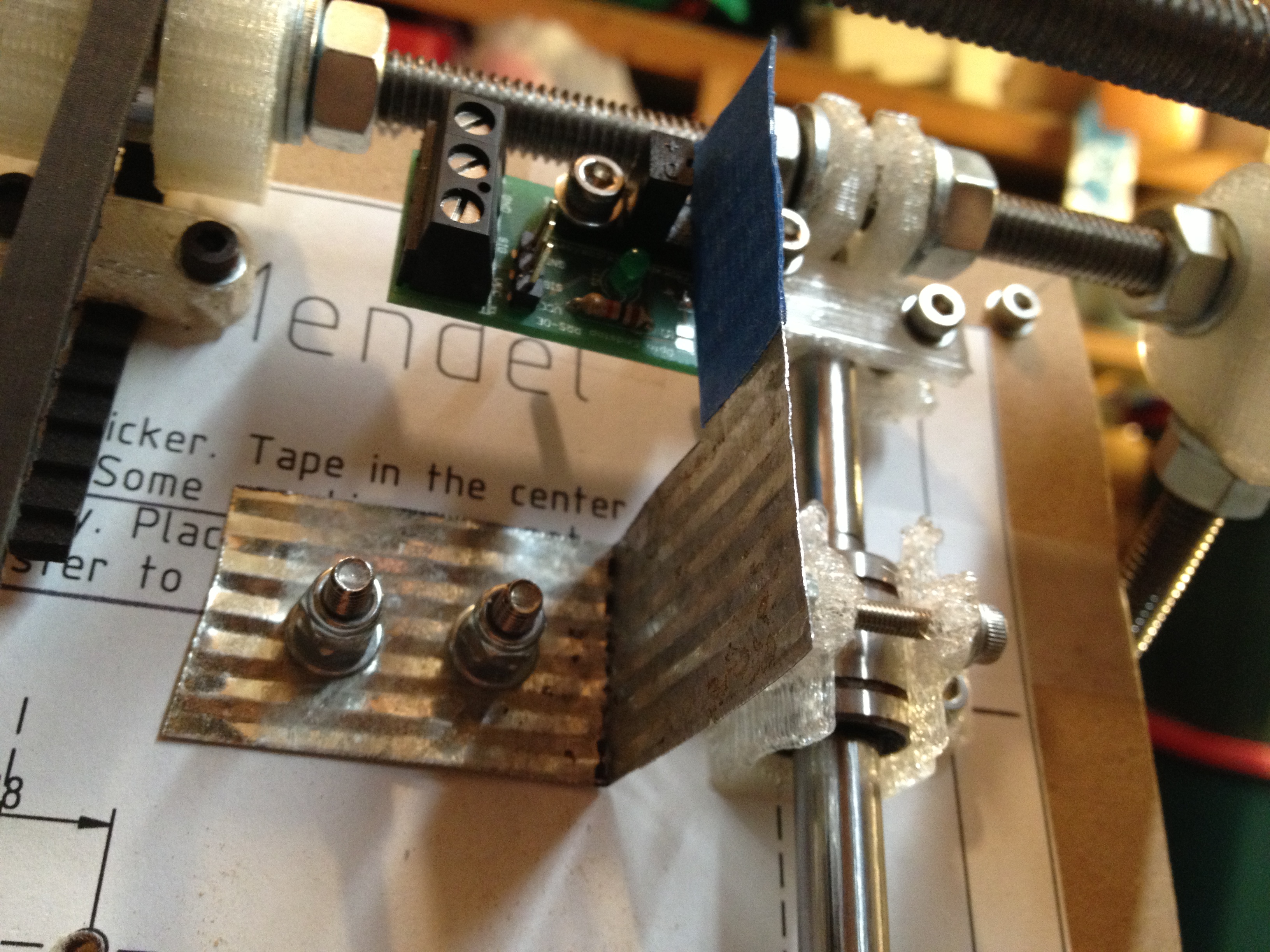
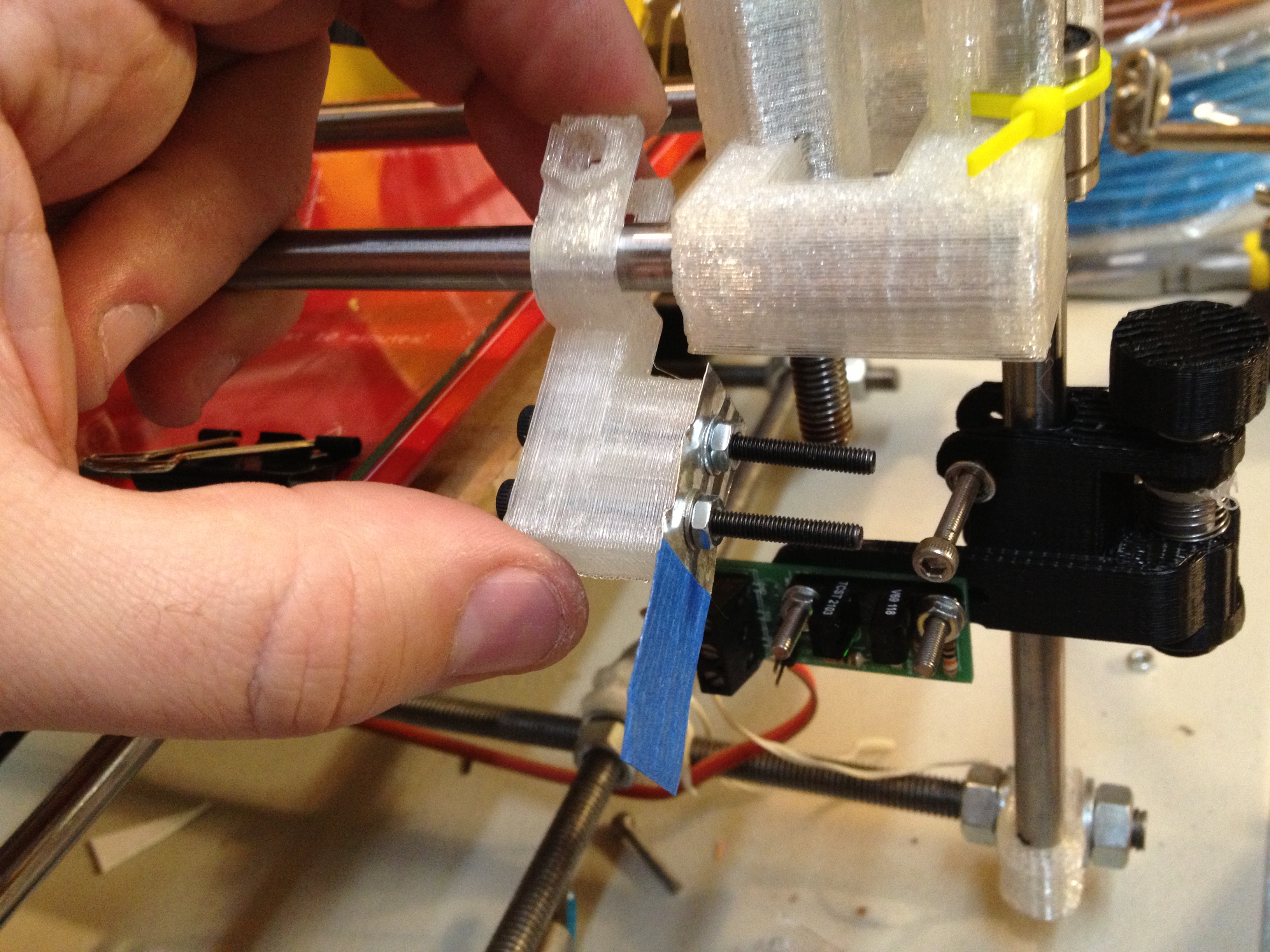
…and here it is installed and ready to swing down in place:
…and here is the first homing of the Z axis with these parts:
I just uploaded it to thingiverse finally, while writing this post. 🙂
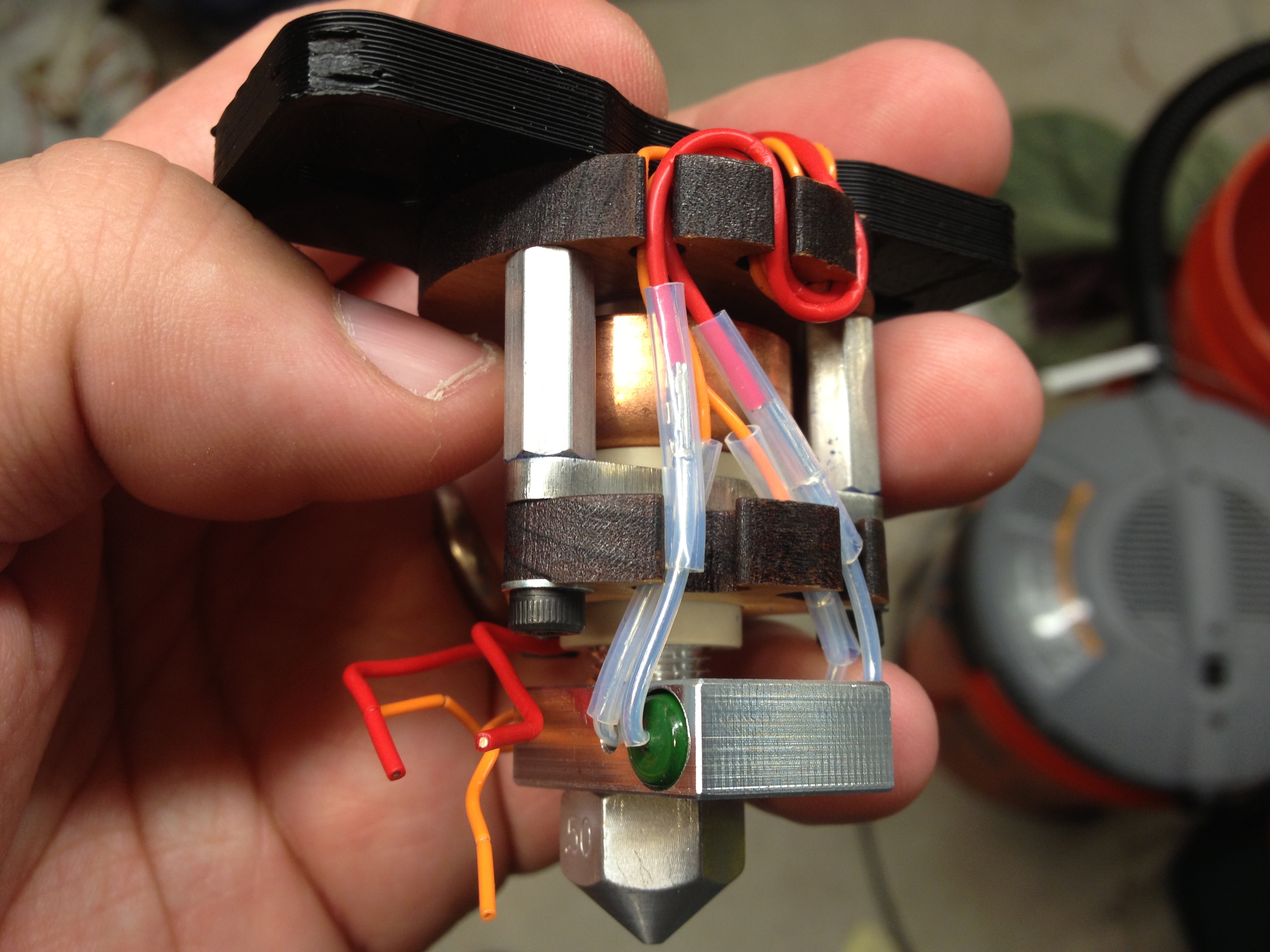
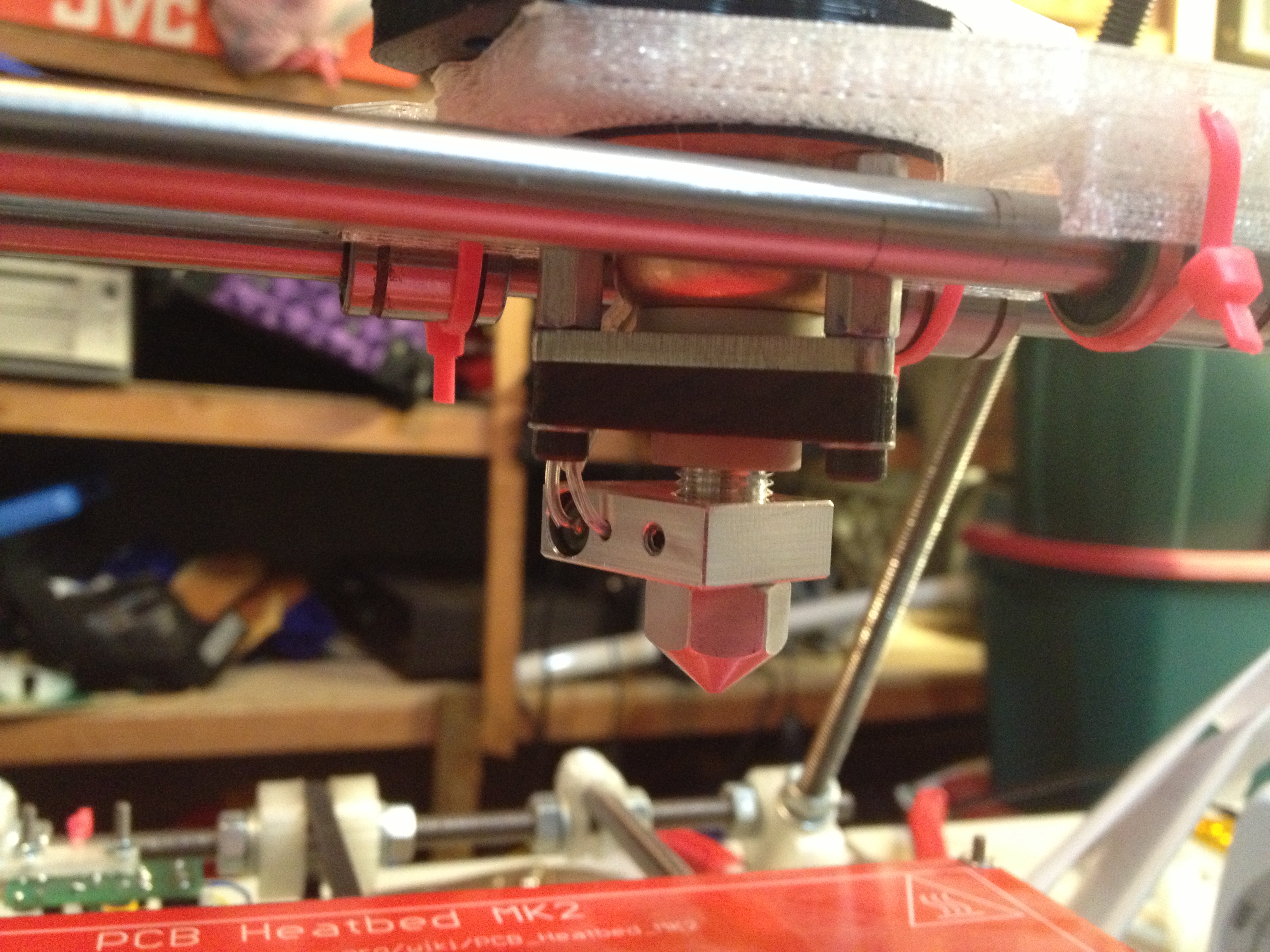
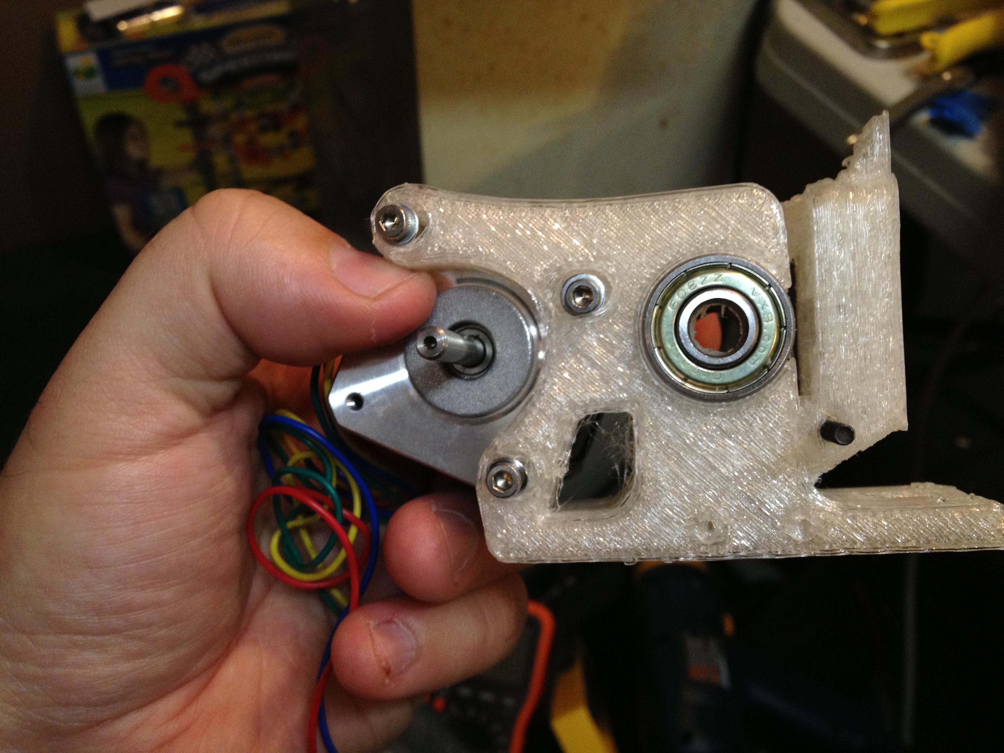
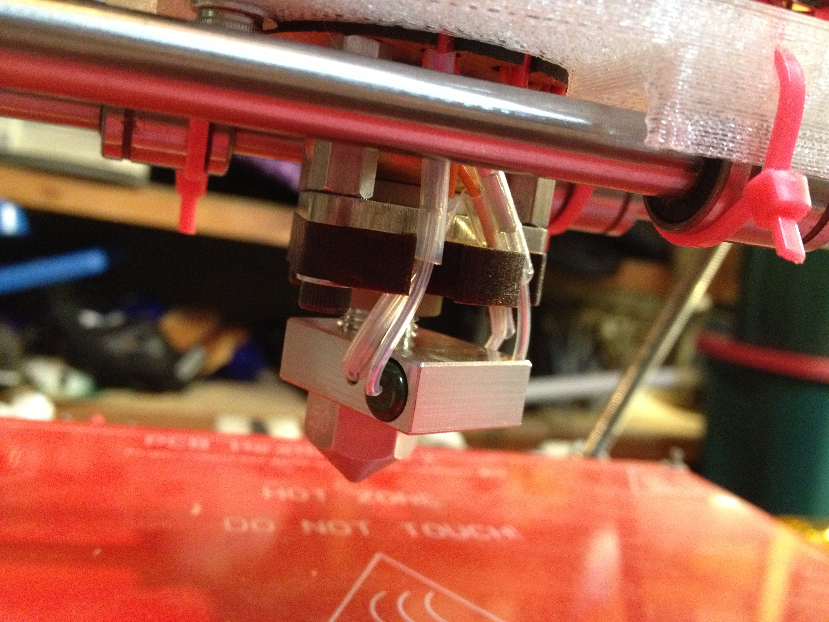
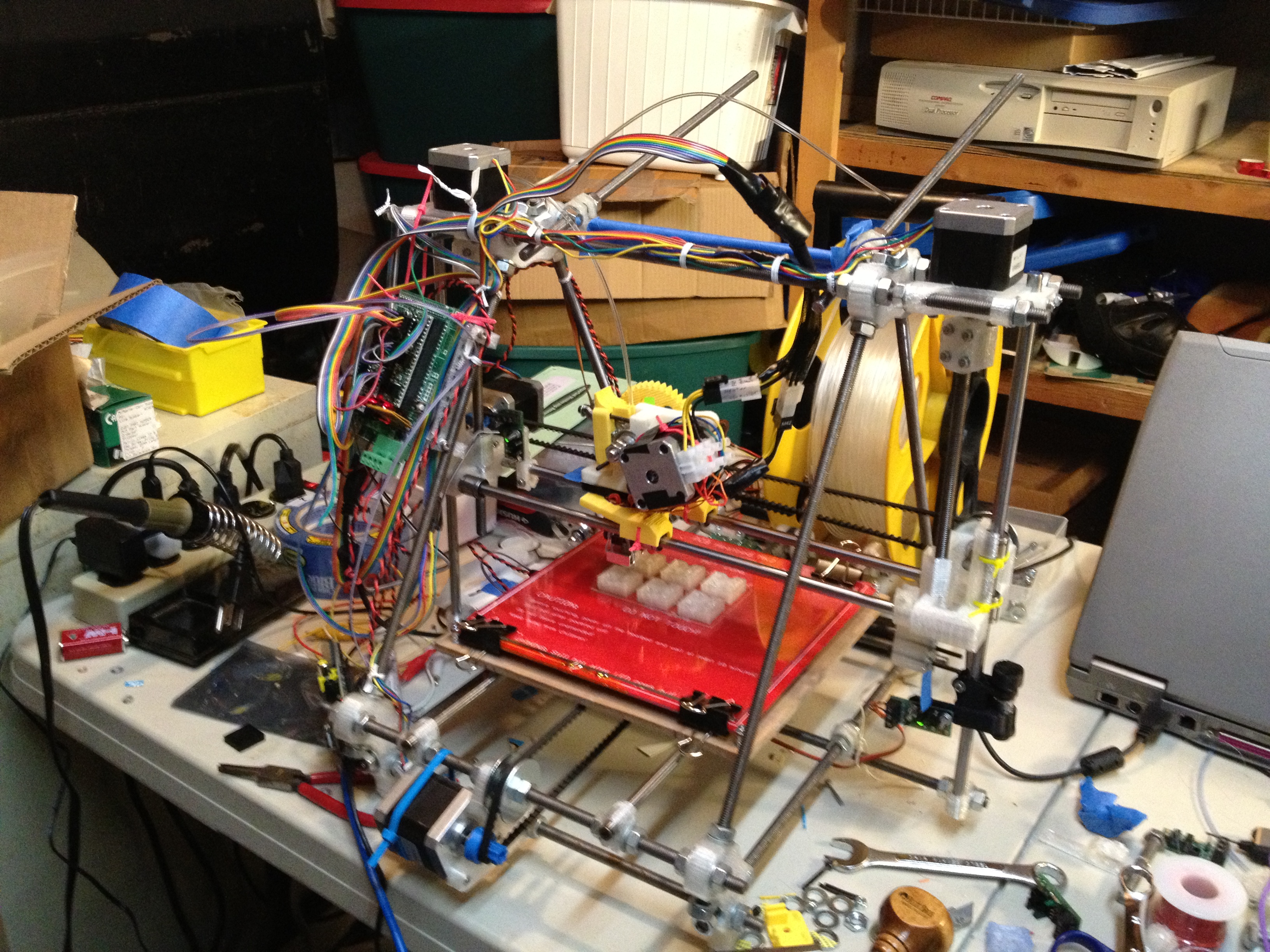
So then I mounted the Budaschnozzle in the new ABS X-carriage. It got stuck at first, and after I managed to remove it I filed the edges of the inside of the circle a bit so it was more easily removable.
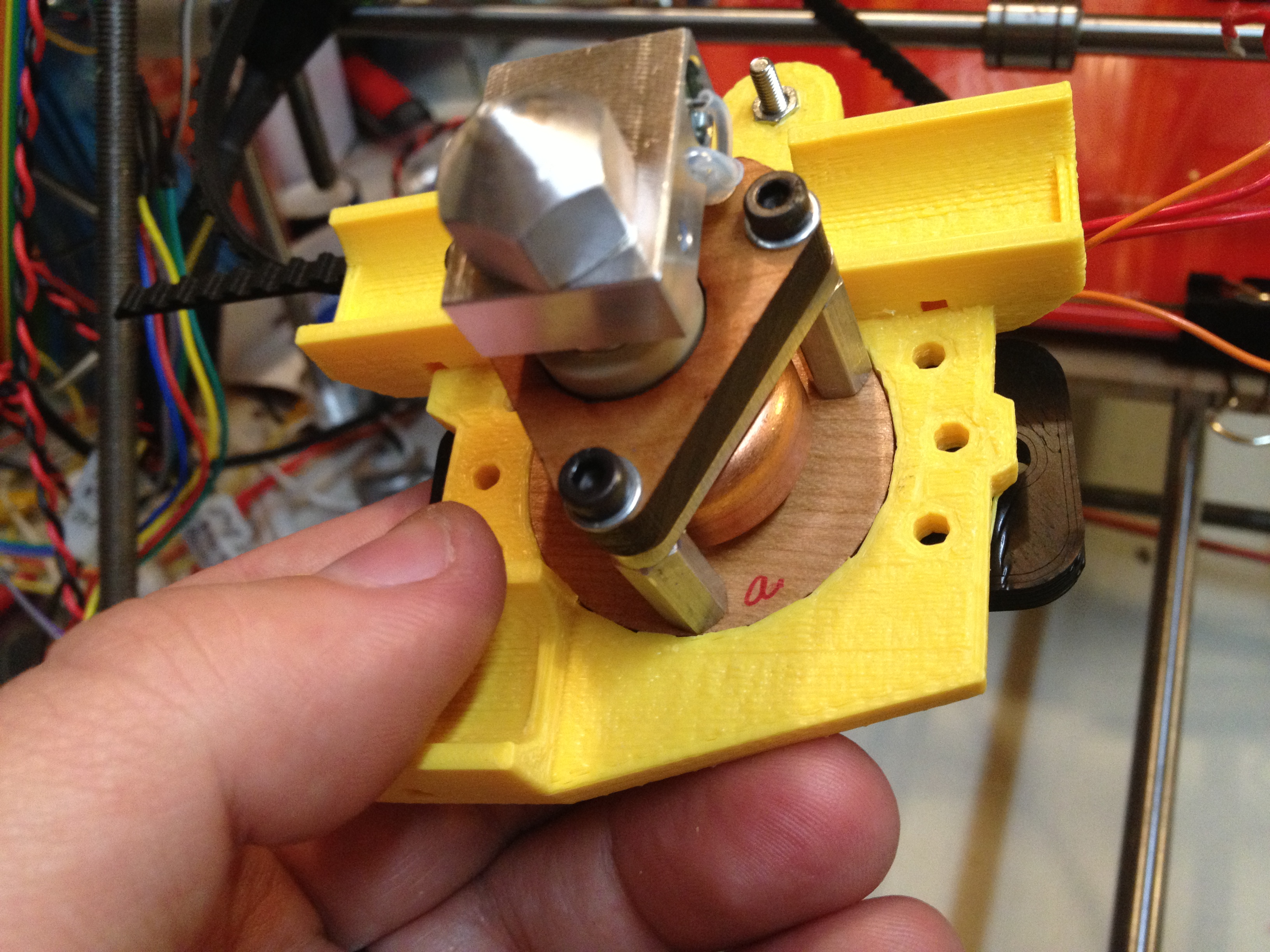
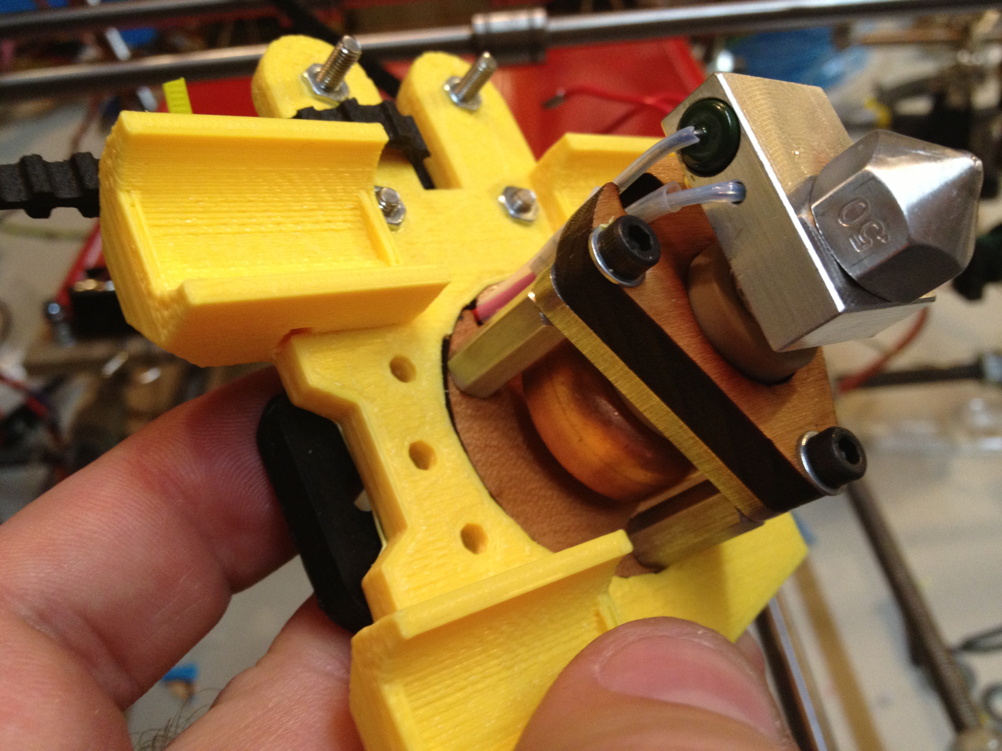
Then I assembled the new ABS extruder:
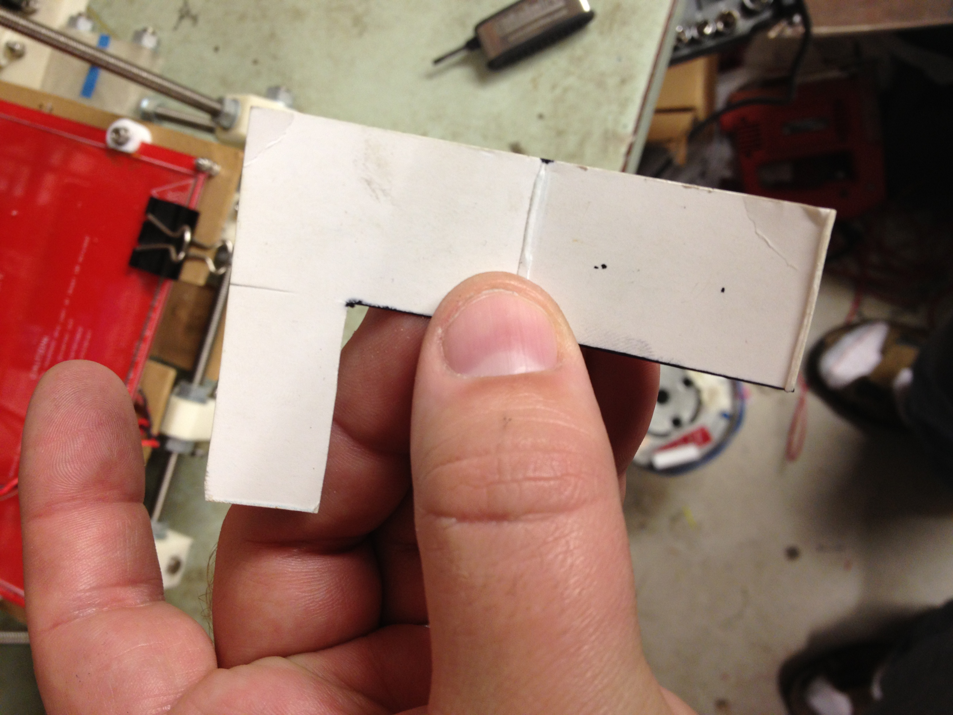
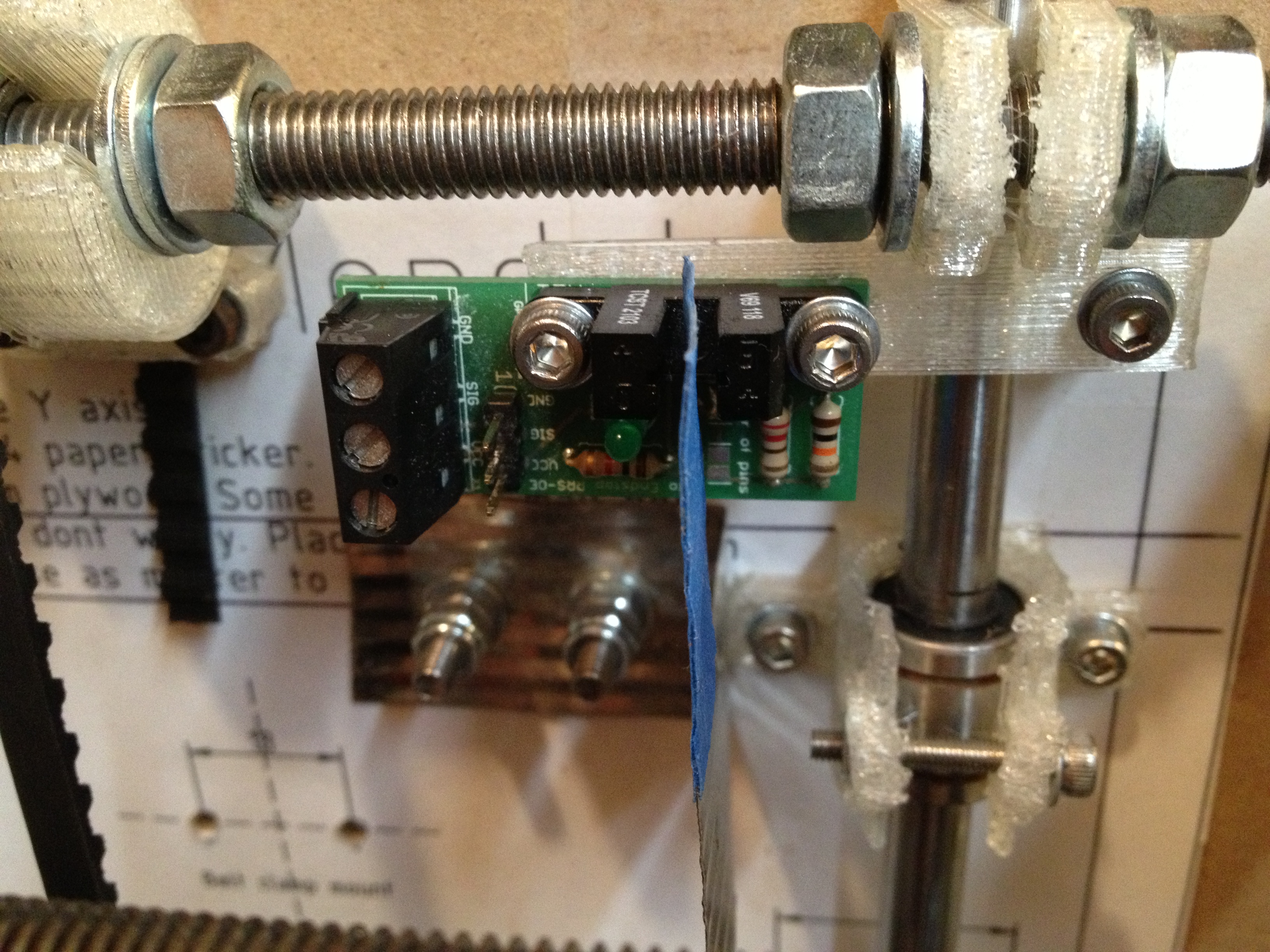
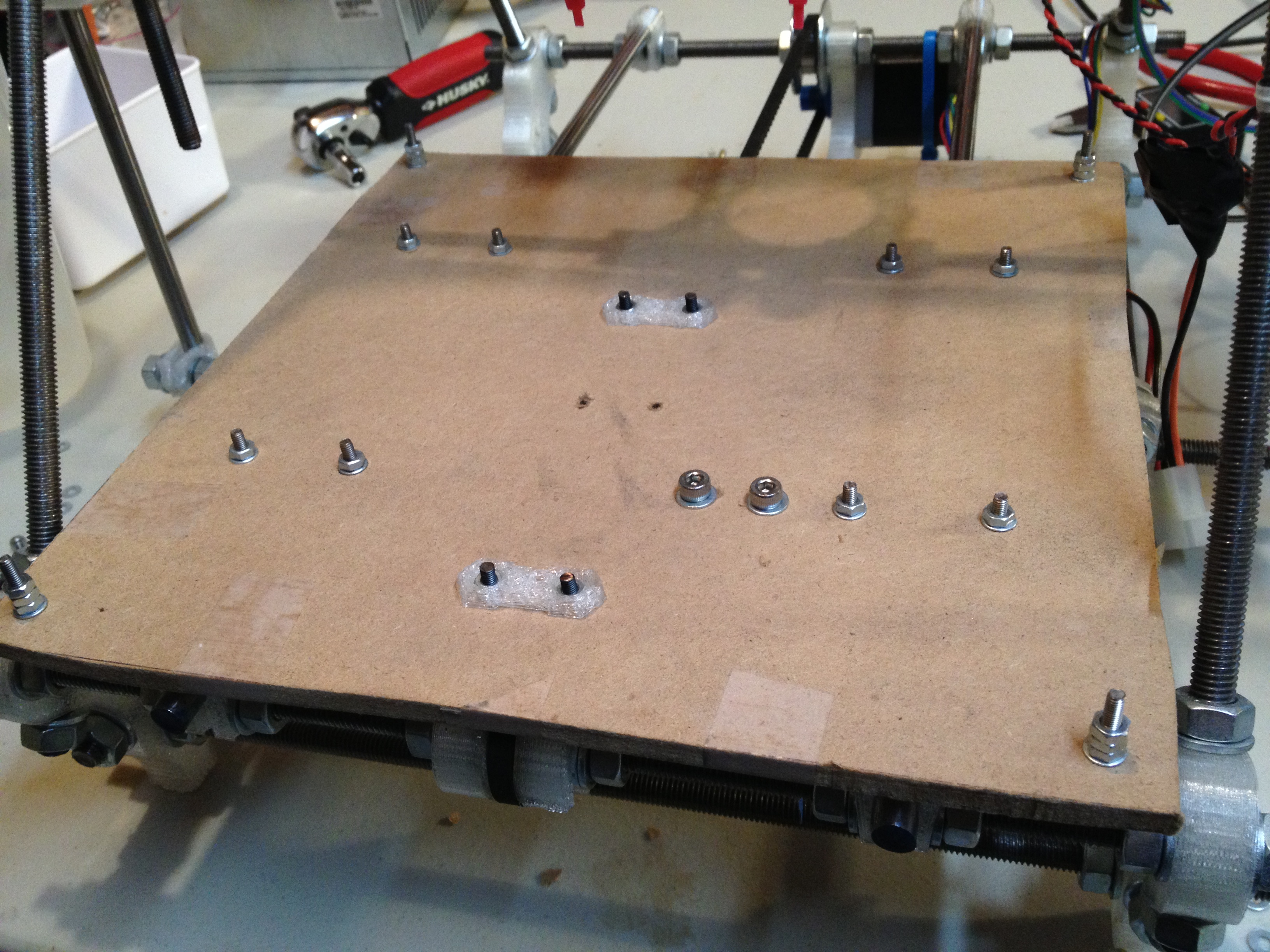
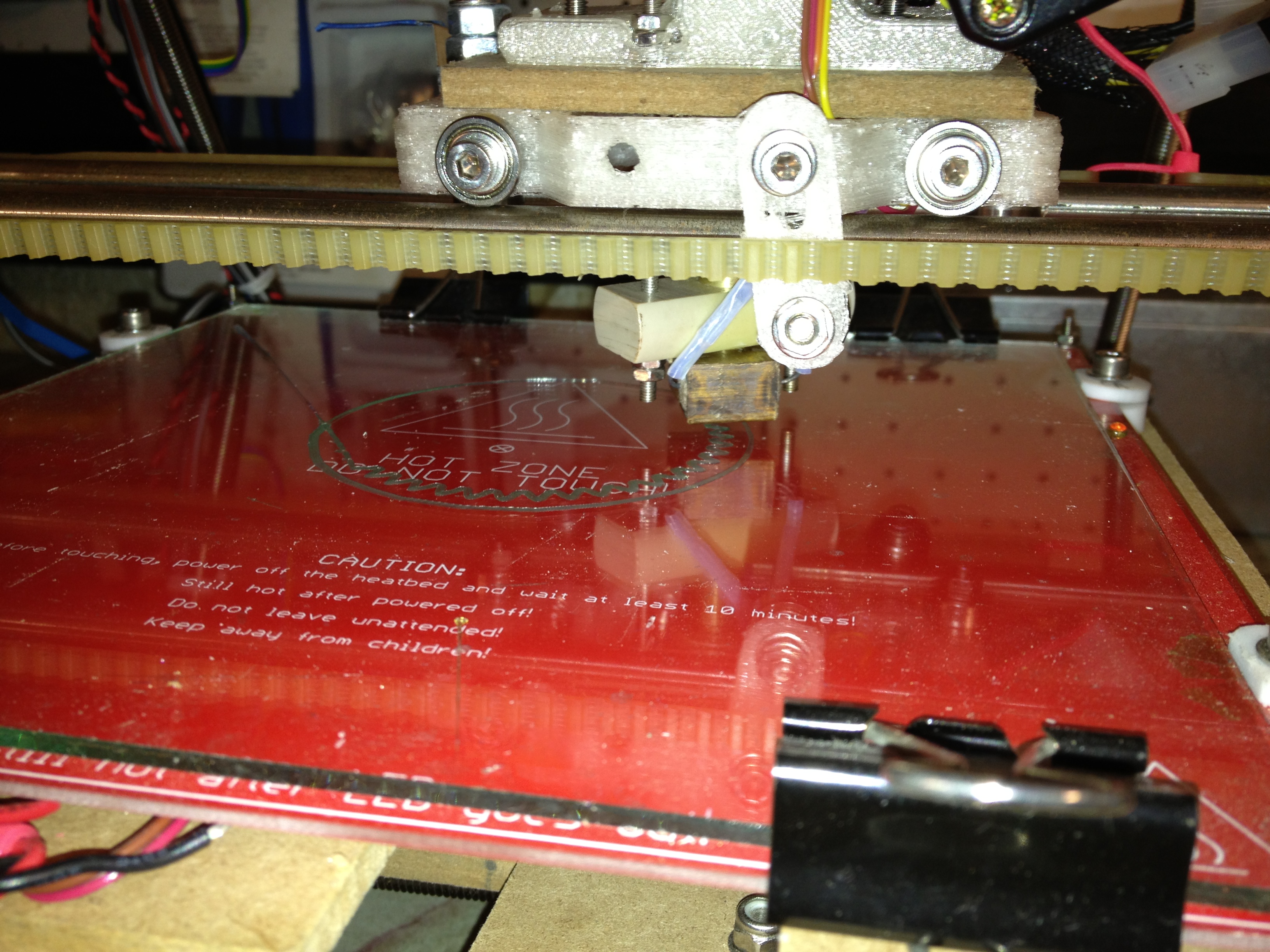
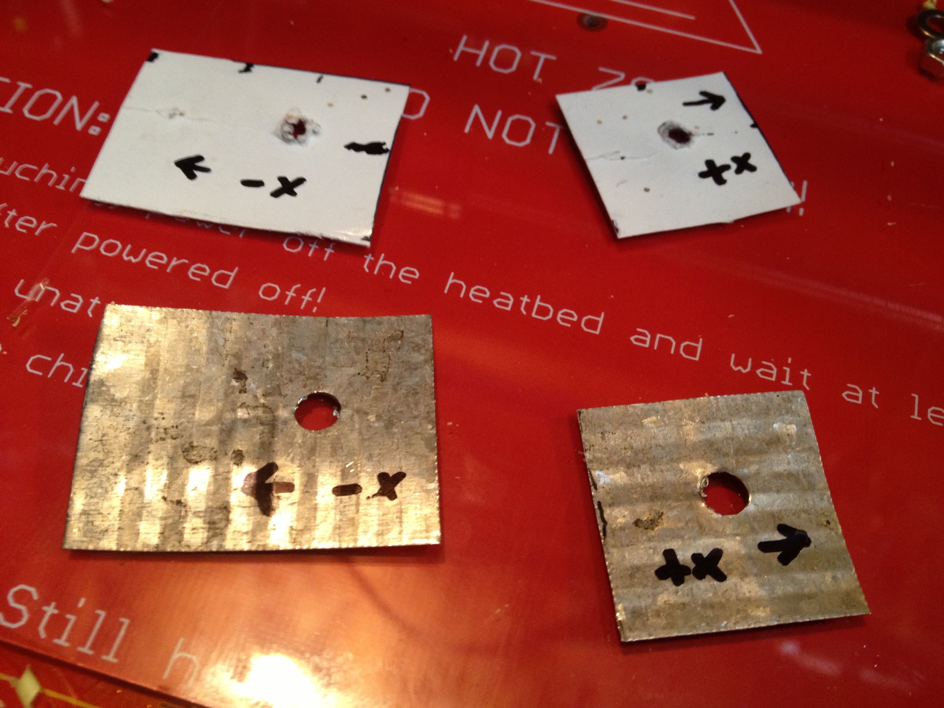
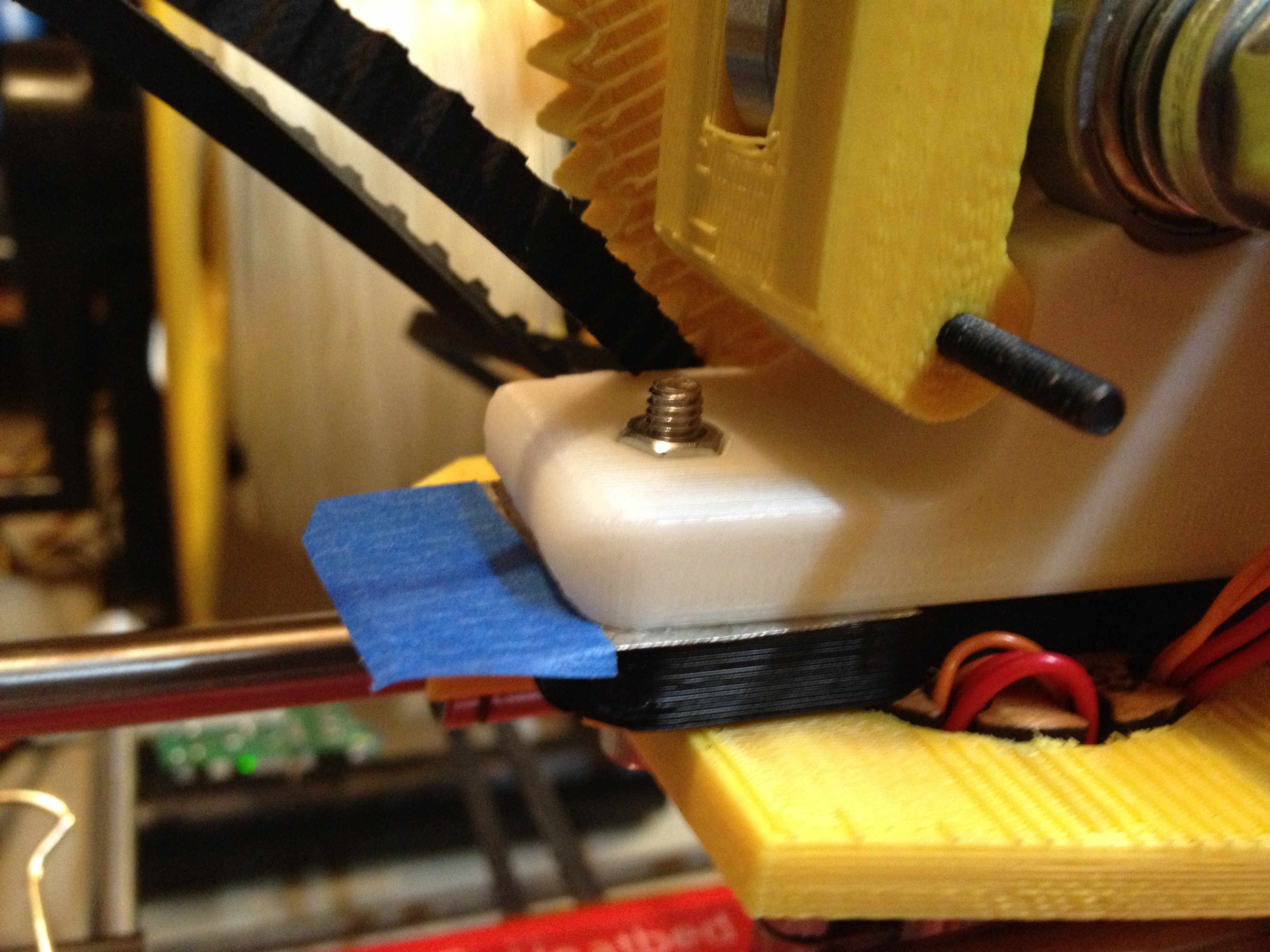
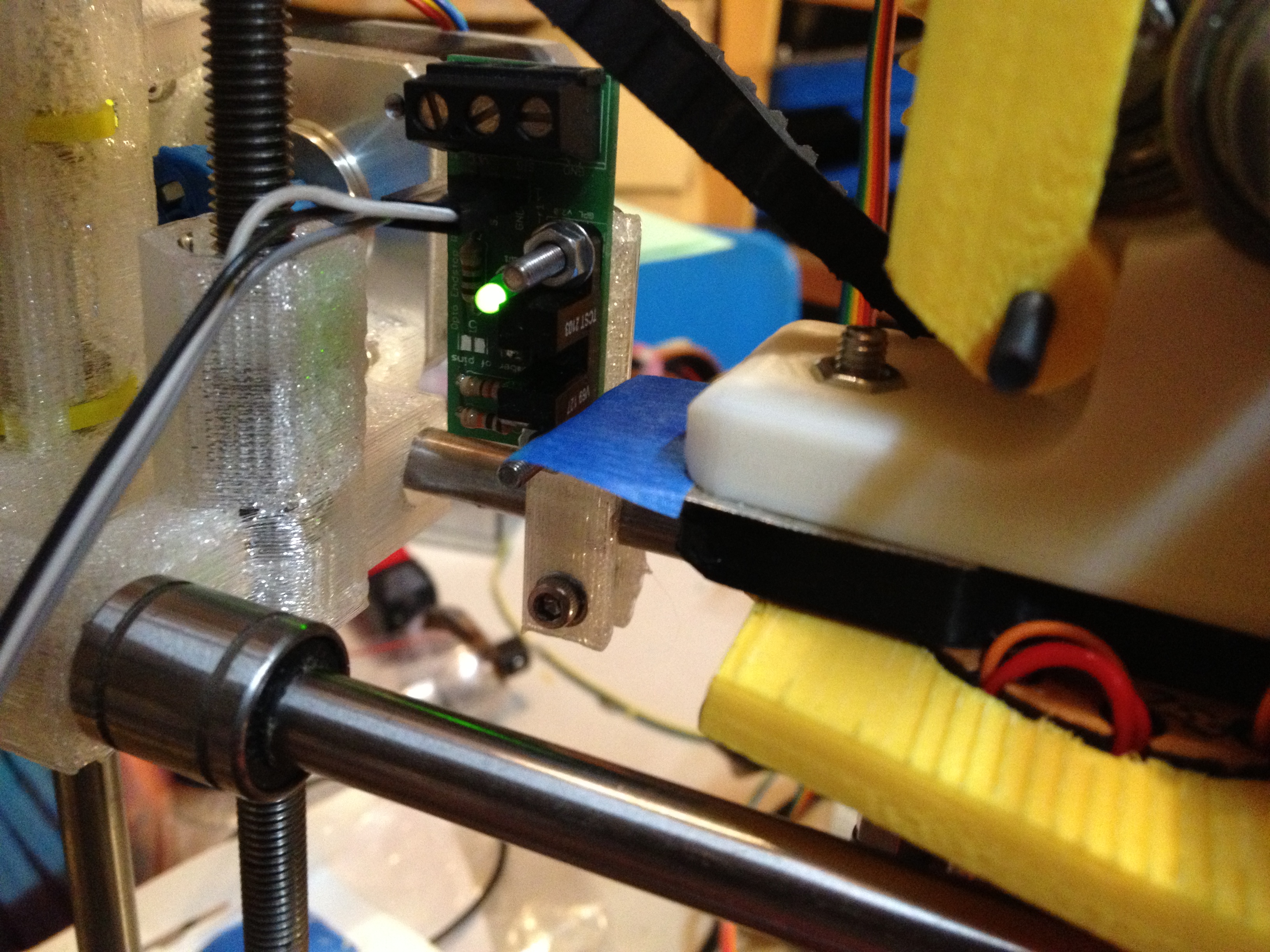
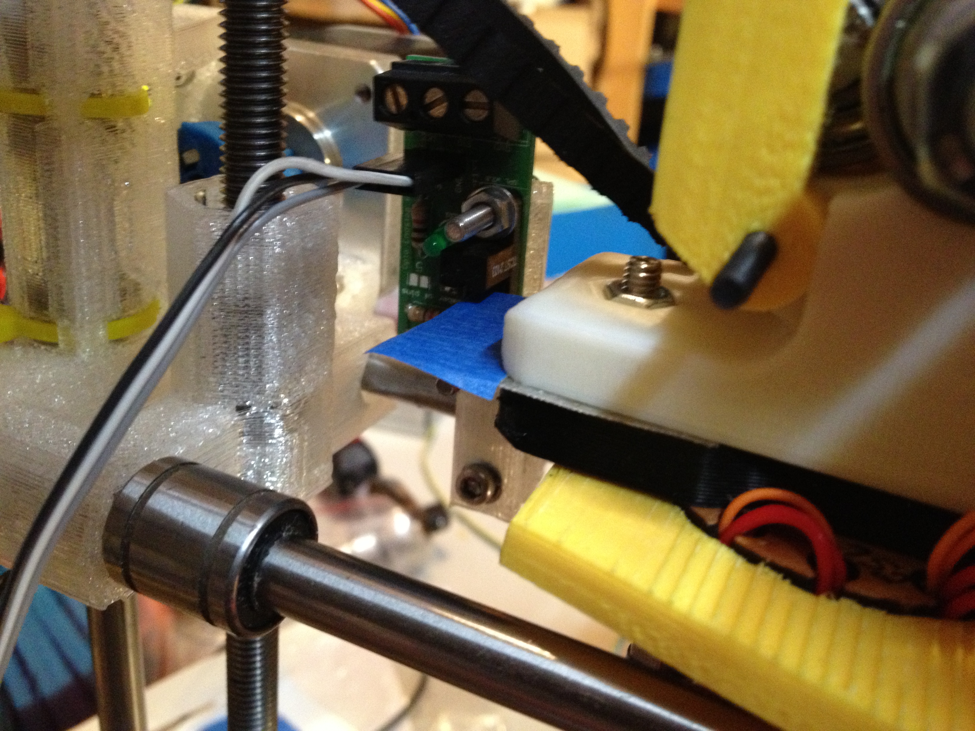
Then I realized what I was going to do for an X endflag.. I don’t know if it was by design or chance, but when you’re using a Budaschnozzle mount on the Prusa IT2 x-carriage I was using, a piece of tin right between the plastic part of the Budaschnozzle mount and the extruder is at exactly the right height for an opto endstop board mounted on a standard Prusa IT2 endstop holder.
I modeled them with paper then cut them out of tin after (I say “them” because not only did I put the X endflag beneath the left of the extruder, but I put another shim of metal beneath the right of the extruder so it was evenly balanced).
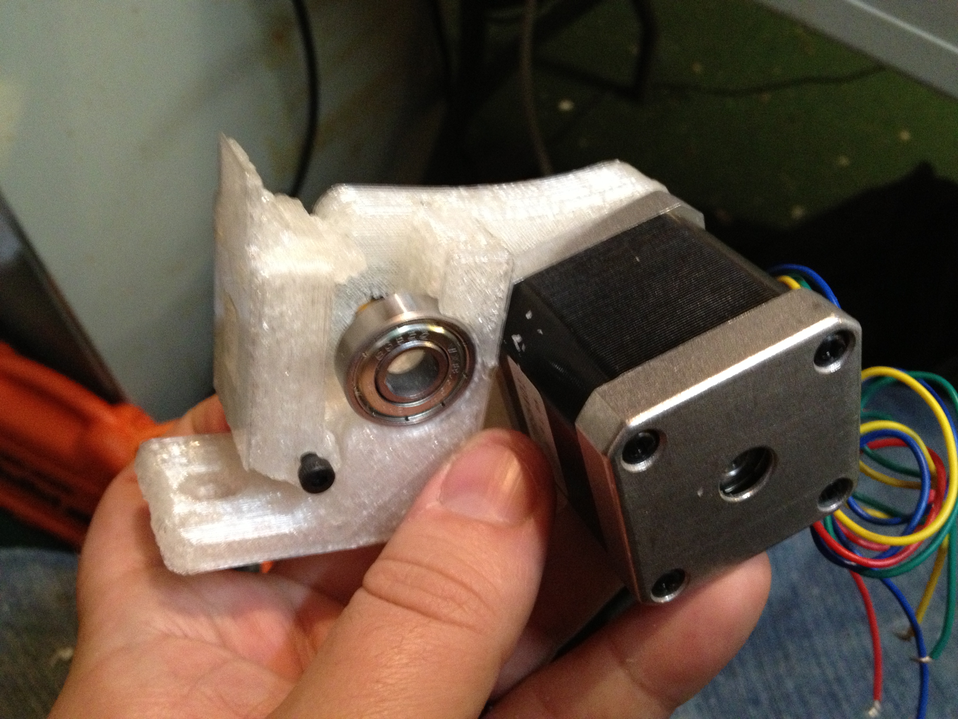
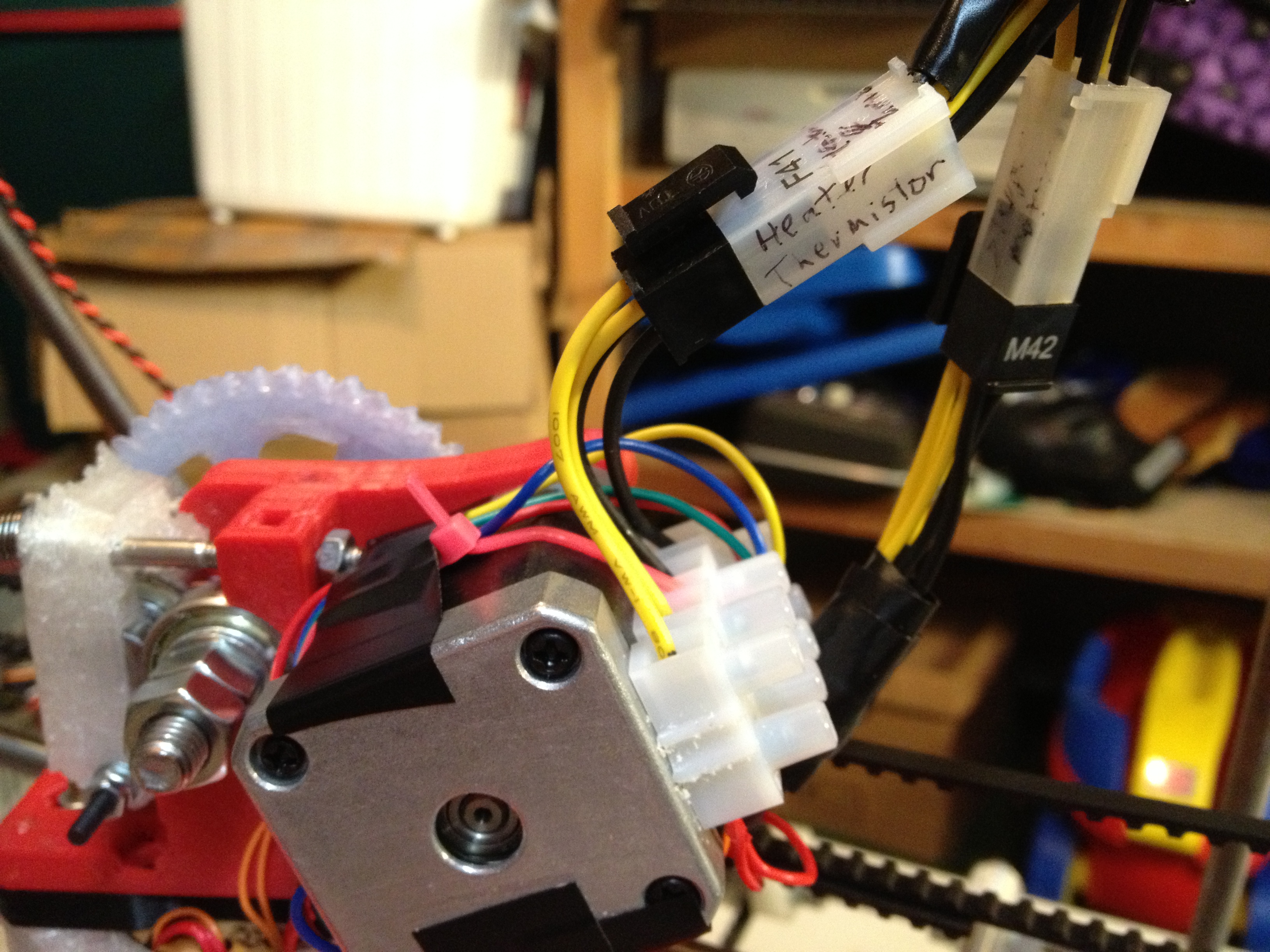
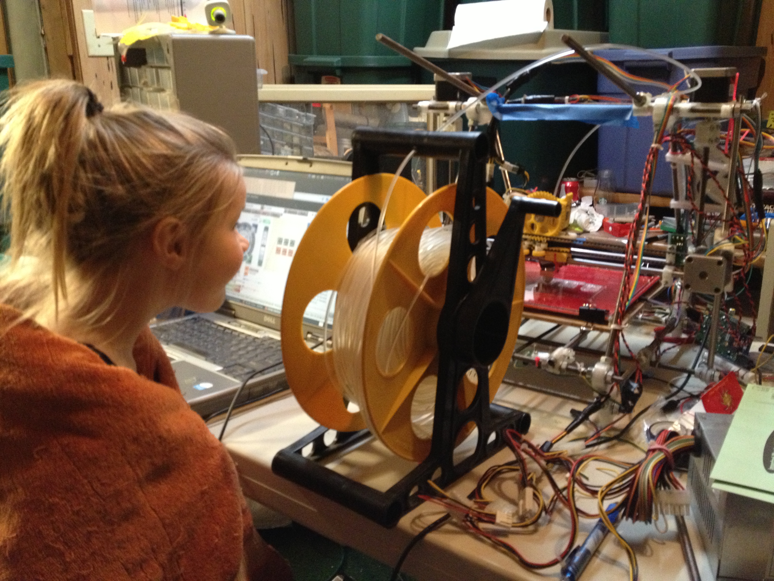
Cara was downstairs and help me attach the new X-carriage to the LM8UU bearings:
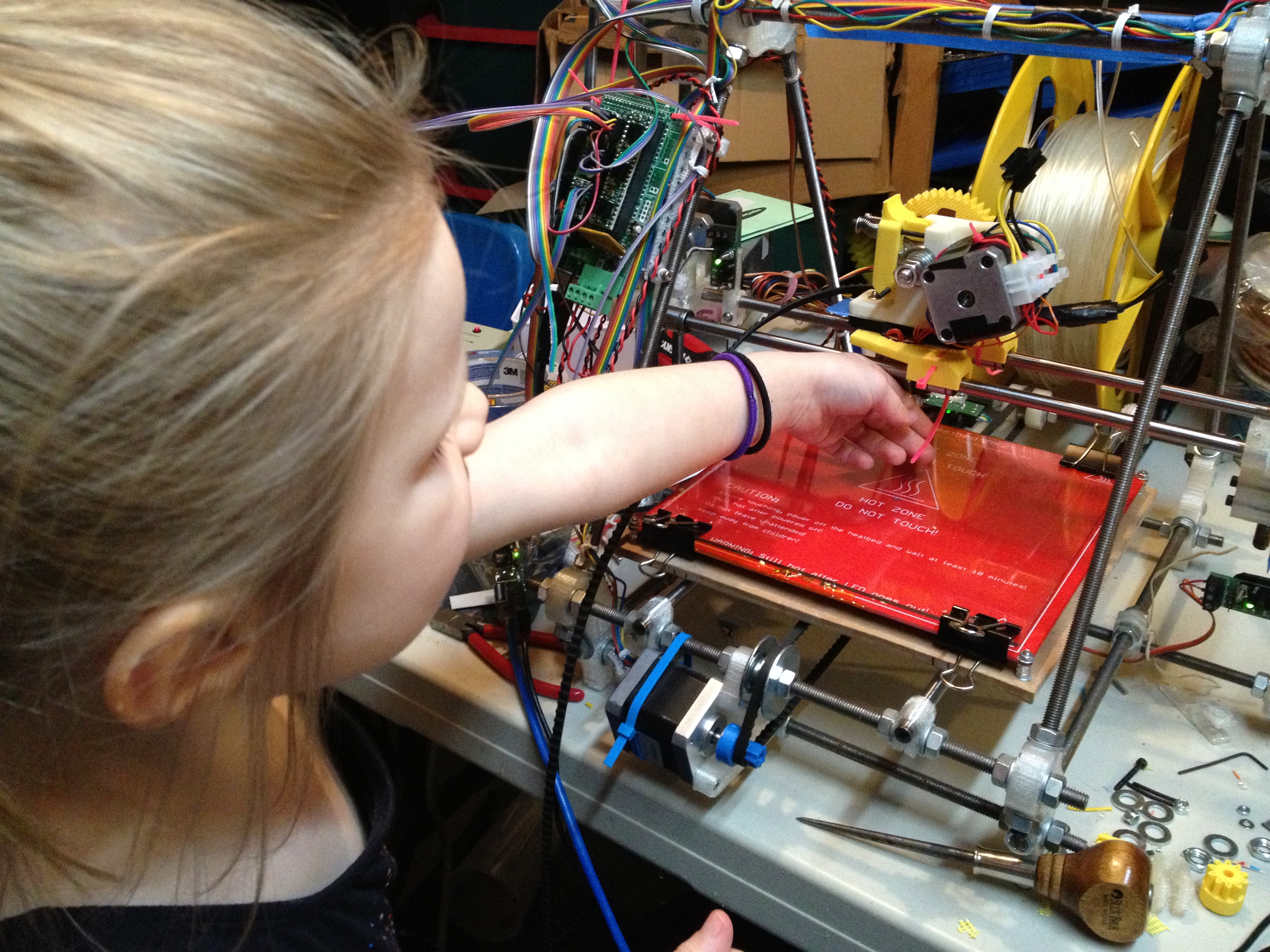
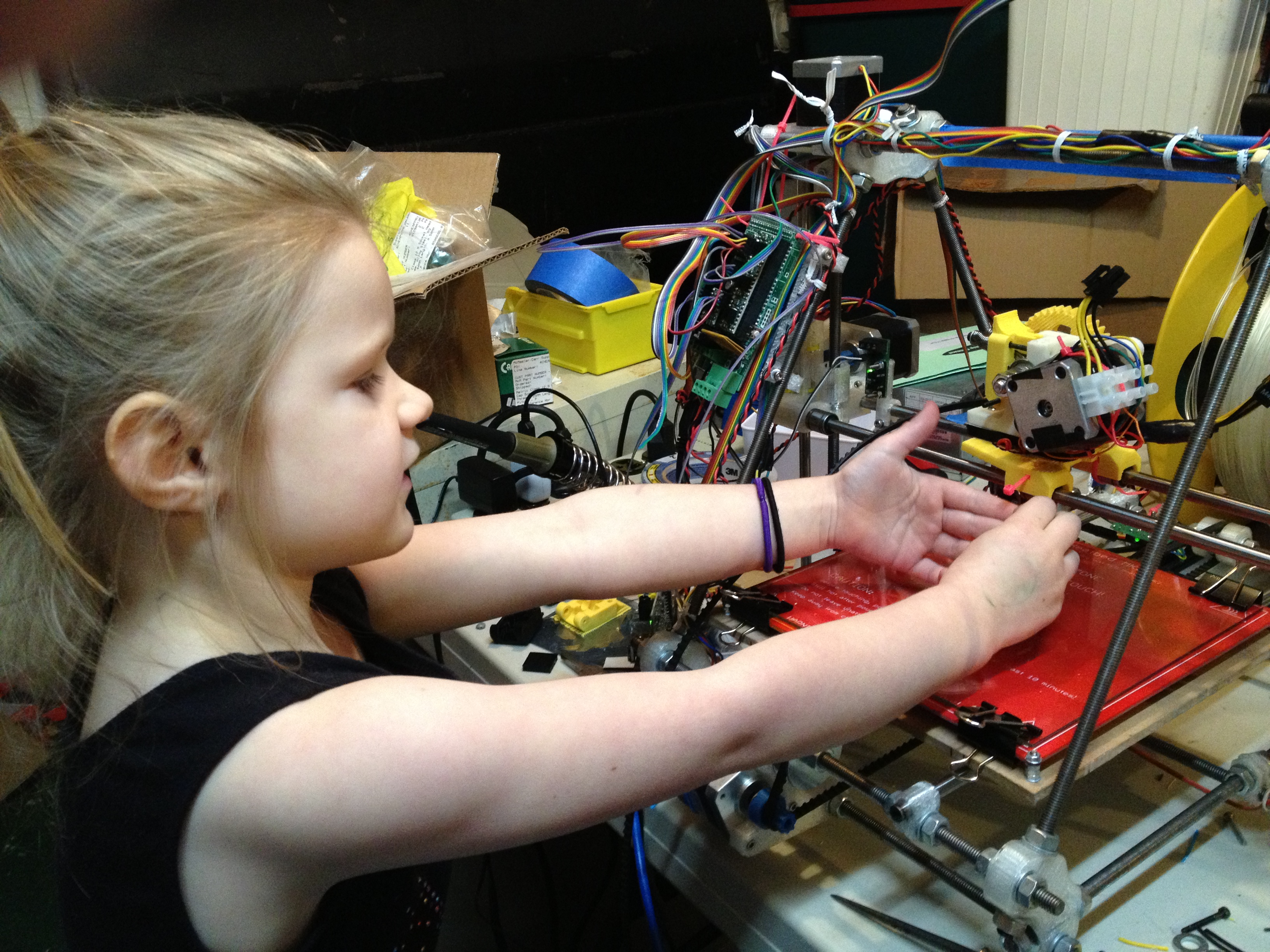
..and here she is describing it (again, a truncated video – sorry for missing her saying goodbye):
Cara is a really good RepRap helper.

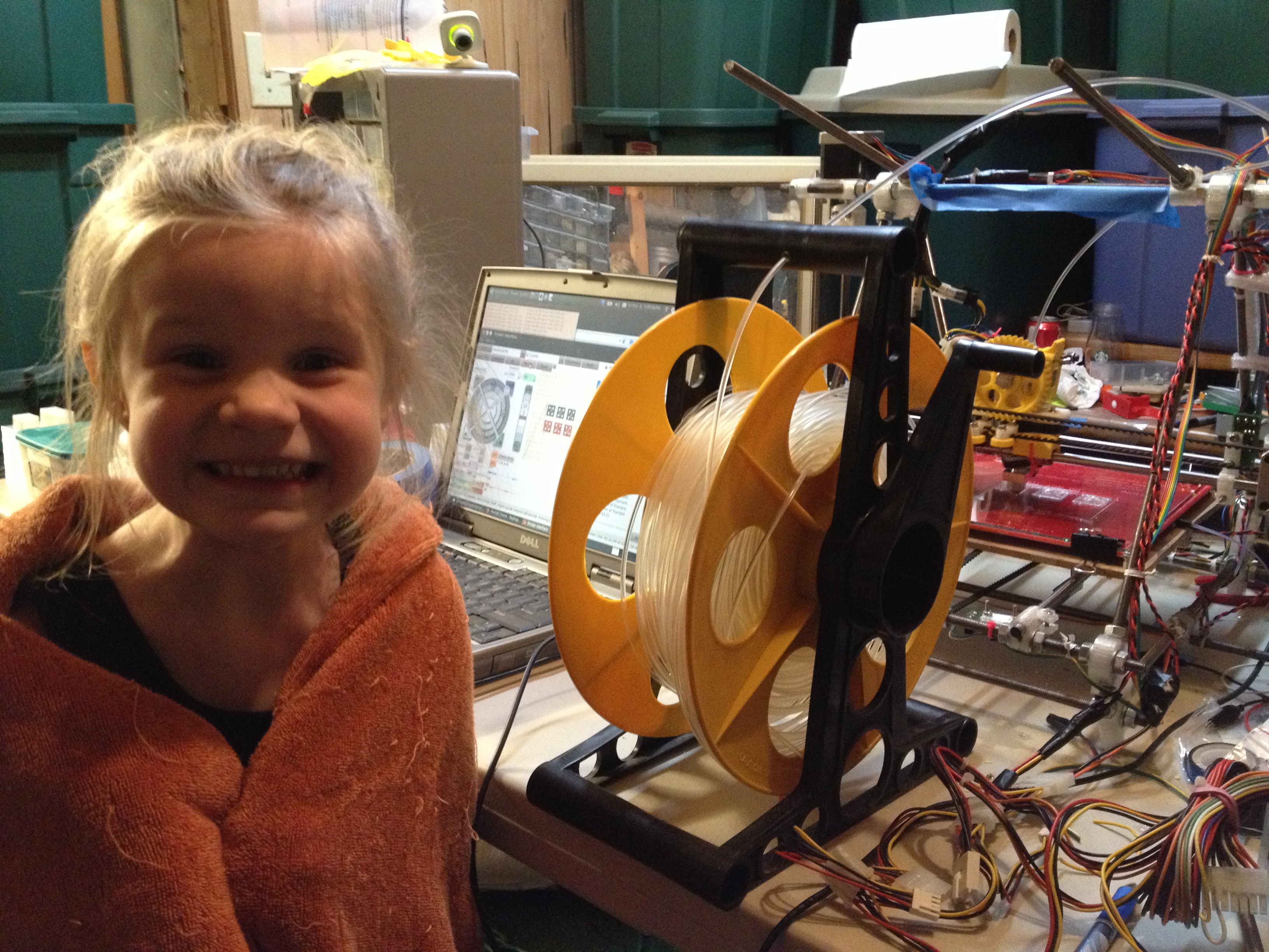
Here she is, telling us what the RepRap is doing.
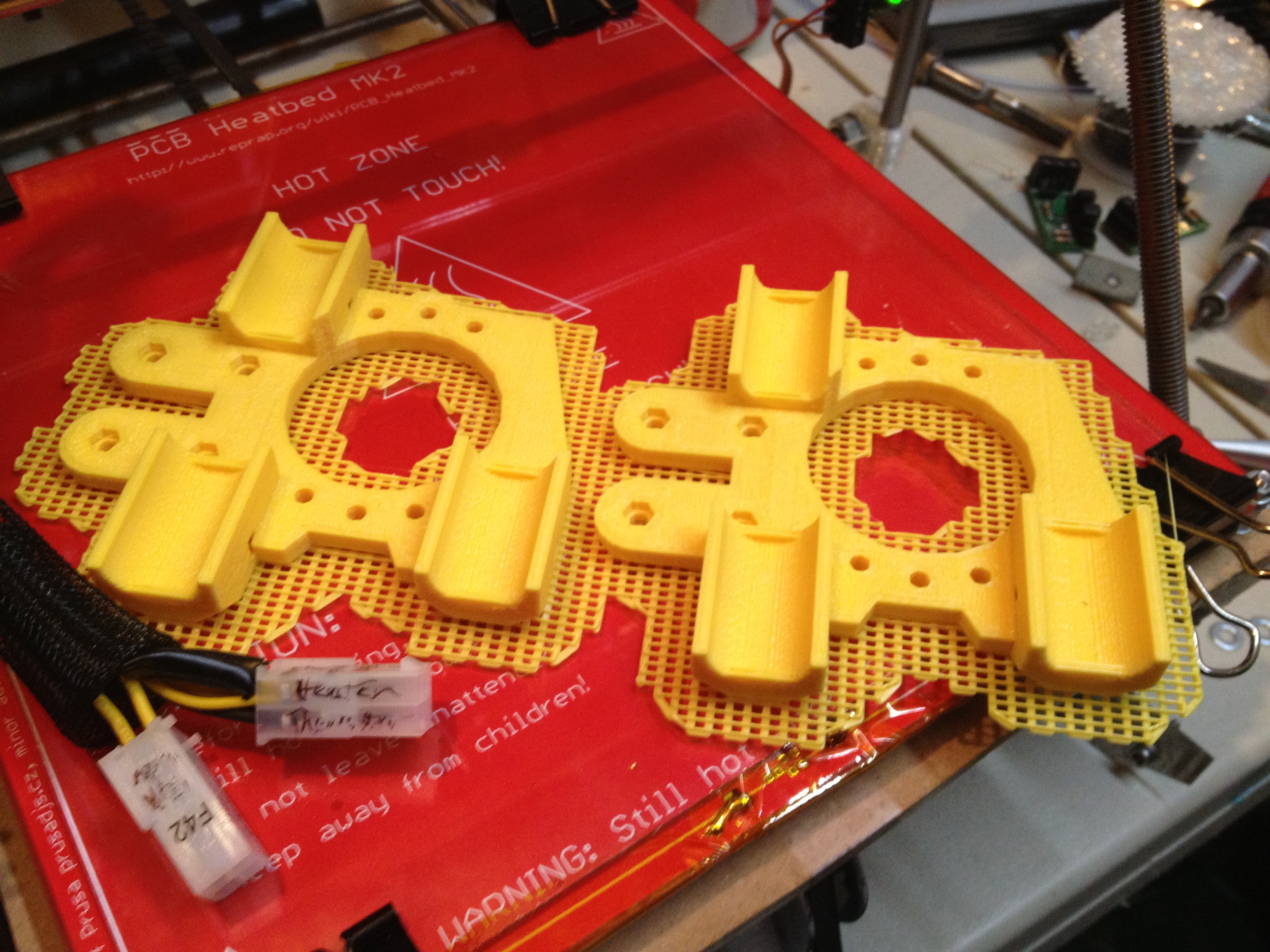
The four new-style clamps turned out great, although as I said before we only needed two of them.
Then we started two of the old-style clamps for the top (I put two long bolts through diagonal holes, pointing up, and use those as guides to hold the threaded rod that goes inside the spool).
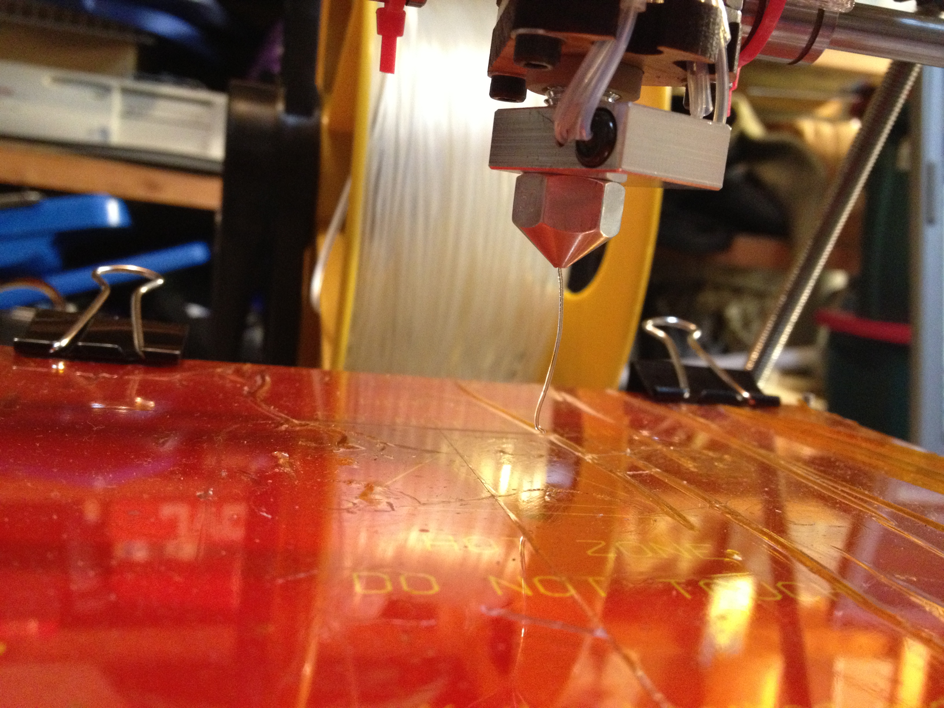
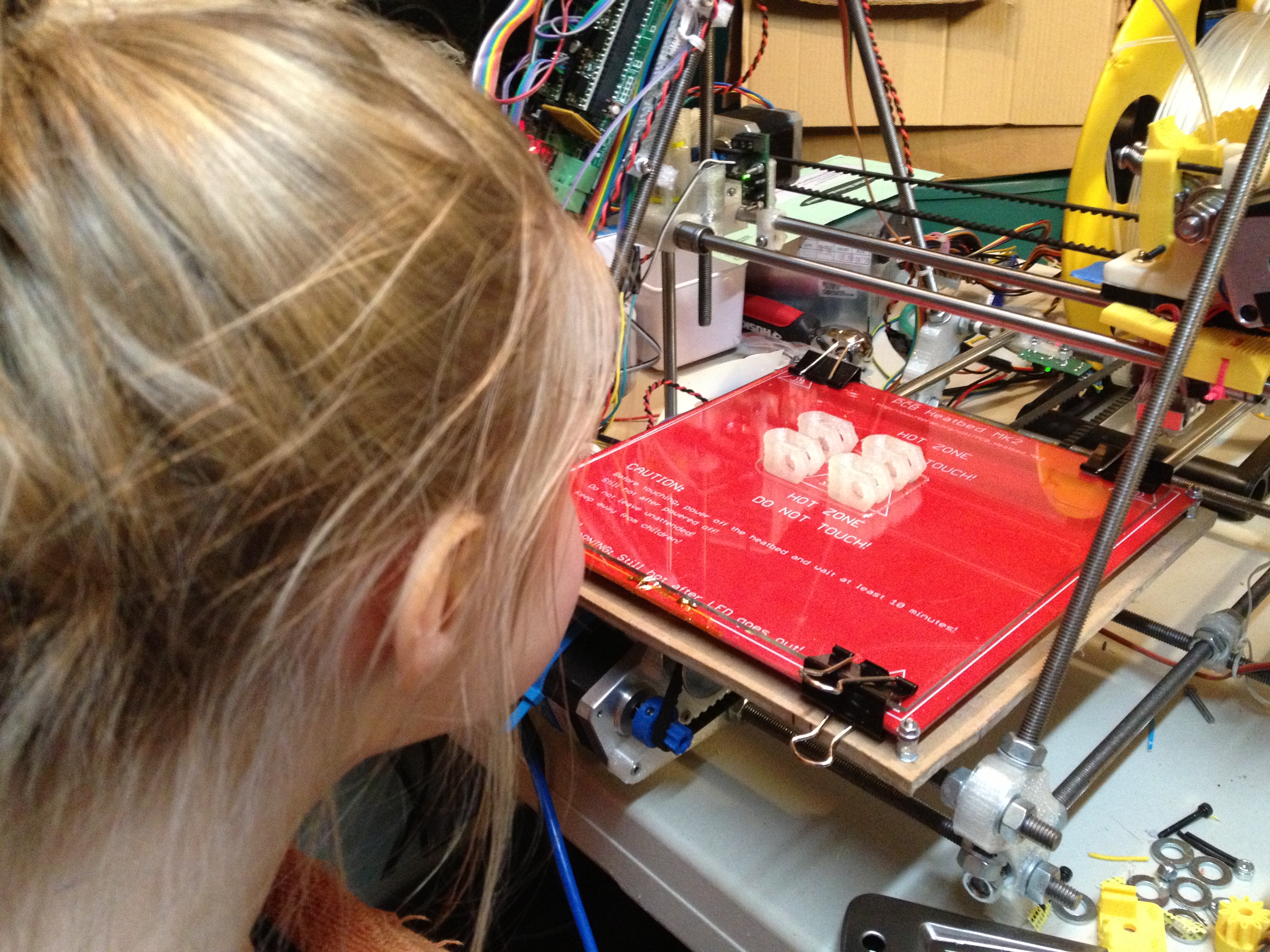
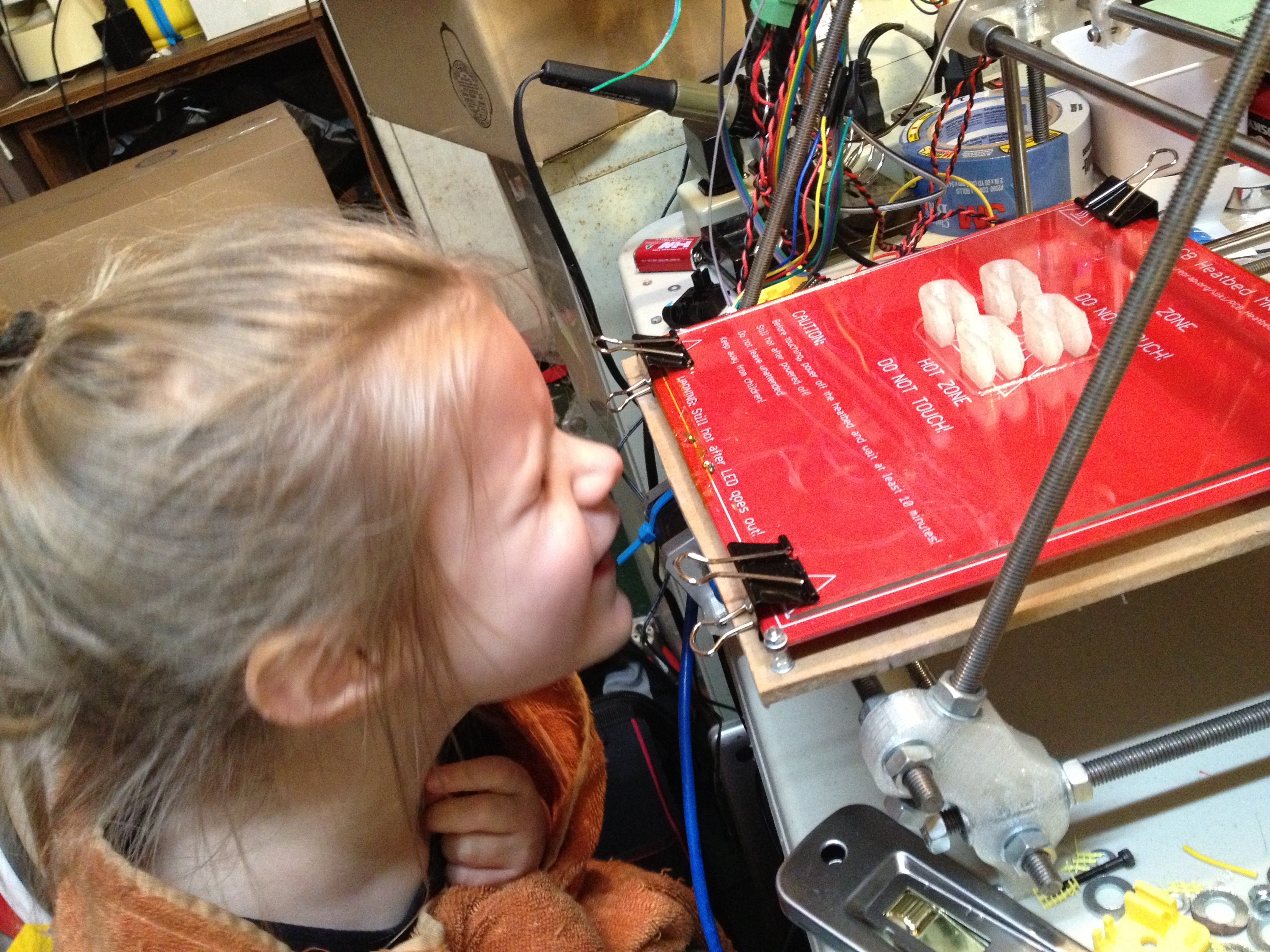
and my favorite picture of the whole post:
Well that catches us up to March 8th 2013, leaving me still just barely over a year behind. Clearly I need a combination of blogging more often and to stop using my RepRap. 🙂
See you in the next post.